

AJD610WA User Guide
Page 3
... the Camera Section . . . . . 5 ÁFeatures of the VTR Section 8 ÁSystem Configuration 9 Controls and Their Functions ÁPower Supply Section 10 ÁAccessory Mounting Section 11 ÁAudio Function Section 12 ÁShooting (Recording)/Playback Function Section 14 ÁMenu Operation Section 20 ÁTime Code-Related Section 20 ÁWarning/Status Display Section . . . . . 22 Power Supply ÁUsing an Anton Bauer Battery Pack 23 ÁUsing the Panasonic...
... the Camera Section . . . . . 5 ÁFeatures of the VTR Section 8 ÁSystem Configuration 9 Controls and Their Functions ÁPower Supply Section 10 ÁAccessory Mounting Section 11 ÁAudio Function Section 12 ÁShooting (Recording)/Playback Function Section 14 ÁMenu Operation Section 20 ÁTime Code-Related Section 20 ÁWarning/Status Display Section . . . . . 22 Power Supply ÁUsing an Anton Bauer Battery Pack 23 ÁUsing the Panasonic...

AJD610WA User Guide
Page 4
... Synchro Scan Mode . . . . . 79 ÁChanging the Shutter Speed/Mode Selection Range 80 Changing the Iris Automatic Adjustment Reference Value 80 Adjusting the Audio Level 81 Setting the Time Data ÁSetting the Time Code 83 ÁSetting the User Bit 84 ÁLocking the Time Code to an External Source 85 ÁExternal Lock Operation Procedure 85 Using the user data 86 ÁUser data operation 86 ÁSaving the user data 86 ÁLoading the user data 86 Setup Card Operations ÁSetup Card Handling 87 ÁSetup Card Data Operations...
... Synchro Scan Mode . . . . . 79 ÁChanging the Shutter Speed/Mode Selection Range 80 Changing the Iris Automatic Adjustment Reference Value 80 Adjusting the Audio Level 81 Setting the Time Data ÁSetting the Time Code 83 ÁSetting the User Bit 84 ÁLocking the Time Code to an External Source 85 ÁExternal Lock Operation Procedure 85 Using the user data 86 ÁUser data operation 86 ÁSaving the user data 86 ÁLoading the user data 86 Setup Card Operations ÁSetup Card Handling 87 ÁSetup Card Data Operations...

AJD610WA User Guide
Page 5
... unit a 3-CCD color video camera which features ITCCDs and a 520,000-pixel on-chip lens, and a DVCPRO format VTR which conform to PCMCIA standard ratings as setup cards. Features of the Camera Section The camera section of 4 MB or more is required to operate the Picture Link (Pix Link) function sold as an optional accessory. Setting menu The setting menu is also used for 8 different conditions. The setting menu is displayed...
... unit a 3-CCD color video camera which features ITCCDs and a 520,000-pixel on-chip lens, and a DVCPRO format VTR which conform to PCMCIA standard ratings as setup cards. Features of the Camera Section The camera section of 4 MB or more is required to operate the Picture Link (Pix Link) function sold as an optional accessory. Setting menu The setting menu is also used for 8 different conditions. The setting menu is displayed...
AJD610WA User Guide
Page 15
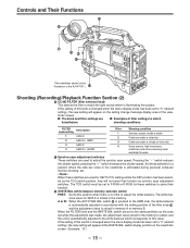
... shutter speed. A or B: When the AUTO W/B BAL switch ± is pressed to adjust the white balance. The white balance value for these switches to serve their function as the ones set to "3" (default setting), the new setting will appear at the WHITE BAL switch display position on the setting change message display area of filter settings to adjust the synchro scan speed. Controls and Their Functions ´ ®...
... shutter speed. A or B: When the AUTO W/B BAL switch ± is pressed to adjust the white balance. The white balance value for these switches to serve their function as the ones set to "3" (default setting), the new setting will appear at the WHITE BAL switch display position on the setting change message display area of filter settings to adjust the synchro scan speed. Controls and Their Functions ´ ®...

AJD610WA User Guide
Page 16
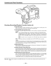
... by the camera are output. The AUTO KNEE circuit is "MANUAL KNEE". The default setting is not activated. The images shot by the camera have been selected. È OUTPUT/AUTO KNEE switch setting positions BARS CAM, AUTO KNEE OFF CAM, AUTO KNEE ON Color bar signals are output. If the setting of this switch is changed when the display mode has been set to change in the ranges preset on the setting menu. Set the switch to...
... by the camera are output. The AUTO KNEE circuit is "MANUAL KNEE". The default setting is not activated. The images shot by the camera have been selected. È OUTPUT/AUTO KNEE switch setting positions BARS CAM, AUTO KNEE OFF CAM, AUTO KNEE ON Color bar signals are output. If the setting of this switch is changed when the display mode has been set to change in the ranges preset on the setting menu. Set the switch to...
AJD610WA User Guide
Page 18
... time the button is pressed when all the super gain values have been set to STBY mode. ¹ MODE CHECK button While this 30 dB. - 18 - It does not affect the camera's output signals. º SUPER GAIN button (inside the viewfinder for details on the lens side. ¸ VTR SAVE/STBY (tape protection) switch This selects the power supply status while the VTR recording...
... time the button is pressed when all the super gain values have been set to STBY mode. ¹ MODE CHECK button While this 30 dB. - 18 - It does not affect the camera's output signals. º SUPER GAIN button (inside the viewfinder for details on the lens side. ¸ VTR SAVE/STBY (tape protection) switch This selects the power supply status while the VTR recording...
AJD610WA User Guide
Page 20
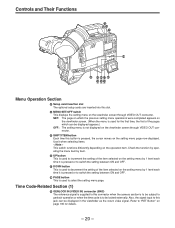
... button This is used to select the setting menu page. Time Code-Related Section (1) É GENLOCK IN/(VIDEO IN) connector (BNC) The reference signal is supplied to this button is to be locked externally. ( ) ( ) ( ) Controls and Their Functions Ã Õ Œ » Menu Operation Section à Setup card insertion slot The optional setup cards are inserted into this jack can be displayed appears.) OFF: The setting menu is not displayed on the viewfinder screen through VIDEO OUT connector. SET...
... button This is used to select the setting menu page. Time Code-Related Section (1) É GENLOCK IN/(VIDEO IN) connector (BNC) The reference signal is supplied to this button is to be locked externally. ( ) ( ) ( ) Controls and Their Functions Ã Õ Œ » Menu Operation Section à Setup card insertion slot The optional setup cards are inserted into this jack can be displayed appears.) OFF: The setting menu is not displayed on the viewfinder screen through VIDEO OUT connector. SET...
AJD610WA User Guide
Page 21
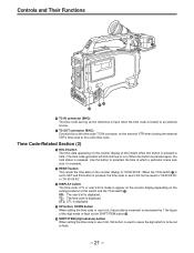
... button Ð. Ð SHIFT/ITEM (digit advance) button When setting the time code or user's bit, this button is used to cause the digit which a particular scene was shot, for example. Í RESET button This resets the time data on the setting positions of the digit made to this unit's time code. TC: The time code is displayed. When the TCG switch Ñ is set to SET and this button is pressed, the time code or user's bit can be set...
... button Ð. Ð SHIFT/ITEM (digit advance) button When setting the time code or user's bit, this button is used to cause the digit which a particular scene was shot, for example. Í RESET button This resets the time data on the setting positions of the digit made to this unit's time code. TC: The time code is displayed. When the TCG switch Ñ is set to SET and this button is pressed, the time code or user's bit can be set...
AJD610WA User Guide
Page 22
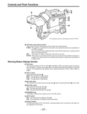
... used for setting the time code or user's bit. ON: The back tally lamp operates. The brightness when lighted can be advanced continuously regardless of the VTR's operation. The time code will be advanced only while recording is to warn the operator. HIGH: The tally lamp is set the running mode of unedited shots. Set to the VTR section, remaining battery level, sound level, time data, etc. Warning/Status Display...
... used for setting the time code or user's bit. ON: The back tally lamp operates. The brightness when lighted can be advanced continuously regardless of the VTR's operation. The time code will be advanced only while recording is to warn the operator. HIGH: The tally lamp is set the running mode of unedited shots. Set to the VTR section, remaining battery level, sound level, time data, etc. Warning/Status Display...

AJD610WA User Guide
Page 46
... camera section functions to be set to OFF before the 6-pin cable is connected or disconnected. ÁWhen OFF has been set for ECU DATA SAVE on the SUB menu CAMERA SW MODE page of MAIN menu screen 2 of 4 ÁAll adjustments and settings made .) ÁNote that the AQ-EC1 gain switch displays p3, 0 and 9 correspond to L, M and H, and the OUTPUT switch settings CAMERA, TEST and BAR to CAM/AUTO...
... camera section functions to be set to OFF before the 6-pin cable is connected or disconnected. ÁWhen OFF has been set for ECU DATA SAVE on the SUB menu CAMERA SW MODE page of MAIN menu screen 2 of 4 ÁAll adjustments and settings made .) ÁNote that the AQ-EC1 gain switch displays p3, 0 and 9 correspond to L, M and H, and the OUTPUT switch settings CAMERA, TEST and BAR to CAM/AUTO...
AJD610WA User Guide
Page 52
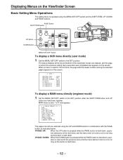
... REAR AUDIO IN MIC MIC LINE DOWN MENU SET OFF CUE CH 1 MIX CH 2 CH 1 CH 2 REAR MIC POWER ON OFF MENU SET/OFF Switch To display a SUB menu directly (user mode) 1 Set the MENU SET/OFF switch to the SET position while the SHIFT/ITEM button and UP button are cleared, and the page on which the previous setting menu operation was completed now appears on the screen. Displaying Menus on the Viewfinder Screen Basic Setting Menu Operations The setting menu is operated using...
... REAR AUDIO IN MIC MIC LINE DOWN MENU SET OFF CUE CH 1 MIX CH 2 CH 1 CH 2 REAR MIC POWER ON OFF MENU SET/OFF Switch To display a SUB menu directly (user mode) 1 Set the MENU SET/OFF switch to the SET position while the SHIFT/ITEM button and UP button are cleared, and the page on which the previous setting menu operation was completed now appears on the screen. Displaying Menus on the Viewfinder Screen Basic Setting Menu Operations The setting menu is operated using...
AJD610WA User Guide
Page 63
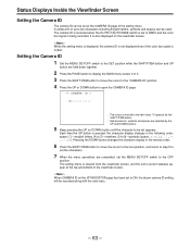
... unit's current statuses appear at the CAMERA ID page of the setting menu. The camera ID is recorded when the OUTPUT/AUTO KNEE switch is set the characters. 7 When the menu operations are selected by the UP and DOWN buttons. 5 Keep pressing the UP (or DOWN) button until the character to ON, the above camera ID setting will be recorded along with the color bars. - 63 - Each time...
... unit's current statuses appear at the CAMERA ID page of the setting menu. The camera ID is recorded when the OUTPUT/AUTO KNEE switch is set the characters. 7 When the menu operations are selected by the UP and DOWN buttons. 5 Keep pressing the UP (or DOWN) button until the character to ON, the above camera ID setting will be recorded along with the color bars. - 63 - Each time...

AJD610WA User Guide
Page 73
... conditions are not linked to PRST. If flickering is no Time to Adjust the White Balance Set the WHITE BAL switch to the filter. If the error message continues to ON and stabilize the shooting conditions. When there is a problem, turn the SHUTTER switch to appear even after...The white balance memories fall into two categories, A and B. The unit contains 4 filters, making a total of the memories are unstable (shooting is taking place under fluorescent lighting or the camera is displayed on the "CAMERA SW MODE" SUB menu page of MAIN menu screen 2 of the FILTER knob (outside).
... conditions are not linked to PRST. If flickering is no Time to Adjust the White Balance Set the WHITE BAL switch to the filter. If the error message continues to ON and stabilize the shooting conditions. When there is a problem, turn the SHUTTER switch to appear even after...The white balance memories fall into two categories, A and B. The unit contains 4 filters, making a total of the memories are unstable (shooting is taking place under fluorescent lighting or the camera is displayed on the "CAMERA SW MODE" SUB menu page of MAIN menu screen 2 of the FILTER knob (outside).
AJD610WA User Guide
Page 91
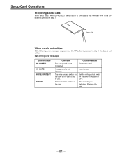
Setup Card Operations Protecting stored data If the setup card's WRITE PROTECT switch is set to ON. Data writing error messages Error message NO CONFIG NO CARD WRITE PROTECT ERROR Condition The setup card is pressed in step 7, the data is not inserted. Countermeasure Format the card. Replace the card. - 91 - Data cannot be defective. The card may be written on the card. Set to ON. A setup card is not written. The write protect switch on the...
Setup Card Operations Protecting stored data If the setup card's WRITE PROTECT switch is set to ON. Data writing error messages Error message NO CONFIG NO CARD WRITE PROTECT ERROR Condition The setup card is pressed in step 7, the data is not inserted. Countermeasure Format the card. Replace the card. - 91 - Data cannot be defective. The card may be written on the card. Set to ON. A setup card is not written. The write protect switch on the...
AJD610WA User Guide
Page 118
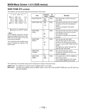
... the skin tone from among the colors set to be seen. The underlining in the variable range column indicates the setting in the preset mode. ENG 2...5 50 1 . . . This changes the coring in the phase direction. MAIN Menu Screen 1 of 4 (SUB menus) SKIN TONE DTL screen The camera's skin tone detail settings are performed on this screen. ¢| S K I N T ON E D T L { »S K I N SK I N SK I N SK...
... the skin tone from among the colors set to be seen. The underlining in the variable range column indicates the setting in the preset mode. ENG 2...5 50 1 . . . This changes the coring in the phase direction. MAIN Menu Screen 1 of 4 (SUB menus) SKIN TONE DTL screen The camera's skin tone detail settings are performed on this screen. ¢| S K I N T ON E D T L { »S K I N SK I N SK I N SK...
AJD610WA User Guide
Page 120
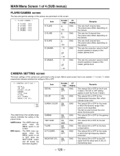
... button are performed on this screen. This selects ON or OFF for the 2-dimensional low-pass filter, which the dynamic range of the color is set to boost the color above the knee point. This selects ON or OFF for the flare compensation. The preset value differs depending on the camera. USER menu: The USER menu appears when the MENU switch...
... button are performed on this screen. This selects ON or OFF for the 2-dimensional low-pass filter, which the dynamic range of the color is set to boost the color above the knee point. This selects ON or OFF for the flare compensation. The preset value differs depending on the camera. USER menu: The USER menu appears when the MENU switch...
AJD610WA User Guide
Page 123
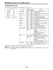
.../A/B display. USER menu: The USER menu appears when the MENU switch is set to be displayed inside the viewfinder is set to SET while the SHIFT/ITEM button and UP button are held down together. - 123 - MAIN Menu Screen 2 of 4 (SUB menus) VF INDICATOR screen What information is to SET. ENG menu: The ENG menu appears when the MENU switch is displayed. The underlining in the variable range column indicates the setting in the preset mode...
.../A/B display. USER menu: The USER menu appears when the MENU switch is set to be displayed inside the viewfinder is set to SET while the SHIFT/ITEM button and UP button are held down together. - 123 - MAIN Menu Screen 2 of 4 (SUB menus) VF INDICATOR screen What information is to SET. ENG menu: The ENG menu appears when the MENU switch is displayed. The underlining in the variable range column indicates the setting in the preset mode...

AJD610WA User Guide
Page 128
...: The UBG value is slave-locked when an external TC signal has been input. (The user setting is used when there is no 26P control). BOTH: Unit and 26P remote control (tally LED displays unit's REC status). TIME: For hour/minute/second realtime operations. OFF: All operations are set on this screen. ¢| V T R F U N C T I ON { HUM I D OPE : OFF 2 6 P CONTROL : OF F REC START : NORMA L T C MODE : DF UB MODE : USER PAUSE T I MER : 3 0 BATTERY SEL : N i Cd 1 2 TCG VF...
...: The UBG value is slave-locked when an external TC signal has been input. (The user setting is used when there is no 26P control). BOTH: Unit and 26P remote control (tally LED displays unit's REC status). TIME: For hour/minute/second realtime operations. OFF: All operations are set on this screen. ¢| V T R F U N C T I ON { HUM I D OPE : OFF 2 6 P CONTROL : OF F REC START : NORMA L T C MODE : DF UB MODE : USER PAUSE T I MER : 3 0 BATTERY SEL : N i Cd 1 2 TCG VF...
AJD610WA User Guide
Page 146
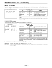
... the power ON Rotating time of the drum Number of 4 (SUB menus) INITIALIZE screen The MENU display item settings are reset on this screen. | D I AGNOST I C { OPERAT I ON : 0 0 0 0 0 ∑1 0 h DRUM RUNN I NG : 0 0 0 0 0 ∑1 0 h THREAD I T E US ER DA T A Item READ FACTORY DATA WRITE USER DATA Variable range -- -- ENG menu: The ENG menu appears when the MENU switch is set to the factory settings. VF display ENG ENG ENG ENG ENG ENG ENG Remarks Unit's operating time with...
... the power ON Rotating time of the drum Number of 4 (SUB menus) INITIALIZE screen The MENU display item settings are reset on this screen. | D I AGNOST I C { OPERAT I ON : 0 0 0 0 0 ∑1 0 h DRUM RUNN I NG : 0 0 0 0 0 ∑1 0 h THREAD I T E US ER DA T A Item READ FACTORY DATA WRITE USER DATA Variable range -- -- ENG menu: The ENG menu appears when the MENU switch is set to the factory settings. VF display ENG ENG ENG ENG ENG ENG ENG Remarks Unit's operating time with...

AJD610WA User Guide
Page 154
... CH2 changes in accordance with the sound level. (3) Inspection of the tape running status. 7 Set the DISPLAY switch to UB. Check that the speaker volume changes. 3 Connect an earphone to R-RUN. 4 Press the VTR START button. Check that the counter display number changes regardless of Audio Level Manual Adjustment Functions 1 Set the AUDIO IN CH1/CH2 switch to FRONT [MIC]. 2 Set the AUDIO SELECT CH1/CH2 switch to MAN. 3 Turn the AUDIO LEVEL CH1/CH2 controls and...
... CH2 changes in accordance with the sound level. (3) Inspection of the tape running status. 7 Set the DISPLAY switch to UB. Check that the speaker volume changes. 3 Connect an earphone to R-RUN. 4 Press the VTR START button. Check that the counter display number changes regardless of Audio Level Manual Adjustment Functions 1 Set the AUDIO IN CH1/CH2 switch to FRONT [MIC]. 2 Set the AUDIO SELECT CH1/CH2 switch to MAN. 3 Turn the AUDIO LEVEL CH1/CH2 controls and...


