
AJD850 User Guide
Page 2
... programs, video tapes and other materials may infringe the right of time, protect it from dirt and dust. To assure continued compliance follow the attached installation instructions and do not place anything on the unit. s Avoid operating or leaving the unit near strong magnetic fields. s If the unit is not going to be used only for either Color or Black & White recording...
... programs, video tapes and other materials may infringe the right of time, protect it from dirt and dust. To assure continued compliance follow the attached installation instructions and do not place anything on the unit. s Avoid operating or leaving the unit near strong magnetic fields. s If the unit is not going to be used only for either Color or Black & White recording...
AJD850 User Guide
Page 3
...; Menu menu 77 Time code/user bit 78 • Recording internal/external time codes 79 • Reproducing the time code/user bit 80 Superimpose screen 81 Servo reference 82 Audio V Fade Function 84 Printed circuit board 85 Rack mounting 86 Video head cleaning 87 Condensation 87 Error messages 88 Table of AUTO OFF Error messages 90 RS-232C interface 92 Connector signals 99 Specifications 101 Before operating this unit, check that all of its accessories...
...; Menu menu 77 Time code/user bit 78 • Recording internal/external time codes 79 • Reproducing the time code/user bit 80 Superimpose screen 81 Servo reference 82 Audio V Fade Function 84 Printed circuit board 85 Rack mounting 86 Video head cleaning 87 Condensation 87 Error messages 88 Table of AUTO OFF Error messages 90 RS-232C interface 92 Connector signals 99 Specifications 101 Before operating this unit, check that all of its accessories...
AJD850 User Guide
Page 4
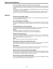
... speed is a 4U size digital VTR. Digital audio output in slow-motion/jog mode This enables smooth playback of up to search for the unit's setup can be carried around or mounted in picture quality and sound quality resulting from the external controller or other such device: -0.43/-0.3/-0.2/ -0.1/-0.03/0/+0.03/+0.1/+0.2/+0.3/+0.5/+0.75. Audio memory unit (AJ-YA752) supported Voice-over "). Features Compact size and light weight This is changed. The width of...
... speed is a 4U size digital VTR. Digital audio output in slow-motion/jog mode This enables smooth playback of up to search for the unit's setup can be carried around or mounted in picture quality and sound quality resulting from the external controller or other such device: -0.43/-0.3/-0.2/ -0.1/-0.03/0/+0.03/+0.1/+0.2/+0.3/+0.5/+0.75. Audio memory unit (AJ-YA752) supported Voice-over "). Features Compact size and light weight This is changed. The width of...
AJD850 User Guide
Page 5
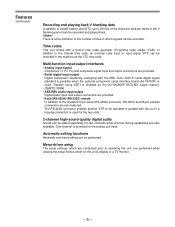
... input/output Component (Y, PB, PR) and composite signal input and output connectors are performed while viewing the setup menus either on the unit's display or a TV monitor. - 5 - The RS-422A connector enables another VTR to be operated in which are conducted prior to the standard 9-pin serial (RS-422A) connector, RS-232C and 25-pin parallel connectors are also available. One channel is used for the two units. 2-channel high-sound-quality digital audio Sound can...
... input/output Component (Y, PB, PR) and composite signal input and output connectors are performed while viewing the setup menus either on the unit's display or a TV monitor. - 5 - The RS-422A connector enables another VTR to be operated in which are conducted prior to the standard 9-pin serial (RS-422A) connector, RS-232C and 25-pin parallel connectors are also available. One channel is used for the two units. 2-channel high-sound-quality digital audio Sound can...
AJD850 User Guide
Page 6
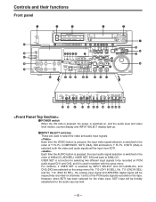
.... Each time the AUDIO button is pressed, the input audio signal selection is a function for the audio input as well. - 6 - CH2 CUE UB EXT EE LOCAL STAND BY PLAYER RECORDER RESET !6 !7 !4 #5 TC EDIT SERVO PLAY !5 REC INHIBIT REC PREVIEW REVIEW AUTO EDIT PREROLL A IN A - CF NIZE TC REC MENU SET DIAG INHIBIT 8F/4F ON REGEN REC RUN ON MANUAL MANUAL MANUAL MANUAL 2F OFF PRESET FREE RUN OFF $9 %0 %1 %2 %3 %4 %5 %6 %7 %8 %9 ^0 q POWER switch When...
.... Each time the AUDIO button is pressed, the input audio signal selection is a function for the audio input as well. - 6 - CH2 CUE UB EXT EE LOCAL STAND BY PLAYER RECORDER RESET !6 !7 !4 #5 TC EDIT SERVO PLAY !5 REC INHIBIT REC PREVIEW REVIEW AUTO EDIT PREROLL A IN A - CF NIZE TC REC MENU SET DIAG INHIBIT 8F/4F ON REGEN REC RUN ON MANUAL MANUAL MANUAL MANUAL 2F OFF PRESET FREE RUN OFF $9 %0 %1 %2 %3 %4 %5 %6 %7 %8 %9 ^0 q POWER switch When...
AJD850 User Guide
Page 7
... lamp lights. y Channel condition lamps One of these lamps lights in the deck's operation. - 7 - u AUTO OFF lamp This lights when trouble has arisen in accordance with adaptor are both acceptable. e INPUT SELECT display The characters corresponding to alert the user. t EJECT button When this slot. When the counter display indicates "CTL", the display is received. Red: The playback picture will light up . ANALOG: Analog audio signal AES/EBU: Digital audio signal USER SET: Selection...
... lamp lights. y Channel condition lamps One of these lamps lights in the deck's operation. - 7 - u AUTO OFF lamp This lights when trouble has arisen in accordance with adaptor are both acceptable. e INPUT SELECT display The characters corresponding to alert the user. t EJECT button When this slot. When the counter display indicates "CTL", the display is received. Red: The playback picture will light up . ANALOG: Analog audio signal AES/EBU: Digital audio signal USER SET: Selection...
AJD850 User Guide
Page 8
... servo and capstan servo have locked. !5 REC INHIBIT lamp This lights when the REC INHIBIT switch in order to the same speed. - 8 - manual editing commences when it is pressed together with the REC button; o REC button Recording commences when this button is pressed during playback, search, fast forward or rewind, the input signals of time, the unit automatically switches to rotate even in the...
... servo and capstan servo have locked. !5 REC INHIBIT lamp This lights when the REC INHIBIT switch in order to the same speed. - 8 - manual editing commences when it is pressed together with the REC button; o REC button Recording commences when this button is pressed during playback, search, fast forward or rewind, the input signals of time, the unit automatically switches to rotate even in the...
AJD850 User Guide
Page 9
... or UB appears on the counter display when the TC/CTL switch has been set at the setup menu No. 505 (EXT TC SEL). @1 TAPE/EE switch TAPE: For outputting the signals played back from the time code input connector or the video signal VITC. EXT: For using the unit as the recorder and a VTR equipped with an RS-422A serial interface remote control connector (9 pins). When a button other than a predetermined period, the standby...
... or UB appears on the counter display when the TC/CTL switch has been set at the setup menu No. 505 (EXT TC SEL). @1 TAPE/EE switch TAPE: For outputting the signals played back from the time code input connector or the video signal VITC. EXT: For using the unit as the recorder and a VTR equipped with an RS-422A serial interface remote control connector (9 pins). When a button other than a predetermined period, the standby...
AJD850 User Guide
Page 10
... when controlling the unit using the REMOTE connector, RS-232C connector or parallel connector. LOCAL: Set to this position when controlling the unit by the search dial. @5 JOG/SHTL/SLOW lamps These indicate the present status of the search dial and SHTL/SLOW switch. When the power has been turned on its own operation panel. @3 REMOTE lamp This lights when the REMOTE/LOCAL switch has been set to the REMOTE position. @4 Search button This button...
... when controlling the unit using the REMOTE connector, RS-232C connector or parallel connector. LOCAL: Set to this position when controlling the unit by the search dial. @5 JOG/SHTL/SLOW lamps These indicate the present status of the search dial and SHTL/SLOW switch. When the power has been turned on its own operation panel. @3 REMOTE lamp This lights when the REMOTE/LOCAL switch has been set to the REMOTE position. @4 Search button This button...
AJD850 User Guide
Page 12
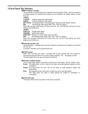
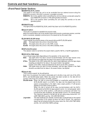
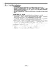
... output signal levels. Change the digit now flashing on stereo headphones when they have been pushed down. $5 Headphones jack The sound being recorded, played back or edited can be confirmed. ADJ: This is used to change the numeral of the external sync signal is within a specific range. $2 CF lamp This lights when the color framing is locked. $3 Level meters These indicate the PCM audio signal CH1/CH2, CUE track signal and video signal...
... output signal levels. Change the digit now flashing on stereo headphones when they have been pushed down. $5 Headphones jack The sound being recorded, played back or edited can be confirmed. ADJ: This is used to change the numeral of the external sync signal is within a specific range. $2 CF lamp This lights when the color framing is locked. $3 Level meters These indicate the PCM audio signal CH1/CH2, CUE track signal and video signal...
AJD850 User Guide
Page 13
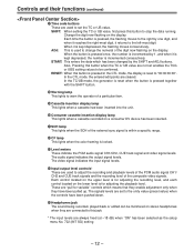
... is used to select the audio signals output to the monitor L/R channels. FULL mode: Standard scale units (ranging from -∞ to 0 dB) are used to select the scale unit display mode for the audio level meters. Each time the "R" button is set to the unity value (preset value). $7 MONITOR SELECT switches These are used to adjust the headphones volume and the monitor output volume. Whether the headphones output and monitor output volumes are to be linked or...
... is used to select the audio signals output to the monitor L/R channels. FULL mode: Standard scale units (ranging from -∞ to 0 dB) are used to select the scale unit display mode for the audio level meters. Each time the "R" button is set to the unity value (preset value). $7 MONITOR SELECT switches These are used to adjust the headphones volume and the monitor output volume. Whether the headphones output and monitor output volumes are to be linked or...
AJD850 User Guide
Page 14
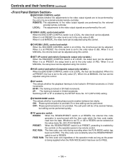
... at the setup menu No. 503 (TCG REGEN). Whether to set to REC. Switching to 8F or 4F is set to FREE. - 14 - LOCAL: The adjustments to the video output signals are performed by remote control. Error-less editing can be adjusted using this control. %1 CHROMA LEVEL control and switch When the ENCODER CONTROL switch is not provided. REC RUN: The time code runs only during recording when the RUN MODE switch has been set TC...
... at the setup menu No. 503 (TCG REGEN). Whether to set to REC. Switching to 8F or 4F is set to FREE. - 14 - LOCAL: The adjustments to the video output signals are performed by remote control. Error-less editing can be adjusted using this control. %1 CHROMA LEVEL control and switch When the ENCODER CONTROL switch is not provided. REC RUN: The time code runs only during recording when the RUN MODE switch has been set TC...
AJD850 User Guide
Page 17
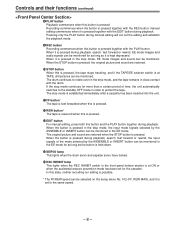
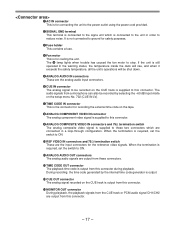
... the analog audio input connectors. e Fuse holder This contains a fuse. If the unit is still operated in a loop-through configuration. The audio signals from a microphone can also be recorded by the internal time code generator is output. !3 CUE OUT connector The analog signal recorded on the setup menu No. 702 (CUE IN LV). r Fan motor This is for recording the external time code on the CUE track is supplied to ON. !0 REF VIDEO IN connectors and...
... the analog audio input connectors. e Fuse holder This contains a fuse. If the unit is still operated in a loop-through configuration. The audio signals from a microphone can also be recorded by the internal time code generator is output. !3 CUE OUT connector The analog signal recorded on the setup menu No. 702 (CUE IN LV). r Fan motor This is for recording the external time code on the CUE track is supplied to ON. !0 REF VIDEO IN connectors and...
AJD850 User Guide
Page 26
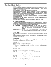
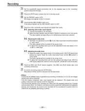
... controls and adjust them. If this lamp is lighted during recording. The REC and PLAY lamps light, and recording commences. 7 To end the recording, press the STOP button. The audio signals will be recorded. 2 Select the input signals using the INPUT SELECT switches on the TV monitor. 4 Check that the SERVO lamp is lighted, set the REC INHIBIT switch to OFF. 5 Select the video and audio input signals and adjust their levels. 5-1 Selecting video/audio input signals 1 Connect the signals...
... controls and adjust them. If this lamp is lighted during recording. The REC and PLAY lamps light, and recording commences. 7 To end the recording, press the STOP button. The audio signals will be recorded. 2 Select the input signals using the INPUT SELECT switches on the TV monitor. 4 Check that the SERVO lamp is lighted, set the REC INHIBIT switch to OFF. 5 Select the video and audio input signals and adjust their levels. 5-1 Selecting video/audio input signals 1 Connect the signals...
AJD850 User Guide
Page 34
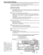
... FLASH) described on the display. 3 Search for details on the jog/shuttle operations. 2 Press the SET button while holding down the IN button. ON OFF POWER METER FULL/FINE L MONITOR SELECT R LEVEL CH1 HEADPHONES PULL OPEN INPUT SELECT VIDEO Y PB PR CMPST SDTI(V&A) SDI AUDIO ANALOG AES/EBU USER SET SDI CH2 REC CUE VIDEO PB PULL FOR VARIABLE CH CONDITION TC/CTL TC MODE CONTROL TC...
... FLASH) described on the display. 3 Search for details on the jog/shuttle operations. 2 Press the SET button while holding down the IN button. ON OFF POWER METER FULL/FINE L MONITOR SELECT R LEVEL CH1 HEADPHONES PULL OPEN INPUT SELECT VIDEO Y PB PR CMPST SDTI(V&A) SDI AUDIO ANALOG AES/EBU USER SET SDI CH2 REC CUE VIDEO PB PULL FOR VARIABLE CH CONDITION TC/CTL TC MODE CONTROL TC...
AJD850 User Guide
Page 50
... the SET button. ON OFF POWER METER FULL/FINE L MONITOR SELECT R LEVEL CH1 HEADPHONES PULL OPEN INPUT SELECT VIDEO Y PB PR CMPST SDTI(V&A) SDI AUDIO ANALOG AES/EBU USER SET SDI CH2 REC CUE VIDEO PB PULL FOR VARIABLE CH CONDITION TC/CTL TC MODE CONTROL TC INT TAPE REMOTE W ASSEMBLE TC SET SHIFT ADJ START DV SCH CF VIDEO CH1 CH2 CUE INSERT- on the display flashes...
... the SET button. ON OFF POWER METER FULL/FINE L MONITOR SELECT R LEVEL CH1 HEADPHONES PULL OPEN INPUT SELECT VIDEO Y PB PR CMPST SDTI(V&A) SDI AUDIO ANALOG AES/EBU USER SET SDI CH2 REC CUE VIDEO PB PULL FOR VARIABLE CH CONDITION TC/CTL TC MODE CONTROL TC INT TAPE REMOTE W ASSEMBLE TC SET SHIFT ADJ START DV SCH CF VIDEO CH1 CH2 CUE INSERT- on the display flashes...
AJD850 User Guide
Page 57
...) 5: Time and recording date (month/day/year) 6: Time and recording date (day/month/year) • "DVCPRO MODE," "DV MODE" or "DVCAM MODE" is displayed as the mode when a DVCPRO, DV or DVCAM format tape is used, respectively. • When setting 2 (T&S&M) is used to select what is changed so that the characters are automatically displayed in a position on the horizontal plane for the time code and other super displays output to VIDEO...
...) 5: Time and recording date (month/day/year) 6: Time and recording date (day/month/year) • "DVCPRO MODE," "DV MODE" or "DVCAM MODE" is displayed as the mode when a DVCPRO, DV or DVCAM format tape is used, respectively. • When setting 2 (T&S&M) is used to select what is changed so that the characters are automatically displayed in a position on the horizontal plane for the time code and other super displays output to VIDEO...
AJD850 User Guide
Page 59
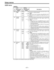
... This sets the status until the audio signal is output when operation switches from the stop or search modes to the search mode unless the search button is pressed. 101 SHTL MAX 0000 0001 0002 ×16 This sets the maximum speed for audio 106 PLAY DELAY 000... 0 0015 ... 0 This set to 0 (OFF), the sound in the STOP, FF or REW mode. USER menu Item Setting Superimposed Superimposed No. display No...
... This sets the status until the audio signal is output when operation switches from the stop or search modes to the search mode unless the search button is pressed. 101 SHTL MAX 0000 0001 0002 ×16 This sets the maximum speed for audio 106 PLAY DELAY 000... 0 0015 ... 0 This set to 0 (OFF), the sound in the STOP, FF or REW mode. USER menu Item Setting Superimposed Superimposed No. display No...
AJD850 User Guide
Page 60
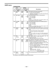
... zero point is inserted. 1. Setup menus USER menu (continued) Item Setting Superimposed Superimposed No. If a DV or DVCAM tape is inserted when the DVCPRO mode setting has been selected, the recording operation will be conducted but no guarantee is inserted when the DV or DVCAM mode setting has been selected. 2. The REMAIN display fails to problems with the preroll operation, and it automatically stops...
... zero point is inserted. 1. Setup menus USER menu (continued) Item Setting Superimposed Superimposed No. If a DV or DVCAM tape is inserted when the DVCPRO mode setting has been selected, the recording operation will be conducted but no guarantee is inserted when the DV or DVCAM mode setting has been selected. 2. The REMAIN display fails to problems with the preroll operation, and it automatically stops...
AJD850 User Guide
Page 62
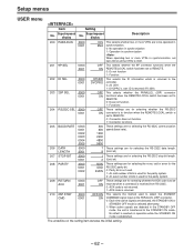
... the REMOTE/LOCAL switch has been set to REMOTE. 0: Does not function 1: Functions These settings are to be returned when a command is received from RS-232C. 0: ACK code is not returned. 1: ACK code is set item 200 of bits is used to detect the STANDBY COMMAND signal input at the PARALLEL (25P) connector. 0: Each time active signals are detected, the STANDBY ON or STANDBY OFF mode...
... the REMOTE/LOCAL switch has been set to REMOTE. 0: Does not function 1: Functions These settings are to be returned when a command is received from RS-232C. 0: ACK code is not returned. 1: ACK code is set item 200 of bits is used to detect the STANDBY COMMAND signal input at the PARALLEL (25P) connector. 0: Each time active signals are detected, the STANDBY ON or STANDBY OFF mode...


