
AJEC3 User Guide
Page 2
... displays for purchasing this AJ-EC3 Extension Control Unit (which will subsequently be referred to in these instructions as "the unit"). Thank you for VIDEO OUT output E-10 MAIN MENU 1 of 2 E-11 MAIN MENU 2 of functions for supporting DVCPRO, DVCPRO50 and DVCPRO HD camera recorders. indicates safety items. E-1 The unit features high performance and a variety of...
... displays for purchasing this AJ-EC3 Extension Control Unit (which will subsequently be referred to in these instructions as "the unit"). Thank you for VIDEO OUT output E-10 MAIN MENU 1 of 2 E-11 MAIN MENU 2 of functions for supporting DVCPRO, DVCPRO50 and DVCPRO HD camera recorders. indicates safety items. E-1 The unit features high performance and a variety of...
AJEC3 User Guide
Page 3
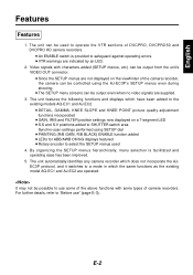
...unit automatically identifies any camera recorder which have been added to the existing models AQ-EC1 and AJ-EC2. ≥ DETAIL, GAMMA, KNEE SLOPE and KNEE POINT picture quality adjustment functions incorporated ≥ GAIN, IRIS and FILTER position settings now displayed on the viewfinder of the camera recorder, the camera can be controlled... for ABB/AWB OK/NG displays featured ≥ Rotary encoder to operate the VTR sections of camera recorders. E-2 The unit can be output from the unit's VIDEO OUT connector. ≥ Since the SETUP menus are indicated by an LED. 2. Video...
...unit automatically identifies any camera recorder which have been added to the existing models AQ-EC1 and AJ-EC2. ≥ DETAIL, GAMMA, KNEE SLOPE and KNEE POINT picture quality adjustment functions incorporated ≥ GAIN, IRIS and FILTER position settings now displayed on the viewfinder of the camera recorder, the camera can be controlled... for ABB/AWB OK/NG displays featured ≥ Rotary encoder to operate the VTR sections of camera recorders. E-2 The unit can be output from the unit's VIDEO OUT connector. ≥ Since the SETUP menus are indicated by an LED. 2. Video...
AJEC3 User Guide
Page 4
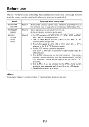
... cannot be used. 1. All the unit's other functions can be output from the camera recorder's VIDEO OUT connector. or S.V is going to be used with it. The camera recorder's menus are output from the unit. PAINTING is set to the unit's VIDEO OUT connector. 6. E-3 Model...controls cannot be used. The SETUP menus are not output to 1/60 or 1/100 when S.S. Menus are not the unit's menus. The shutter speed is enabled at all times. Before use The unit's functions may be performed. 2. Consult your dealer about this. Before use , therefore, check the camera...
... cannot be used. 1. All the unit's other functions can be output from the camera recorder's VIDEO OUT connector. or S.V is going to be used with it. The camera recorder's menus are output from the unit. PAINTING is set to the unit's VIDEO OUT connector. 6. E-3 Model...controls cannot be used. The SETUP menus are not output to 1/60 or 1/100 when S.S. Menus are not the unit's menus. The shutter speed is enabled at all times. Before use The unit's functions may be performed. 2. Consult your dealer about this. Before use , therefore, check the camera...
AJEC3 User Guide
Page 5
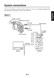
To VIDEO IN connector To VIDEO OUT connector English System connections The unit is connected to a camera recorder, monitor, etc. Mode 1 Camera recorder To VIDEO OUT connector BNC cable Cable (included) 6-pin cable To ECU connector To CAM/BS connector ECU AJECU 6 5 ∫ 1 BNC cable R B Monitor AJ-EC3P E-4 for mode 1 and modes 2/3. The examples illustrated here show the system connections for use.
To VIDEO IN connector To VIDEO OUT connector English System connections The unit is connected to a camera recorder, monitor, etc. Mode 1 Camera recorder To VIDEO OUT connector BNC cable Cable (included) 6-pin cable To ECU connector To CAM/BS connector ECU AJECU 6 5 ∫ 1 BNC cable R B Monitor AJ-EC3P E-4 for mode 1 and modes 2/3. The examples illustrated here show the system connections for use.

AJEC3 User Guide
Page 6
...on the connection of the cable (included) is going to be obtained separately if the model AJ-BS900P is not used . E-5 System connections Modes 2/3 Camera recorder BNC cable Cable (included) To VIDEO OUT connector (AJ-HDC20A: To HD HDI OUT connector) 6-pin cable To ECU connector BNC cable To ...VIDEO IN connector To CAM/BS connector ECU AJECU 6 5 ∫ 1 R B Monitor AJ-EC3P The BNC cable end of the camera recorder, monitor or other units, refer to their respective Operating Instructions. ≥ An RCOP cable must be used in mode 2 or 3.
...on the connection of the cable (included) is going to be obtained separately if the model AJ-BS900P is not used . E-5 System connections Modes 2/3 Camera recorder BNC cable Cable (included) To VIDEO OUT connector (AJ-HDC20A: To HD HDI OUT connector) 6-pin cable To ECU connector BNC cable To ...VIDEO IN connector To CAM/BS connector ECU AJECU 6 5 ∫ 1 R B Monitor AJ-EC3P The BNC cable end of the camera recorder, monitor or other units, refer to their respective Operating Instructions. ≥ An RCOP cable must be used in mode 2 or 3.

AJEC3 User Guide
Page 7
... of the AJ-EC3P. 2 START/STOP button When this to view the playback images on the camera recorder's viewfinder or on the unit. ON : The operations performed by the unit are enabled. The time code is pressed again, it stops 1 recording. Its LED remains lighted ...STOP button Press this to rewind the tape. English Parts and their functions Control panel 43 2 76 8 9 < = @ A E F I J K L ENABLE V ON T R OFF WARNING REW 6 STOP ∫ ECU AJ- This button works in exactly the same 5 way as the camera recorder's VTR start button. C D 5 REC CHK button It is ...
... of the AJ-EC3P. 2 START/STOP button When this to view the playback images on the camera recorder's viewfinder or on the unit. ON : The operations performed by the unit are enabled. The time code is pressed again, it stops 1 recording. Its LED remains lighted ...STOP button Press this to rewind the tape. English Parts and their functions Control panel 43 2 76 8 9 < = @ A E F I J K L ENABLE V ON T R OFF WARNING REW 6 STOP ∫ ECU AJ- This button works in exactly the same 5 way as the camera recorder's VTR start button. C D 5 REC CHK button It is ...

AJEC3 User Guide
Page 8
...When color bar signals are to be output from the camera area to the VTR area, viewfinder and video monitor. ∫ Setting positions of the camera recorder being used . The white balance value corresponding to the FILTER control position can also be stored in the Operating Instructions of ...CAM AUTO KNEE/BARS switch BARS : Color bar signals are output. The 3200K white balance value is stored in the memory by the camera are output. At the S.S. setting,...
...When color bar signals are to be output from the camera area to the VTR area, viewfinder and video monitor. ∫ Setting positions of the camera recorder being used . The white balance value corresponding to the FILTER control position can also be stored in the Operating Instructions of ...CAM AUTO KNEE/BARS switch BARS : Color bar signals are output. The 3200K white balance value is stored in the memory by the camera are output. At the S.S. setting,...
AJEC3 User Guide
Page 9
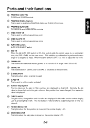
...65. English Parts and their functions B PAINTING GAIN VRs R GAIN and B GAIN controls C PAINTING ENABLE switch This is used to adjust the iris finely. This addition or subtraction is displayed. I GAMMA VR This enables the camera's master gamma to set the manual knee point. L M.PED VR This is used...filter position has been changed, the respective value is performed over a range of time has elapsed. D PAINTING BLACK VR R PEDESTAL and B PEDESTAL controls E KNEE POINT VR This is used to set the manual knee slope. K INDICATOR This lights when a lens extender is used to set the ...
...65. English Parts and their functions B PAINTING GAIN VRs R GAIN and B GAIN controls C PAINTING ENABLE switch This is used to adjust the iris finely. This addition or subtraction is displayed. I GAMMA VR This enables the camera's master gamma to set the manual knee point. L M.PED VR This is used...filter position has been changed, the respective value is performed over a range of time has elapsed. D PAINTING BLACK VR R PEDESTAL and B PEDESTAL controls E KNEE POINT VR This is used to set the manual knee slope. K INDICATOR This lights when a lens extender is used to set the ...

AJEC3 User Guide
Page 10
Parts and their functions Connector area 1 1 CAM/BS connector This is used to connect the unit with the camera recorder or AJ-BS900P. 2 VIDEO OUT connector The video signals with characters added are output 2 to this connector. E-9
Parts and their functions Connector area 1 1 CAM/BS connector This is used to connect the unit with the camera recorder or AJ-BS900P. 2 VIDEO OUT connector The video signals with characters added are output 2 to this connector. E-9

AJEC3 User Guide
Page 11
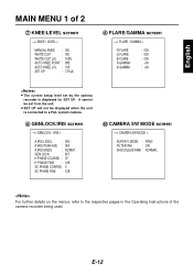
... SYNCHRO SCAN 2 VR DATA 3 MATRIX 4 DTL SETTING 5 ADDITIONAL DTL 6 SKIN TONE DTL 7 KNEE / LEVEL 8 FLARE / GAMMA 9 GENLOCK / IRIS : CAMERA SW MODE ; All the pages contained in the VIDEO OUT output. CAMERA SETTING < AUTO SHADING = DIAGNOSTIC E-10 English Menu displays for VIDEO OUT output Setting menu display for VIDEO OUT output When... setting menus are displayed in these menus and the page configuration are shown below. ≥The setting menus are not output from the unit when the AJ-HDC20A is set to the camera recorder's VIDEO OUT connector. There are displayed page by page.
... SYNCHRO SCAN 2 VR DATA 3 MATRIX 4 DTL SETTING 5 ADDITIONAL DTL 6 SKIN TONE DTL 7 KNEE / LEVEL 8 FLARE / GAMMA 9 GENLOCK / IRIS : CAMERA SW MODE ; All the pages contained in the VIDEO OUT output. CAMERA SETTING < AUTO SHADING = DIAGNOSTIC E-10 English Menu displays for VIDEO OUT output Setting menu display for VIDEO OUT output When... setting menus are displayed in these menus and the page configuration are shown below. ≥The setting menus are not output from the unit when the AJ-HDC20A is set to the camera recorder's VIDEO OUT connector. There are displayed page by page.
AJEC3 User Guide
Page 13
... A.IRIS PEAK/AVE : 050 A.IRIS MODE : NORM1 GEN LOCK : INT H PHASE COARSE : 07 H PHASE FINE : 128 SC PHASE COARSE : 0 SC PHASE FINE : 128 : CAMERA SW MODE screen < CAMERA SW MODE > SUPER V MODE : FRM1 FILTER INH : ON SHOCKLESS AWB : NORMAL For further details on the menus, refer to the respective pages in the... SET UP : 7.5%A 8 FLARE/GAMMA screen < FLARE / GAMMA > R FLARE G FLARE B FLARE R GAMMA B GAMMA : 000 : 000 : 000 : +00 : +00 ≥ The current setup level set from the unit. ≥ SET UP will not be displayed when the...
... A.IRIS PEAK/AVE : 050 A.IRIS MODE : NORM1 GEN LOCK : INT H PHASE COARSE : 07 H PHASE FINE : 128 SC PHASE COARSE : 0 SC PHASE FINE : 128 : CAMERA SW MODE screen < CAMERA SW MODE > SUPER V MODE : FRM1 FILTER INH : ON SHOCKLESS AWB : NORMAL For further details on the menus, refer to the respective pages in the... SET UP : 7.5%A 8 FLARE/GAMMA screen < FLARE / GAMMA > R FLARE G FLARE B FLARE R GAMMA B GAMMA : 000 : 000 : 000 : +00 : +00 ≥ The current setup level set from the unit. ≥ SET UP will not be displayed when the...
AJEC3 User Guide
Page 14
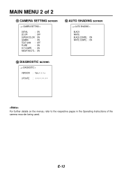
E-13 MAIN MENU 2 of the camera recorder being used. CAMERA SETTING screen < CAMERA SETTING > DETAIL : ON 2D LPF : OFF SUPER COLOR : ON GAMMA : ON TEST SAW : OFF FLARE : ON H-F COMPE. : ON NEGATIVE DTL : ON < AUTO SHADING screen < AUTO SHADING > BLACK WHITE BLACK COMPE. : ON WHITE COMPE. : ON = DIAGNOSTIC screen < DIAGNOSTIC > VERSION : Ver UP DATE For further details on the menus, refer to the respective pages in the Operating Instructions of 2 ;
E-13 MAIN MENU 2 of the camera recorder being used. CAMERA SETTING screen < CAMERA SETTING > DETAIL : ON 2D LPF : OFF SUPER COLOR : ON GAMMA : ON TEST SAW : OFF FLARE : ON H-F COMPE. : ON NEGATIVE DTL : ON < AUTO SHADING screen < AUTO SHADING > BLACK WHITE BLACK COMPE. : ON WHITE COMPE. : ON = DIAGNOSTIC screen < DIAGNOSTIC > VERSION : Ver UP DATE For further details on the menus, refer to the respective pages in the Operating Instructions of 2 ;


