
AJHD1200A User Guide
Page 2
... SHOCK HAZARD, REFER CHANGE OF SWITCH SETTING INSIDE THE UNIT TO QUALIFIED SERVICE PERSONNEL. Extension cords used with the situation by, for instance, moving the source of the magnetic fields away from the unit before operation. $ THIS APPARATUS MUST BE GROUNDED To ensure safe operation the three-pin plug must be threecore and be inserted only into a standard three-pin power outlet which generates...
... SHOCK HAZARD, REFER CHANGE OF SWITCH SETTING INSIDE THE UNIT TO QUALIFIED SERVICE PERSONNEL. Extension cords used with the situation by, for instance, moving the source of the magnetic fields away from the unit before operation. $ THIS APPARATUS MUST BE GROUNDED To ensure safe operation the three-pin plug must be threecore and be inserted only into a standard three-pin power outlet which generates...
AJHD1200A User Guide
Page 5
... switching the setting on the setup menu, the unit can be converted into 1080/24 PsF format output signals to DVCPRO HD-LP playback, the unit can perform the unit's settings interactively with a variable frame rate camera. You can play back consumer DV tapes (SP) and DVCAM tapes. 2 The unit's recording function become operational only when the AJ-YA120AG (optional accessory) or AJ-YAD120AG (optional accessory) has been installed...
... switching the setting on the setup menu, the unit can be converted into 1080/24 PsF format output signals to DVCPRO HD-LP playback, the unit can perform the unit's settings interactively with a variable frame rate camera. You can play back consumer DV tapes (SP) and DVCAM tapes. 2 The unit's recording function become operational only when the AJ-YA120AG (optional accessory) or AJ-YAD120AG (optional accessory) has been installed...
AJHD1200A User Guide
Page 6
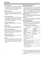
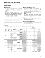
... -screen. Playback format Output format DVCPRO HD-LP, DVCPRO HD DVCPRO HD, DVCPRO50, DV DVCPRO50 DVCPRO50, DV DVCPRO DVCPRO, DV DVCPRO P, DV, DVCAM DV When the E-E mode is DVCPRO HD, established: DVCPRO50, DV O Install the AJ-YA120AG board which complies with the IEEE 1394 standard. When any of the settings below is possible. [Multi-functional interfaces] Serial digital input/output2 The unit's HD component serial I/O interface enables interfacing with HD component video signals and 8-channel digital audio signals using an...
... -screen. Playback format Output format DVCPRO HD-LP, DVCPRO HD DVCPRO HD, DVCPRO50, DV DVCPRO50 DVCPRO50, DV DVCPRO DVCPRO, DV DVCPRO P, DV, DVCAM DV When the E-E mode is DVCPRO HD, established: DVCPRO50, DV O Install the AJ-YA120AG board which complies with the IEEE 1394 standard. When any of the settings below is possible. [Multi-functional interfaces] Serial digital input/output2 The unit's HD component serial I/O interface enables interfacing with HD component video signals and 8-channel digital audio signals using an...
AJHD1200A User Guide
Page 7
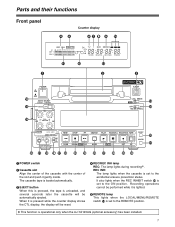
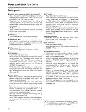
... ST CH2 AUDIO MON SELECT REW STOP FF SEARCH PLAY PAUSE/STILL REC(OPTION) TAPE RESET P PAGE DOWN MENU UP MODE s DATA r SET EE COUNTER O D E F BA G H I J K L M N 1 POWER switch 2 Cassette slot Align the center of the cassette with the center of the slot and push it is operational only when the AJ-YA120AG (optional accessory) has been installed. 7 CH 1 CH 2 REC INH REMOTE -30...
... ST CH2 AUDIO MON SELECT REW STOP FF SEARCH PLAY PAUSE/STILL REC(OPTION) TAPE RESET P PAGE DOWN MENU UP MODE s DATA r SET EE COUNTER O D E F BA G H I J K L M N 1 POWER switch 2 Cassette slot Align the center of the cassette with the center of the slot and push it is operational only when the AJ-YA120AG (optional accessory) has been installed. 7 CH 1 CH 2 REC INH REMOTE -30...
AJHD1200A User Guide
Page 8
... the menu settings or control the unit from the counter display mode used for either the video playback signals or audio playback signals has deteriorated. Level meter This indicates the levels of the output signals are supplied to the HD/SD REF VIDEO IN connector, this switch to perform on -screen information and other messages. Parts and their functions Front panel 6 REPEAT lamp This lights during playback. Red : This lights when correction or interpolation is locked. : Channel...
... the menu settings or control the unit from the counter display mode used for either the video playback signals or audio playback signals has deteriorated. Level meter This indicates the levels of the output signals are supplied to the HD/SD REF VIDEO IN connector, this switch to perform on -screen information and other messages. Parts and their functions Front panel 6 REPEAT lamp This lights during playback. Red : This lights when correction or interpolation is locked. : Channel...
AJHD1200A User Guide
Page 9
... accessory) has been installed. @ METER button and lamp (CH3•4) Each time the METER button is established. CH1/2 CH3/4 -- STEREO CH1+2 STEREO CH1+2 -- B Audio monitor selector switch This is used to which the signals are output are displayed, the CH3•4 lamp goes off , the HD SDI signal input or INT SG status is pressed, the signals which are input for the analog audio output connectors. A Audio output lamps (CH1•2, CH3•4) The audio channels to...
... accessory) has been installed. @ METER button and lamp (CH3•4) Each time the METER button is established. CH1/2 CH3/4 -- STEREO CH1+2 STEREO CH1+2 -- B Audio monitor selector switch This is used to which the signals are output are displayed, the CH3•4 lamp goes off , the HD SDI signal input or INT SG status is pressed, the signals which are input for the analog audio output connectors. A Audio output lamps (CH1•2, CH3•4) The audio channels to...
AJHD1200A User Guide
Page 10
... this to start playback. F Volume control This is operational only when the AJYA120AG (optional accessory) or AJ-YAD120AG (optional accessory) has been installed. 10 While the button is held down in one of the search modes (search still, FWD search, FWD search still or REV search still), the REV search mode is established, and the tape is reviewed at the speed selected using menu item NO.150 [SEARCH SPEED]. (See...
... this to start playback. F Volume control This is operational only when the AJYA120AG (optional accessory) or AJ-YAD120AG (optional accessory) has been installed. 10 While the button is held down in one of the search modes (search still, FWD search, FWD search still or REV search still), the REV search mode is established, and the tape is reviewed at the speed selected using menu item NO.150 [SEARCH SPEED]. (See...
AJHD1200A User Guide
Page 11
... DV connector (digital video interface). O COUNTER button This is set to select the signals which are displayed in the STOP mode. r : The remaining tape length and total tape length are to switch the counter display. P RESET button When this switch's position is displayed. The REC INHIBIT lamp on the cassette tape is used to be supplied from the tape are output as the VIDEO IN SEL setting, the audio input signals will...
... DV connector (digital video interface). O COUNTER button This is set to select the signals which are displayed in the STOP mode. r : The remaining tape length and total tape length are to switch the counter display. P RESET button When this switch's position is displayed. The REC INHIBIT lamp on the cassette tape is used to be supplied from the tape are output as the VIDEO IN SEL setting, the audio input signals will...
AJHD1200A User Guide
Page 12
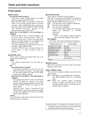
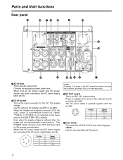
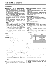
Parts and their functions Rear panel ? = 76 8 5 = AUDIO OUT CH 1 TC IN HD/SD REF VIDEO IN (OPTION) 1 75Ω ON (OPTION) OFF VIDEO OUT Y/G PB/B PR/R OUT CH 2 2(SUPER) PUASUHDIO CH IN 1 (OPTIPOUNS) H CH 2 AUDIO MON OUT L DC OUT 12V 250mA AC IN CH 3 CH 4 PUSH CH 3 PUSH CH 4 L R MONITOR FUSE 250V T2.5AH F1 R R E M O T E SIGNAL DC IN GND 3 > : 9 ;
Parts and their functions Rear panel ? = 76 8 5 = AUDIO OUT CH 1 TC IN HD/SD REF VIDEO IN (OPTION) 1 75Ω ON (OPTION) OFF VIDEO OUT Y/G PB/B PR/R OUT CH 2 2(SUPER) PUASUHDIO CH IN 1 (OPTIPOUNS) H CH 2 AUDIO MON OUT L DC OUT 12V 250mA AC IN CH 3 CH 4 PUSH CH 3 PUSH CH 4 L R MONITOR FUSE 250V T2.5AH F1 R R E M O T E SIGNAL DC IN GND 3 > : 9 ;
AJHD1200A User Guide
Page 13
... output signal level is fixed. < REMOTE CONTROL connector An external remote controller (AJ-95: optional accessory) is operational only when the AJYA120AG (optional accessory) has been installed. 13 Transmit Common Transmit B Receive A Frame Ground = Fan motor This is output from the VIDEO OUT2 connector. By selecting the menu item No.616 [OUT MATRIX] setting, Y/PB/PR or R/G/B signals can be selected as the HD analog component signals. Also, supply signals matching the input signals and...
... output signal level is fixed. < REMOTE CONTROL connector An external remote controller (AJ-95: optional accessory) is operational only when the AJYA120AG (optional accessory) has been installed. 13 Transmit Common Transmit B Receive A Frame Ground = Fan motor This is output from the VIDEO OUT2 connector. By selecting the menu item No.616 [OUT MATRIX] setting, Y/PB/PR or R/G/B signals can be selected as the HD analog component signals. Also, supply signals matching the input signals and...
AJHD1200A User Guide
Page 26
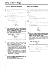
... video monitor. The unit is set to the LOAD position, and press the SET button. The unit is performed, the display returns to the menu screen without changing to the MENU position. OWhen the cursor is moved to USER (NOT SYSTEM) and this operation is now set to the default setting mode, and the default setting screen now appears on the video monitor. Setup (initial settings) Loading the user defaults Menu protection 1 Set the LOCAL/MENU/REMOTE switch to the user settings...
... video monitor. The unit is set to the LOAD position, and press the SET button. The unit is performed, the display returns to the menu screen without changing to the MENU position. OWhen the cursor is moved to USER (NOT SYSTEM) and this operation is now set to the default setting mode, and the default setting screen now appears on the video monitor. Setup (initial settings) Loading the user defaults Menu protection 1 Set the LOCAL/MENU/REMOTE switch to the user settings...
AJHD1200A User Guide
Page 32
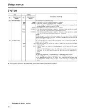
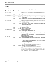
..., black signals are output from the SD output signals. To reflect a new setting in the unit. " " indicates the factory setting. 32 Superimposed display No. For selecting the output whose HD output phase is to be recorded and played back in the same way as the menu item No.600 [VIDEO IN SEL] setting or when an SD format tape is not reflected in the unit, turn off the power and then turn...
..., black signals are output from the SD output signals. To reflect a new setting in the unit. " " indicates the factory setting. 32 Superimposed display No. For selecting the output whose HD output phase is to be recorded and played back in the same way as the menu item No.600 [VIDEO IN SEL] setting or when an SD format tape is not reflected in the unit, turn off the power and then turn...
AJHD1200A User Guide
Page 35
... problem with the pictures which supports the setting, the field frequency is input to play back the signals including the HD REF signals. 1080i 0: 1080i mode 720p 1: 720p mode For setting the format in the format selected by the menu item No.020 [SYS FORMAT] setting. If this signal is not available, the unit's internal reference is supplied, the internal sync signal serves as the reference. HD-SP 1: The DVCPRO HD...
... problem with the pictures which supports the setting, the field frequency is input to play back the signals including the HD REF signals. 1080i 0: 1080i mode 720p 1: 720p mode For setting the format in the format selected by the menu item No.020 [SYS FORMAT] setting. If this signal is not available, the unit's internal reference is supplied, the internal sync signal serves as the reference. HD-SP 1: The DVCPRO HD...
AJHD1200A User Guide
Page 37
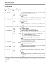
... to the 9-pin remote connector. For selecting the output signals in the shuttle mode when using the external controller connected to the position of the TAPE/EE switch. " " indicates the factory setting. 37 For setting the video and audio output statuses during recording2, including follow-on recording, and playback regardless of settings 101 SHTL MAX 0000 0001 0002 102 FF.REW MAX 0000 0001 0002 104 REF ALARM 106 EJECT...
... to the 9-pin remote connector. For selecting the output signals in the shuttle mode when using the external controller connected to the position of the TAPE/EE switch. " " indicates the factory setting. 37 For setting the video and audio output statuses during recording2, including follow-on recording, and playback regardless of settings 101 SHTL MAX 0000 0001 0002 102 FF.REW MAX 0000 0001 0002 104 REF ALARM 106 EJECT...
AJHD1200A User Guide
Page 38
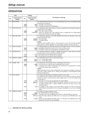
... BEGIN point, and plays back, and this menu item. OFF 1: The EJECT button can be used. (For setting the AUTO BACK function operation which has been recorded using a format other trouble, the "0" setting (no AUTO BACK). M-STOP 1: The tape stops near the BEGIN point when it is to be trouble-free. Superimposed display 110 AUTO REW 112 FRZ MODE SEL 114 REC INH LAMP 115 EJECT...
... BEGIN point, and plays back, and this menu item. OFF 1: The EJECT button can be used. (For setting the AUTO BACK function operation which has been recorded using a format other trouble, the "0" setting (no AUTO BACK). M-STOP 1: The tape stops near the BEGIN point when it is to be trouble-free. Superimposed display 110 AUTO REW 112 FRZ MODE SEL 114 REC INH LAMP 115 EJECT...
AJHD1200A User Guide
Page 41
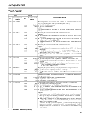
... time code reader is used . O This setting takes effect only with the SD output (VIDEO output and SD SDI output). FREE 1: The generator runs while the power is on recording mode: REGEN is used . UB 2: Only the user's bit is output. SLTC 2: The LTC information added to the HD SDI IN connector is read from the time code. Setup menus TIME CODE Item Setting No. Superimposed display No. Superimposed display Description of the unit's operation mode. THRU 1: The VITC signal...
... time code reader is used . O This setting takes effect only with the SD output (VIDEO output and SD SDI output). FREE 1: The generator runs while the power is on recording mode: REGEN is used . UB 2: Only the user's bit is output. SLTC 2: The LTC information added to the HD SDI IN connector is read from the time code. Setup menus TIME CODE Item Setting No. Superimposed display No. Superimposed display Description of the unit's operation mode. THRU 1: The VITC signal...
AJHD1200A User Guide
Page 47
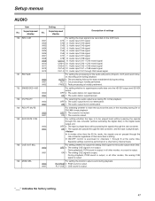
... audio data is attenuated. During playback, PCM sound is output; Superimposed display Description of this menu item's setting. Setup menus AUDIO Item No. During playback, PCM sound is output; OFF 0: The tape is output. ON 1: The signals are not passed through 8 at the joins in all other modes, the analog CUE signal is exercised for the audio edit points (IN point, OUT point) and followon recording point...
... audio data is attenuated. During playback, PCM sound is output; Superimposed display Description of this menu item's setting. Setup menus AUDIO Item No. During playback, PCM sound is output; OFF 0: The tape is output. ON 1: The signals are not passed through 8 at the joins in all other modes, the analog CUE signal is exercised for the audio edit points (IN point, OUT point) and followon recording point...
AJHD1200A User Guide
Page 49
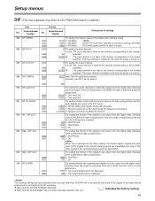
... the digital video interface output. Setup menus DIF (This menu appears only when the AJ-YAD120AG board is not displayed. AUTO 64: The input channel is installed). CH1/2 0: CH1 and CH2 CH3/4 1: CH3 and CH4 For setting forcible audio mode conversion when a DV tape is fixed at the channel corresponding to the number specified. HD 0: DVCPRO HD 50M 1: DVCPRO50 DV 2: DV For setting the format of the signals to be output...
... the digital video interface output. Setup menus DIF (This menu appears only when the AJ-YAD120AG board is not displayed. AUTO 64: The input channel is installed). CH1/2 0: CH1 and CH2 CH3/4 1: CH3 and CH4 For setting forcible audio mode conversion when a DV tape is fixed at the channel corresponding to the number specified. HD 0: DVCPRO HD 50M 1: DVCPRO50 DV 2: DV For setting the format of the signals to be output...
AJHD1200A User Guide
Page 50
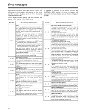
... the error number flashes, and the unit is performed in the DF mode. Wait with the unit, the time code must be operated. NO RF This appears when a blank area on the monitor's superimposed display. O Playback data cannot be recorded in the EJECT mode, the cylinder starts rotating ...ERROR RATE This appears when the error rate has deteriorated, and either the video or audio playback signals are no response from any of the time code must be read. Error No. The VTR continues to be uniform (it resumes rotating. The information of the system control microcomputer even after the unit...
... the error number flashes, and the unit is performed in the DF mode. Wait with the unit, the time code must be operated. NO RF This appears when a blank area on the monitor's superimposed display. O Playback data cannot be recorded in the EJECT mode, the cylinder starts rotating ...ERROR RATE This appears when the error rate has deteriorated, and either the video or audio playback signals are no response from any of the time code must be read. Error No. The VTR continues to be uniform (it resumes rotating. The information of the system control microcomputer even after the unit...
AJHD1200A User Guide
Page 54
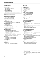
.../50 Hz switchable Recording audio signals21: 48 kHz, 16 bits, 8 channels Recording tracks21: O Digital video/audio: Helical track O Time code: Helical track (sub code area) O Cue signal: 1 track O Control (CTL) signal: 1 track Playback formats: DVCPRO HD-LP, DVCPRO HD, DVCPRO50, DVCPRO P, DVCPRO, DV-SP, DVCAM Tape speed: 67.64 mm/sec. (in 59.94 Hz mode) 67.70 mm/sec. (in 60/50 Hz mode) Recording time: 92 min. (when using AJ-HP92ELG) Tapes...
.../50 Hz switchable Recording audio signals21: 48 kHz, 16 bits, 8 channels Recording tracks21: O Digital video/audio: Helical track O Time code: Helical track (sub code area) O Cue signal: 1 track O Control (CTL) signal: 1 track Playback formats: DVCPRO HD-LP, DVCPRO HD, DVCPRO50, DVCPRO P, DVCPRO, DV-SP, DVCAM Tape speed: 67.64 mm/sec. (in 59.94 Hz mode) 67.70 mm/sec. (in 60/50 Hz mode) Recording time: 92 min. (when using AJ-HP92ELG) Tapes...


