
AJHDC27A User Guide
Page 3
... 47 Adjusting the black balance 51 Setting the electronic shutter 52 Shutter modes 52 Setting the shutter mode and speed 52 Changing the shutter speed and mode selection range 53 Setting the synchro scan mode 53 Adjusting the audio level 54 Manual audio level adjustments 54 Limiter 54 Setting the time data 55 Setting the user's bit 55 Setting the time code 56 Externally locking the time code 57 How to use the user data 58 Setup card operations 59 Formatting the setup card 60 Saving the data settings...
... 47 Adjusting the black balance 51 Setting the electronic shutter 52 Shutter modes 52 Setting the shutter mode and speed 52 Changing the shutter speed and mode selection range 53 Setting the synchro scan mode 53 Adjusting the audio level 54 Manual audio level adjustments 54 Limiter 54 Setting the time data 55 Setting the user's bit 55 Setting the time code 56 Externally locking the time code 57 How to use the user data 58 Setup card operations 59 Formatting the setup card 60 Saving the data settings...
AJHDC27A User Guide
Page 5
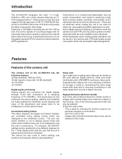
... the picture quality, stability and reliability but it is extremely dust-proof and moisture-proof. Furthermore, it also enables the viewfinder screen displays and many of problem. Small multimedia cards meeting global standards can accomplish data management. Customized setting menus The status displays, messages and marker displays are controlled using setting menus which can be used for the camera and VTR setting data as setup cards. O Synchro scan mode This...
... the picture quality, stability and reliability but it is extremely dust-proof and moisture-proof. Furthermore, it also enables the viewfinder screen displays and many of problem. Small multimedia cards meeting global standards can accomplish data management. Customized setting menus The status displays, messages and marker displays are controlled using setting menus which can be used for the camera and VTR setting data as setup cards. O Synchro scan mode This...
AJHDC27A User Guide
Page 6
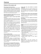
... balance. (Using menu settings, this button. O Built-in 4-line image enhancer O Built-in the memory even after the power has been turned off so that the picture quality will be high, the unit is turned on the viewfinder screen. Generation of color bar signals and reference audio signals The unit contains a circuit for achieving a wide dynamic range through which strong signals can pass. The adjustment settings remain stored...
... balance. (Using menu settings, this button. O Built-in 4-line image enhancer O Built-in the memory even after the power has been turned off so that the picture quality will be high, the unit is turned on the viewfinder screen. Generation of color bar signals and reference audio signals The unit contains a circuit for achieving a wide dynamic range through which strong signals can pass. The adjustment settings remain stored...
AJHDC27A User Guide
Page 7
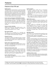
... the VTR START button or lens VTR button, continuity between the scenes is rewound to the start key acknowledgment time, the unit can be attached. External locking of microphone (optional accessory) with a nature theme or art programs. ODolby noise reduction manufactured under license from Dolby Laboratories Licensing Corporation. Audio functions OA phantom power supply type of time code The built-in DOLBY NR system The cue audio recording circuitry...
... the VTR START button or lens VTR button, continuity between the scenes is rewound to the start key acknowledgment time, the unit can be attached. External locking of microphone (optional accessory) with a nature theme or art programs. ODolby noise reduction manufactured under license from Dolby Laboratories Licensing Corporation. Audio functions OA phantom power supply type of time code The built-in DOLBY NR system The cue audio recording circuitry...
AJHDC27A User Guide
Page 9
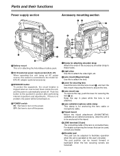
... be adjusted to facilitate operation when the unit is operated on the power. Push this button to the tripod. 8 LENS terminal (12-pin) The connecting cable of the accessory shoulder strap to these hooks. 2 Light shoe Use this to attach the video light, etc. 3 Lens mount (Bayonet type) Use this to attach the lens. 4 Lever for securing lens Insert the lens into the lens mount 3, and turn on the user...
... be adjusted to facilitate operation when the unit is operated on the power. Push this button to the tripod. 8 LENS terminal (12-pin) The connecting cable of the accessory shoulder strap to these hooks. 2 Light shoe Use this to attach the video light, etc. 3 Lens mount (Bayonet type) Use this to attach the lens. 4 Lever for securing lens Insert the lens into the lens mount 3, and turn on the user...
AJHDC27A User Guide
Page 11
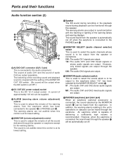
... its lowest setting. =MONITOR SELECT (audio channel selector) switch This is used to adjust the volume of the warning lamps and warning displays. However, when the earphone is capable of audio CH2 are not audible when this speaker. ST : The audio CH1 and CH2 stereo audio signals are output. ? The warning alarms are output separately. Parts and their functions Audio function section (2) => < : ; < Speaker The EE sound during recording or the playback sound during...
... its lowest setting. =MONITOR SELECT (audio channel selector) switch This is used to adjust the volume of the warning lamps and warning displays. However, when the earphone is capable of audio CH2 are not audible when this speaker. ST : The audio CH1 and CH2 stereo audio signals are output. ? The warning alarms are output separately. Parts and their functions Audio function section (2) => < : ; < Speaker The EE sound during recording or the playback sound during...
AJHDC27A User Guide
Page 13
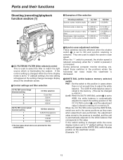
...) 2 Synchro scan adjustment switches These switches become effective when the shutter switch 7 is set to "3" (default setting), the new setting will appear at the WHITE BAL switch display position on the viewfinder screen. (Example: "A") 13 conversely, when the "+" switch is pressed, it is reduced; The 3200 K white balance value is stored in the memory. (This can be changed while the menu display mode is set to match the light source...
...) 2 Synchro scan adjustment switches These switches become effective when the shutter switch 7 is set to "3" (default setting), the new setting will appear at the WHITE BAL switch display position on the viewfinder screen. (Example: "A") 13 conversely, when the "+" switch is pressed, it is reduced; The 3200 K white balance value is stored in the memory. (This can be changed while the menu display mode is set to match the light source...
AJHDC27A User Guide
Page 15
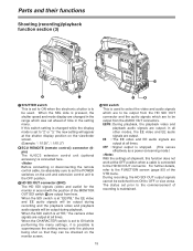
... mode display are changed while the display mode is set to "2" or "3," the new setting will be switched from the AUDIO OUT connectors. If this function does not work at the OFF position when a cable is connected to the HD SDI OUT connector. EE : The EE video and EE audio signals are output at the shutter display position on the monitor screen. : SDI switch This is used . During recording, the HD SDI OUT output signals cannot be output during recording...
... mode display are changed while the display mode is set to "2" or "3," the new setting will be switched from the AUDIO OUT connectors. If this function does not work at the OFF position when a cable is connected to the HD SDI OUT connector. EE : The EE video and EE audio signals are output at the shutter display position on the monitor screen. : SDI switch This is used . During recording, the HD SDI OUT output signals cannot be output during recording...
AJHDC27A User Guide
Page 37
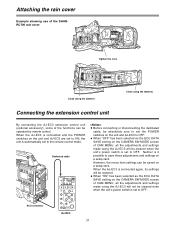
... is connected and the POWER switches on the CAMERA SW MODE screen of the functions can be saved on a setup card. O When "OFF" has been selected as the ECU DATA SAVE setting on the unit and AJ-EC3 are set to ON, the unit is automatically set to OFF. Connecting the extension control unit By connecting the AJ-EC3 extension control unit (optional accessory), some of CAM MENU, all the adjustments and settings made using...
... is connected and the POWER switches on the CAMERA SW MODE screen of the functions can be saved on a setup card. O When "OFF" has been selected as the ECU DATA SAVE setting on the unit and AJ-EC3 are set to ON, the unit is automatically set to OFF. Connecting the extension control unit By connecting the AJ-EC3 extension control unit (optional accessory), some of CAM MENU, all the adjustments and settings made using...
AJHDC27A User Guide
Page 38
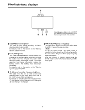
... lights when the battery is the AJ-HVF27P (For details concerning the viewfinder, refer to the section on the "!LED" screen of the viewfinder.) 1 TALLY/REC (recording) lamp This lights up (red) during recording. For details on selecting the items targeted for the pause timer (temporary stop time) has elapsed. Viewfinder lamp displays 1 TALLY / REC BATT VTR SAVE 32 4 Viewfinder pictured...
... lights when the battery is the AJ-HVF27P (For details concerning the viewfinder, refer to the section on the "!LED" screen of the viewfinder.) 1 TALLY/REC (recording) lamp This lights up (red) during recording. For details on selecting the items targeted for the pause timer (temporary stop time) has elapsed. Viewfinder lamp displays 1 TALLY / REC BATT VTR SAVE 32 4 Viewfinder pictured...
AJHDC27A User Guide
Page 41
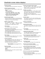
... MODE CHECK button is set to 99. 6 White balance memory display This indicates the automatic adjustment memory selected for audio CH1 and CH2). Audio level display + VTR's level meter -40 -30 -25 -18/20 -15 -10 -5 0 9 Aperture display This indicates the approximate aperture setting (F number). C Total tape length This indicates the total length of the viewfinder screen. F Interval recording mode display (flashing) G AUDIO CH1/CH2 input display The input signals to "A." The display...
... MODE CHECK button is set to 99. 6 White balance memory display This indicates the automatic adjustment memory selected for audio CH1 and CH2). Audio level display + VTR's level meter -40 -30 -25 -18/20 -15 -10 -5 0 9 Aperture display This indicates the approximate aperture setting (F number). C Total tape length This indicates the total length of the viewfinder screen. F Interval recording mode display (flashing) G AUDIO CH1/CH2 input display The input signals to "A." The display...
AJHDC27A User Guide
Page 44
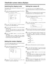
... signals are output. 1 Perform the menu operations (pages 70 to 72) to open the "VF DISPLAY" screen. Viewfinder screen status displays Switching the display mode The display mode settings are switched on the VF INDICATOR screen has been set to "ON." 44 n< CAMERA ID > m ID : 3 When the JOG dial button is pressed, the arrow (cursor) flashes, and the input mode is switched in the following sequence: Space: ) 7 letters: A-Z 7 numbers: 0-9 7 symbols 5 Press the JOG dial button...
... signals are output. 1 Perform the menu operations (pages 70 to 72) to open the "VF DISPLAY" screen. Viewfinder screen status displays Switching the display mode The display mode settings are switched on the VF INDICATOR screen has been set to "ON." 44 n< CAMERA ID > m ID : 3 When the JOG dial button is pressed, the arrow (cursor) flashes, and the input mode is switched in the following sequence: Space: ) 7 letters: A-Z 7 numbers: 0-9 7 symbols 5 Press the JOG dial button...
AJHDC27A User Guide
Page 49
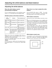
.... When the FILTER INH setting on the CAMERA SW MODE screen of CAM MENU is ON (default setting), the number of memories for set A and set the white balance search area to either 90% or 50% by changing the AWB AREA setting on the viewfinder screen (when "2" or "3" has been set to OFF, the adjustment values for each . posture, etc.). If the error message persists even after...
.... When the FILTER INH setting on the CAMERA SW MODE screen of CAM MENU is ON (default setting), the number of memories for set A and set the white balance search area to either 90% or 50% by changing the AWB AREA setting on the viewfinder screen (when "2" or "3" has been set to OFF, the adjustment values for each . posture, etc.). If the error message persists even after...
AJHDC27A User Guide
Page 58
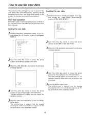
... press the JOG dial button. The data settings are saved in the user area of the camera's memory. 4 Turn the JOG dial button to move the arrow (cursor) to YES, and press the JOG dial button. Loading the user data 1 Perform the menu operations (pages 70 to 72), and display the "CAM CARD READ/WRITE" screen of CAM MAIN MENU 4. How to use the user data The contents of...
... press the JOG dial button. The data settings are saved in the user area of the camera's memory. 4 Turn the JOG dial button to move the arrow (cursor) to YES, and press the JOG dial button. Loading the user data 1 Perform the menu operations (pages 70 to 72), and display the "CAM CARD READ/WRITE" screen of CAM MAIN MENU 4. How to use the user data The contents of...
AJHDC27A User Guide
Page 71
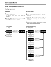
...MENU button. } CAM USER MENU 5 Press the MENU button. 5 VTR USER MENU } Press the JOG dial button. The camera unit's USER menu screen is displayed. 2 When the MENU button is pressed again, the VTR unit's USER menu screen is displayed. Menu operations Basic setting menu operations Displaying menus User menu: Engineer menu 1 Press the MENU button. Hold down the MENU button for at least 3 seconds. 2 When the JOG dial button is pressed, the next MAIN menu screen (of the camera unit) is displayed. 3 When the MENU button is pressed, the VTR unit's MAIN MENU screen is displayed...
...MENU button. } CAM USER MENU 5 Press the MENU button. 5 VTR USER MENU } Press the JOG dial button. The camera unit's USER menu screen is displayed. 2 When the MENU button is pressed again, the VTR unit's USER menu screen is displayed. Menu operations Basic setting menu operations Displaying menus User menu: Engineer menu 1 Press the MENU button. Hold down the MENU button for at least 3 seconds. 2 When the JOG dial button is pressed, the next MAIN menu screen (of the camera unit) is displayed. 3 When the MENU button is pressed, the VTR unit's MAIN MENU screen is displayed...
AJHDC27A User Guide
Page 72
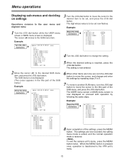
... GAMMA CAMERA SETTING 2 Move the cursor (n) to be set now flashes. The USER menu screen or MAIN menu screen is now displayed. (The cursor appears in the title part of the settings, press the MENU button. To exit the camera unit's menu, press the MENU button twice. The SUB menu is now displayed so proceed with operation by repeating steps 3 to 5. 7 To move to another SUB menu, turn the JOG dial button to be set , and...
... GAMMA CAMERA SETTING 2 Move the cursor (n) to be set now flashes. The USER menu screen or MAIN menu screen is now displayed. (The cursor appears in the title part of the settings, press the MENU button. To exit the camera unit's menu, press the MENU button twice. The SUB menu is now displayed so proceed with operation by repeating steps 3 to 5. 7 To move to another SUB menu, turn the JOG dial button to be set , and...
AJHDC27A User Guide
Page 82
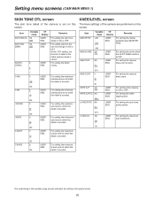
... the detail is boosted. For setting the auto knee point position. Setting menu screens (CAM MAIN MENU 1) SKIN TONE DTL screen The skin tone detail of the camera is set on this screen. For setting the manual knee slope. The underlining in the variable range column indicates the setting in the skin tone range to ON or OFF. For setting the medium Iaxis level at which...
... the detail is boosted. For setting the auto knee point position. Setting menu screens (CAM MAIN MENU 1) SKIN TONE DTL screen The skin tone detail of the camera is set on this screen. For setting the manual knee slope. The underlining in the variable range column indicates the setting in the skin tone range to ON or OFF. For setting the medium Iaxis level at which...
AJHDC27A User Guide
Page 87
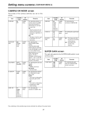
....), NORMAL (normal speed: approx. 1 sec.) or SLOW (slow: approx. 3 sec.) can be held for each of the camera switches are set on this screen. Item USER2 SW S. For setting the super black level. ON : The data controlled by changing the L/M/H switch setting. Item S. GAIN VALUE Variable VF range display 18dB USER 24dB ENG 30dB 36dB Remarks For selecting the gain when the SUPER GAIN...
....), NORMAL (normal speed: approx. 1 sec.) or SLOW (slow: approx. 3 sec.) can be held for each of the camera switches are set on this screen. Item USER2 SW S. For setting the super black level. ON : The data controlled by changing the L/M/H switch setting. Item S. GAIN VALUE Variable VF range display 18dB USER 24dB ENG 30dB 36dB Remarks For selecting the gain when the SUPER GAIN...
AJHDC27A User Guide
Page 102
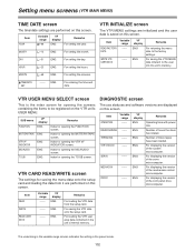
... saving the VTR data onto the setup card. For loading the VTR user area data contained in the preset mode. 102 VTR USER MENU SELECT screen This is saved on this screen. DIAGNOSTIC screen The use statuses and software versions are performed on this screen. Item YEAR Variable VF range display 00-99 ENG Remarks For setting the year. Number of the mechanism control microcomputer. For displaying the version of...
... saving the VTR data onto the setup card. For loading the VTR user area data contained in the preset mode. 102 VTR USER MENU SELECT screen This is saved on this screen. DIAGNOSTIC screen The use statuses and software versions are performed on this screen. Item YEAR Variable VF range display 00-99 ENG Remarks For setting the year. Number of the mechanism control microcomputer. For displaying the version of...
AJHDC27A User Guide
Page 110
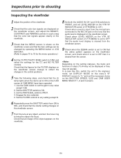
..., switch the unit to the engineer mode, set DISPLAY MODE on the menu's VF DISPLAY screen to "3," and set to OFF that it is set the necessary items on the SHUTTER SPEED, !LED and CAM USER MENU SELECT 1, 2 and 3 screens. 6 Repeatedly press the SHUTTER switch from the microphone connected to the MIC IN jack on the lens that the audio level is displayed on the viewfinder. 110 Check when sound is input from...
..., switch the unit to the engineer mode, set DISPLAY MODE on the menu's VF DISPLAY screen to "3," and set to OFF that it is set the necessary items on the SHUTTER SPEED, !LED and CAM USER MENU SELECT 1, 2 and 3 screens. 6 Repeatedly press the SHUTTER switch from the microphone connected to the MIC IN jack on the lens that the audio level is displayed on the viewfinder. 110 Check when sound is input from...


