
AJHDC27A User Guide
Page 1
Camera/VTR AJ- P Operating Instructions
Camera/VTR AJ- P Operating Instructions
AJHDC27A User Guide
Page 3
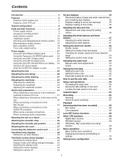
.../status display section 18 Menu operation section 19 Time code related section 19 Power supply 21 Using the Anton/Bauer battery pack 21 Using the Panasonic AU-BP402 battery pack . . .22 Using the Sony NP-1 battery pack 23 Using the Sony BP-90 battery pack 23 Using the Sony ... the display items 42 Display modes and setting change messages . . .43 Switching the display mode 44 Setting the marker displays 44 Setting the camera ID 44 Screen displays 45 Remaining battery charge and audio channel level and remaining tape displays 45 Displays relating to errors and warnings 45 Displays...
.../status display section 18 Menu operation section 19 Time code related section 19 Power supply 21 Using the Anton/Bauer battery pack 21 Using the Panasonic AU-BP402 battery pack . . .22 Using the Sony NP-1 battery pack 23 Using the Sony BP-90 battery pack 23 Using the Sony ... the display items 42 Display modes and setting change messages . . .43 Switching the display mode 44 Setting the marker displays 44 Setting the camera ID 44 Screen displays 45 Remaining battery charge and audio channel level and remaining tape displays 45 Displays relating to errors and warnings 45 Displays...

AJHDC27A User Guide
Page 4
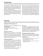
... screen 83 CAM MAIN MENU 2 VF DISPLAY screen 84 VF MARKER screen 84 VF INDICATOR screen 85 CAMERA ID screen 85 SHUTTER SPEED screen 86 !LED screen 86 CAMERA SW MODE screen 87 SUPER GAIN screen 87 CAM MAIN MENU 3 CAM CARD READ/WRITE screen 88 CAM CARD ... 108 Condensation 108 Head cleaning 108 Cleaning inside the viewfinder 108 Phenomena inherent to CCD cameras 108 Replacing the backup battery 108 Inspections prior to shooting 109 Preparation for inspection 109 Inspecting the camera unit 109 Inspecting the viewfinder 110 Inspecting the aperture and zoom functions . . .111...
... screen 83 CAM MAIN MENU 2 VF DISPLAY screen 84 VF MARKER screen 84 VF INDICATOR screen 85 CAMERA ID screen 85 SHUTTER SPEED screen 86 !LED screen 86 CAMERA SW MODE screen 87 SUPER GAIN screen 87 CAM MAIN MENU 3 CAM CARD READ/WRITE screen 88 CAM CARD ... 108 Condensation 108 Head cleaning 108 Cleaning inside the viewfinder 108 Phenomena inherent to CCD cameras 108 Replacing the backup battery 108 Inspections prior to shooting 109 Preparation for inspection 109 Inspecting the camera unit 109 Inspecting the viewfinder 110 Inspecting the aperture and zoom functions . . .111...
AJHDC27A User Guide
Page 5
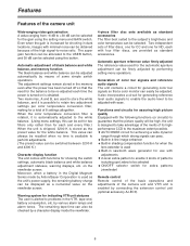
... for the camera and VTR setting data as well. O Synchro scan mode This is also enhanced. O High sensitivity: 2000 lux (F10) O High signal-to the next. These are also used for shooting the monitor screens of HD TV (720P/59.94 Hz), and 2) a DVCPRO HD format VTR ...using setting menus which tells the user that incorporates the latest compression technology. Introduction The AJ-HDC27A integrates two units: 1) a highdefinition (HD) color video camera featuring an ITCCD equipped with a 1 million pixel on SD card (Secure Digital Memory Card) and small multimedia cards (VW-MMT8) ...
... for the camera and VTR setting data as well. O Synchro scan mode This is also enhanced. O High sensitivity: 2000 lux (F10) O High signal-to the next. These are also used for shooting the monitor screens of HD TV (720P/59.94 Hz), and 2) a DVCPRO HD format VTR ...using setting menus which tells the user that incorporates the latest compression technology. Introduction The AJ-HDC27A integrates two units: 1) a highdefinition (HD) color video camera featuring an ITCCD equipped with a 1 million pixel on SD card (Secure Digital Memory Card) and small multimedia cards (VW-MMT8) ...
AJHDC27A User Guide
Page 6
... by connecting the extension control unit (optional accessory AJ-EC3). 6 This value can be recalled when no time is enabled by means of the camera unit Wide-ranging video gain selection A value ranging from -6 dB to perform adjustments. (The preset value can always be switched between 3200 K ...noise can be displayed as the preset value for zebra patterns (viewfinder) Remote control Remote control of the basic operations and adjustments of the camera unit and VTR unit is available to +30 dB can be selected. Two memories, A and B, are provided as standard accessories The ...
... by connecting the extension control unit (optional accessory AJ-EC3). 6 This value can be recalled when no time is enabled by means of the camera unit Wide-ranging video gain selection A value ranging from -6 dB to perform adjustments. (The preset value can always be switched between 3200 K ...noise can be displayed as the preset value for zebra patterns (viewfinder) Remote control Remote control of the basic operations and adjustments of the camera unit and VTR unit is available to +30 dB can be selected. Two memories, A and B, are provided as standard accessories The ...

AJHDC27A User Guide
Page 8
.../CANON Rain cover SHAN-RC700 Soft carrying case AJ-SC900 Tripod mount adapter SHAN-TM700 Extension control unit AJ-EC3 Camera/VTR AJ-HDC27A Battery case AU-M402H Battery case/Battery holder Panasonic Battery AU-BP402 AJ-BP490 Anton/Bauer Battery Sony Battery BP-90 BP-L60/L90 NP-1 Battery charger AG...
.../CANON Rain cover SHAN-RC700 Soft carrying case AJ-SC900 Tripod mount adapter SHAN-TM700 Extension control unit AJ-EC3 Camera/VTR AJ-HDC27A Battery case AU-M402H Battery case/Battery holder Panasonic Battery AU-BP402 AJ-BP490 Anton/Bauer Battery Sony Battery BP-90 BP-L60/L90 NP-1 Battery charger AG...

AJHDC27A User Guide
Page 12
Parts and their functions Viewfinder section >
Parts and their functions Viewfinder section >

AJHDC27A User Guide
Page 14
...BAL switch is pressed continuously for 8 seconds or more on the ABB side. The AUTO KNEE function can be recorded The pictures shot by the camera are output. Use this , the background can be stopped. The adjusted value in this case is stored in a dedicated memory. The adjusted .../black balance adjustment) switch AWB: This is selected when the white balance is set to the L, M and H settings are specified by the camera are output. AUTO KNEE function If the level is adjusted to be adjusted automatically. AUTO KNEE OFF CAM. MANUAL KNEE is very bright, the ...
...BAL switch is pressed continuously for 8 seconds or more on the ABB side. The AUTO KNEE function can be recorded The pictures shot by the camera are output. Use this , the background can be stopped. The adjusted value in this case is stored in a dedicated memory. The adjusted .../black balance adjustment) switch AWB: This is selected when the white balance is set to the L, M and H settings are specified by the camera are output. AUTO KNEE function If the level is adjusted to be adjusted automatically. AUTO KNEE OFF CAM. MANUAL KNEE is very bright, the ...
AJHDC27A User Guide
Page 15
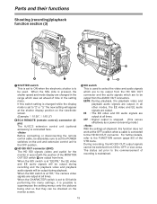
... FUNCTION screen (page 95) of recording is to be used to select the video and audio signals which are output; During recording, the HD SDI OUT output signals cannot be switched from here. Before connecting or disconnecting the remote control cable, be absolutely sure to set the POWER... screen. (Example: ": 1/120", ": 1/61.2") 8ECU REMOTE (remote control) connector (6pin) The AJ-EC3 extension control unit (optional accessory) is at "EE," the camera video signals are output at all other modes, the EE video and EE audio signals are output at all times. in the setting menu. When...
... FUNCTION screen (page 95) of recording is to be used to select the video and audio signals which are output; During recording, the HD SDI OUT output signals cannot be switched from here. Before connecting or disconnecting the remote control cable, be absolutely sure to set the POWER... screen. (Example: ": 1/120", ": 1/61.2") 8ECU REMOTE (remote control) connector (6pin) The AJ-EC3 extension control unit (optional accessory) is at "EE," the camera video signals are output at all other modes, the EE video and EE audio signals are output at all times. in the setting menu. When...

AJHDC27A User Guide
Page 17
... comes on during rewinding. The button's lamp comes on during fast forwarding. USER 1 and USER 2 buttons A user setting can be allocated to each of the camera. ? When the button is pressed again, the selected mode is released. @ EJECT button This is selected. A REW button This is pressed to stop (STOP)..., the tape will cause the cassette to be cued (fast forwarded and played back) at the same time: this button is held down, the camera's setting mode is set to pause in the pause mode for two minutes, it is pressed during playback. When it is pressed during playback, the...
... comes on during rewinding. The button's lamp comes on during fast forwarding. USER 1 and USER 2 buttons A user setting can be allocated to each of the camera. ? When the button is pressed again, the selected mode is released. @ EJECT button This is selected. A REW button This is pressed to stop (STOP)..., the tape will cause the cassette to be cued (fast forwarded and played back) at the same time: this button is held down, the camera's setting mode is set to pause in the pause mode for two minutes, it is pressed during playback. When it is pressed during playback, the...

AJHDC27A User Guide
Page 19
... B 0dB C Z73 Press the MENU button. ¢¢¢¢ CAM USER MENU ¢¢¢¢ Camera unit's user menu 32 1 GENLOCK IN connector (BNC) Supply the analog HD reference signal to this connector for the user menu can be changed to suit the desired objective. For details on... the menu operation method, refer to "Menu operations" on the USER MENU SELECT screen. The selection of the menu for gen-locking the camera unit or when...
... B 0dB C Z73 Press the MENU button. ¢¢¢¢ CAM USER MENU ¢¢¢¢ Camera unit's user menu 32 1 GENLOCK IN connector (BNC) Supply the analog HD reference signal to this connector for the user menu can be changed to suit the desired objective. For details on... the menu operation method, refer to "Menu operations" on the USER MENU SELECT screen. The selection of the menu for gen-locking the camera unit or when...

AJHDC27A User Guide
Page 25
... clamp, and connect it the mount cap. Lens flange back adjustment 2. Mark LENS socket OFor details on the lens mounted. 1. OThe following lens adjustments and camera adjustments may be necessary depending on handling the lens, refer to the operating instructions which accompany the lens.
... clamp, and connect it the mount cap. Lens flange back adjustment 2. Mark LENS socket OFor details on the lens mounted. 1. OThe following lens adjustments and camera adjustments may be necessary depending on handling the lens, refer to the operating instructions which accompany the lens.

AJHDC27A User Guide
Page 26
... surface to the telephoto position either manually or electrically. 26 Adjustment method For details on the adjustment method and lens positions, refer also to the camera. Once this process. 8 Repeat steps 5 to adjust the focus.
... surface to the telephoto position either manually or electrically. 26 Adjustment method For details on the adjustment method and lens positions, refer also to the camera. Once this process. 8 Repeat steps 5 to adjust the focus.

AJHDC27A User Guide
Page 27
... for ZEBRA to "L (0 dB)." OEven when the white shading has been adjusted, tinting may be necessary. This is a phenomenon which does not tend to the camera. At this stage, do not forget to connect the lens cable. 2 Set the electronic shutter to OFF, and set the gain to fill part of...
... for ZEBRA to "L (0 dB)." OEven when the white shading has been adjusted, tinting may be necessary. This is a phenomenon which does not tend to the camera. At this stage, do not forget to connect the lens cable. 2 Set the electronic shutter to OFF, and set the gain to fill part of...

AJHDC27A User Guide
Page 29
... the viewfinder (The viewfinder is an optional accessory.) Attaching the viewfinder Detaching the viewfinder 1 1 Check that the camera's POWER switch is at OFF. 2 Connect the plug to the viewfinder connecting terminal. Check that the camera's POWER switch is at OFF. Stopper screw 3 Push the viewfinder down. 3 Disconnect the plug from the viewfinder...
... the viewfinder (The viewfinder is an optional accessory.) Attaching the viewfinder Detaching the viewfinder 1 1 Check that the camera's POWER switch is at OFF. 2 Connect the plug to the viewfinder connecting terminal. Check that the camera's POWER switch is at OFF. Stopper screw 3 Push the viewfinder down. 3 Disconnect the plug from the viewfinder...

AJHDC27A User Guide
Page 31
AUDIO IN switches MIC IN jack 31 Mic holder 2 Attach the microphone, and tighten the locking screw. Locking screw 3 Connect the microphone's connecting cable to the viewfinder. 1 Open the mic holder. Audio input preparation When attaching a microphone to the viewfinder (optional accessory) for use The microphone of the AJ-MC700P mic kit (optional accessory) can be recorded. AJ-HVF27P 4 Set the AUDIO IN switch or switches to "FRONT" in accordance with the audio channel or channels whose sound is to be attached to the MIC IN jack on the camera.
AUDIO IN switches MIC IN jack 31 Mic holder 2 Attach the microphone, and tighten the locking screw. Locking screw 3 Connect the microphone's connecting cable to the viewfinder. 1 Open the mic holder. Audio input preparation When attaching a microphone to the viewfinder (optional accessory) for use The microphone of the AJ-MC700P mic kit (optional accessory) can be recorded. AJ-HVF27P 4 Set the AUDIO IN switch or switches to "FRONT" in accordance with the audio channel or channels whose sound is to be attached to the MIC IN jack on the camera.

AJHDC27A User Guide
Page 32
... the screws provided with the audio channel or channels whose sound is to be recorded. 3 Attach the microphone to the MIC IN jack on the camera. Locking screw AUDIO IN switches 32 Audio input preparation When attaching a microphone to the main unit for use Attaching the AJ-MH700P mic holder (optional...
... the screws provided with the audio channel or channels whose sound is to be recorded. 3 Attach the microphone to the MIC IN jack on the camera. Locking screw AUDIO IN switches 32 Audio input preparation When attaching a microphone to the main unit for use Attaching the AJ-MH700P mic holder (optional...

AJHDC27A User Guide
Page 33
... IN switches When the LINE/MIC/+48V selector switch is set to the AUDIO IN connector on the camera. 1 Connect the microphone's connecting cable to "+48V," the phantom power supply system is to be connected to "REAR." Two microphones can be recorded. AUDIO IN ...
... IN switches When the LINE/MIC/+48V selector switch is set to the AUDIO IN connector on the camera. 1 Connect the microphone's connecting cable to "+48V," the phantom power supply system is to be connected to "REAR." Two microphones can be recorded. AUDIO IN ...

AJHDC27A User Guide
Page 34
...microphone When connecting audio components Attach the WX-RJ700 wireless receiver when Panasonic's wireless system is to be used. 1 Attach the WX-RJ700 wireless receiver to the WXZJ770 camera attachment. 1 Connect the AUDIO IN connectors on the camera with the audio component using the XLR cable. 2 Align the...the receiver. 34 LINE/MIC/+48V selector switch AUDIO IN switches Audio output connectors WX-RJ700 wireless receiver AUDIO IN connectors WX-ZJ770 camera attachment 2 Set the AUDIO IN switch or switches for the channel or channels to which the XLR cable has been connected to "...
...microphone When connecting audio components Attach the WX-RJ700 wireless receiver when Panasonic's wireless system is to be used. 1 Attach the WX-RJ700 wireless receiver to the WXZJ770 camera attachment. 1 Connect the AUDIO IN connectors on the camera with the audio component using the XLR cable. 2 Align the...the receiver. 34 LINE/MIC/+48V selector switch AUDIO IN switches Audio output connectors WX-RJ700 wireless receiver AUDIO IN connectors WX-ZJ770 camera attachment 2 Set the AUDIO IN switch or switches for the channel or channels to which the XLR cable has been connected to "...

AJHDC27A User Guide
Page 35
...tripod attachment available as an optional accessory for mounting the unit onto a tripod. 1 Attach the tripod attachment to their original positions. Check that the camera cannot be attached while the pins are left in the direction of the arrow, slide the unit toward the front along the grooves until it... . Tripod attachment Red lever Black lever If the pins in the tripod attachment fail to return to the tripod attachment. Slide the camera toward the rear, and detach it clicks into place. 35 Bear in the direction of the arrow: this will return the pins to the ...
...tripod attachment available as an optional accessory for mounting the unit onto a tripod. 1 Attach the tripod attachment to their original positions. Check that the camera cannot be attached while the pins are left in the direction of the arrow, slide the unit toward the front along the grooves until it... . Tripod attachment Red lever Black lever If the pins in the tripod attachment fail to return to the tripod attachment. Slide the camera toward the rear, and detach it clicks into place. 35 Bear in the direction of the arrow: this will return the pins to the ...


