
AJHDC27H User Guide
Page 3
... Connecting the extension control unit 41 Viewfinder lamp displays 42 Setting the lamp displays 43 Viewfinder screen status displays 44 Selecting the display items 46 Display modes and setting change messages . . .48 Switching the display mode 49 Setting the marker displays 49 Setting the camera ID 50 Screen displays 51 Remaining battery charge and audio channel level and remaining tape displays 51 Displays relating to errors and warnings 51 Displays relating to time codes 51 Adjusting the date and time 52 Adjustments and setup using the setting...
... Connecting the extension control unit 41 Viewfinder lamp displays 42 Setting the lamp displays 43 Viewfinder screen status displays 44 Selecting the display items 46 Display modes and setting change messages . . .48 Switching the display mode 49 Setting the marker displays 49 Setting the camera ID 50 Screen displays 51 Remaining battery charge and audio channel level and remaining tape displays 51 Displays relating to errors and warnings 51 Displays relating to time codes 51 Adjusting the date and time 52 Adjustments and setup using the setting...

AJHDC27H User Guide
Page 6
... gradation menu. Digital signal processing Analog signals are provided as a standard option. O Setup data in up to +36 dB by Angenieux, this unit supports the ultra-prime lenses used for years. The minimum subject brightness is available, and the maximum can be stored on one menu screen. O 3 values among the 10 possible settings from the technical skills of the person operating the camera. OThe...
... gradation menu. Digital signal processing Analog signals are provided as a standard option. O Setup data in up to +36 dB by Angenieux, this unit supports the ultra-prime lenses used for years. The minimum subject brightness is available, and the maximum can be stored on one menu screen. O 3 values among the 10 possible settings from the technical skills of the person operating the camera. OThe...

AJHDC27H User Guide
Page 7
... in time code generator to back up . Audio functions OA phantom power supply type of microphone (optional accessory) with sharp directivity characteristics can be deleted. RETAKE function This function is now commenced from the unit for not leaving behind . Since recording is for use as the backup power supply of the built-in achieving economical operation. Features (continued) Features of the VTR unit Digital system The pictures...
... in time code generator to back up . Audio functions OA phantom power supply type of microphone (optional accessory) with sharp directivity characteristics can be deleted. RETAKE function This function is now commenced from the unit for not leaving behind . Since recording is for use as the backup power supply of the built-in achieving economical operation. Features (continued) Features of the VTR unit Digital system The pictures...
AJHDC27H User Guide
Page 9
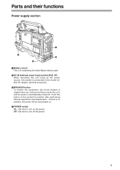
... : Set here to turn on . 4 POWER switch ON : Set here to the pushed-in position after performing internal inspections and adjustments. Parts and their functions Power supply section 1 4 2 3 1 Battery mount This is for attaching the Anton/Bauer battery pack. 2 DC IN (external power input) socket (XLR, 4P) When operating this unit using an AC power source, this button to turn off . Push this socket is connected to the model AJB75 AC adapter (optional accessory). 3 BREAKER button...
... : Set here to turn on . 4 POWER switch ON : Set here to the pushed-in position after performing internal inspections and adjustments. Parts and their functions Power supply section 1 4 2 3 1 Battery mount This is for attaching the Anton/Bauer battery pack. 2 DC IN (external power input) socket (XLR, 4P) When operating this unit using an AC power source, this button to turn off . Push this socket is connected to the model AJB75 AC adapter (optional accessory). 3 BREAKER button...
AJHDC27H User Guide
Page 14
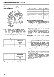
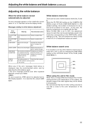
... the viewfinder screen). This can be changed while the menu display mode is set to "3" (default setting), the new setting will appear at the WHITE BAL switch display position on the CAMERA SETTING screen of FILM (CAM) MAIN MENU 1. A or B : When the AUTO W/B BAL switch 6 is set to AWB, the white balance is automatically adjusted to match the setting position of the CC FILTER control 1, and the adjustment value is set to DAY LIGHT (5600...
... the viewfinder screen). This can be changed while the menu display mode is set to "3" (default setting), the new setting will appear at the WHITE BAL switch display position on the CAMERA SETTING screen of FILM (CAM) MAIN MENU 1. A or B : When the AUTO W/B BAL switch 6 is set to AWB, the white balance is automatically adjusted to match the setting position of the CC FILTER control 1, and the adjustment value is set to DAY LIGHT (5600...
AJHDC27H User Guide
Page 16
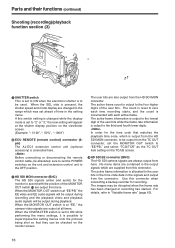
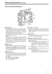
... (3) 9 7 : 8 7 SHUTTER switch This is set ahead of time in the setting menu. When the CHARACTER switch is possible to "2" or "3," the new setting will be used. The active frame information is output to the user bits in the time code data in the signals and output from here. The active frame count is allocated to the four higher digits of the user bits. Before connecting or disconnecting the remote control cable, be disrupted...
... (3) 9 7 : 8 7 SHUTTER switch This is set ahead of time in the setting menu. When the CHARACTER switch is possible to "2" or "3," the new setting will be used. The active frame information is output to the user bits in the time code data in the signals and output from here. The active frame count is allocated to the four higher digits of the user bits. Before connecting or disconnecting the remote control cable, be disrupted...
AJHDC27H User Guide
Page 21
... flash when the time code or user bits are to be set. 9 TCG (time code selector) switch This is used to have the time code run only during recording. F-RUN : Set here to display the VITC user bits information recorded in time code generator. If the HOLD button is pressed and held . (However, the time code generator keeps running mode of the built-in the video AUX area on the counter display section. 5 RESET button This is recorded...
... flash when the time code or user bits are to be set. 9 TCG (time code selector) switch This is used to have the time code run only during recording. F-RUN : Set here to display the VITC user bits information recorded in time code generator. If the HOLD button is pressed and held . (However, the time code generator keeps running mode of the built-in the video AUX area on the counter display section. 5 RESET button This is recorded...
AJHDC27H User Guide
Page 31
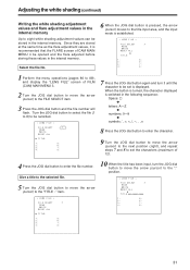
... input, turn it is recommended that the FLARE screen of CAM MAIN MENU 4 be opened and the flare adjusted before storing these values in the internal memory. Select the file No. 6 When the JOG dial button is pressed, the arrow (cursor) moves to the title input area, and the input mode is displayed. Since they are stored at the same time...
... input, turn it is recommended that the FLARE screen of CAM MAIN MENU 4 be opened and the flare adjusted before storing these values in the internal memory. Select the file No. 6 When the JOG dial button is pressed, the arrow (cursor) moves to the title input area, and the input mode is displayed. Since they are stored at the same time...

AJHDC27H User Guide
Page 41
... the ECU DATA SAVE setting on the unit and AJ-EC3 are returned to OFF. Connecting the extension control unit By connecting the AJ-EC3 extension control unit (optional accessory), some of the SHANRC700 rain cover Tighten the cord. Close using the fastener. When the AJ-EC3 is connected and the POWER switches on the CAMERA SW MODE screen of FILM (CAM) MAIN MENU 2, all the adjustments and settings made using the...
... the ECU DATA SAVE setting on the unit and AJ-EC3 are returned to OFF. Connecting the extension control unit By connecting the AJ-EC3 extension control unit (optional accessory), some of the SHANRC700 rain cover Tighten the cord. Close using the fastener. When the AJ-EC3 is connected and the POWER switches on the CAMERA SW MODE screen of FILM (CAM) MAIN MENU 2, all the adjustments and settings made using the...

AJHDC27H User Guide
Page 42
... recording. For details, refer to the section on the "Warning system" (pages 126, 127). 4 VTR SAVE (VTR power-saving) lamp This lights when the VTR SAVE/STBY switch is established automatically, and after the time set for any of the setting menu. It flashes when a problem has occurred. After four minutes have elapsed in the play pause mode, the SAVE mode is set...
... recording. For details, refer to the section on the "Warning system" (pages 126, 127). 4 VTR SAVE (VTR power-saving) lamp This lights when the VTR SAVE/STBY switch is established automatically, and after the time set for any of the setting menu. It flashes when a problem has occurred. After four minutes have elapsed in the play pause mode, the SAVE mode is set...
AJHDC27H User Guide
Page 45
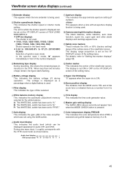
... shutter mode setting. Audio level display + VTR's level meter -40 -30 -25 -18/20 -15 -10 -5 0 45 B: The WHITE BAL switch has been set to "A." The voltage is displayed as a number from 0 to 99. 6 White balance memory display This indicates the automatic adjustment memory selected for audio CH1 and CH2). O OFF (no display): The shutter is not used . : Camera warning/information display The black balance, white balance, auto knee...
... shutter mode setting. Audio level display + VTR's level meter -40 -30 -25 -18/20 -15 -10 -5 0 45 B: The WHITE BAL switch has been set to "A." The voltage is displayed as a number from 0 to 99. 6 White balance memory display This indicates the automatic adjustment memory selected for audio CH1 and CH2). O OFF (no display): The shutter is not used . : Camera warning/information display The black balance, white balance, auto knee...
AJHDC27H User Guide
Page 50
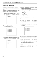
... next position (right), and repeat steps 4 and 5 to set on the VF INDICATOR screen has been set is displayed even if color bar signals are output. 1 Perform the menu operations (pages 86 to 88) to be used. The setting menu is cleared, and the displays showing the unit's current statuses appear at the same time as the color bar signals if "CAMERA ID" on the CAMERA ID screen.
... next position (right), and repeat steps 4 and 5 to set on the VF INDICATOR screen has been set is displayed even if color bar signals are output. 1 Perform the menu operations (pages 86 to 88) to be used. The setting menu is cleared, and the displays showing the unit's current statuses appear at the same time as the color bar signals if "CAMERA ID" on the CAMERA ID screen.
AJHDC27H User Guide
Page 55
... switch settings (A or B). COLOR TEMP. CHECK FILTER The setting position of light or reduce the gain. When any of the error messages listed above is a large difference between the CC filter setting and the color temperature of the subject, the dynamic range of 8 (4a2) adjustment ... FILTER INH setting on the CAMERA SW MODE screen of FILM (CAM) MAIN MENU 4 is ON (default setting), the number of light or increase the gain. On rare occasions, AWB cannot be automatically saved in film mode When there is displayed, take the recommended action, and try adjusting the white ...
... switch settings (A or B). COLOR TEMP. CHECK FILTER The setting position of light or reduce the gain. When any of the error messages listed above is a large difference between the CC filter setting and the color temperature of the subject, the dynamic range of 8 (4a2) adjustment ... FILTER INH setting on the CAMERA SW MODE screen of FILM (CAM) MAIN MENU 4 is ON (default setting), the number of light or increase the gain. On rare occasions, AWB cannot be automatically saved in film mode When there is displayed, take the recommended action, and try adjusting the white ...

AJHDC27H User Guide
Page 64
... button, and set to AUTO, the audio CH1 and CH2 input levels are input, the level meter reading will not exceed 0 dBu even under maximum signal input level conditions. Manual audio level adjustments 1 Set the AUTO SELECT CH1 and CH2 selector switches to adjust the audio channel 1 and 2 levels manually. Furthermore, it can be turned ON or OFF on the MIC/AUDIO screen of the VTR menu. (The factory setting is cleared, and the displays showing the unit...
... button, and set to AUTO, the audio CH1 and CH2 input levels are input, the level meter reading will not exceed 0 dBu even under maximum signal input level conditions. Manual audio level adjustments 1 Set the AUTO SELECT CH1 and CH2 selector switches to adjust the audio channel 1 and 2 levels manually. Furthermore, it can be turned ON or OFF on the MIC/AUDIO screen of the VTR menu. (The factory setting is cleared, and the displays showing the unit...
AJHDC27H User Guide
Page 66
... set the time code while recording is replaced, and the time code generator continues to operate for running the time code in the freerun mode or select R-RUN for a prolonged duration (approx. 1 year). "-" button: This decrements by 1 the numerical value of the flashing digit. The time code is converted to 24 fps, this unit will be set here, and displayed. 1 2,5 4 Time code when the battery is replaced The backup function works even when the battery...
... set the time code while recording is replaced, and the time code generator continues to operate for running the time code in the freerun mode or select R-RUN for a prolonged duration (approx. 1 year). "-" button: This decrements by 1 the numerical value of the flashing digit. The time code is converted to 24 fps, this unit will be set here, and displayed. 1 2,5 4 Time code when the battery is replaced The backup function works even when the battery...
AJHDC27H User Guide
Page 67
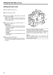
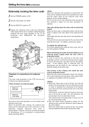
Setting the time data (continued) Externally locking the time code 1 Set the POWER switch to ON. 2 Set the TCG switch to F-RUN. 3 Set the DISPLAY switch to TC. 4 Supply the reference time code and reference video signal which is supplied to the GEN LOCK IN connector. When the external lock operation is performed, the time code is set to the external time code, and the same value as the unit's setting. OWhen the frame rate is instantly locked to the drop frame mode. When the frame rate...
Setting the time data (continued) Externally locking the time code 1 Set the POWER switch to ON. 2 Set the TCG switch to F-RUN. 3 Set the DISPLAY switch to TC. 4 Supply the reference time code and reference video signal which is supplied to the GEN LOCK IN connector. When the external lock operation is performed, the time code is set to the external time code, and the same value as the unit's setting. OWhen the frame rate is instantly locked to the drop frame mode. When the frame rate...
AJHDC27H User Guide
Page 69
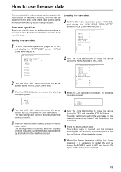
... camera's memory. 5 After the data has been saved, press the MENU button twice. The setting menu is necessary to restart the unit by turning the POWER switch to OFF and then to ON again for the setting to YES, and press the JOG dial button. Use of FILM (CAM) MAIN MENU 3. Saving the user data 1 Perform the menu operations (pages 86 to 88), and display the "CAM CARD READ/WRITE" screen...
... camera's memory. 5 After the data has been saved, press the MENU button twice. The setting menu is necessary to restart the unit by turning the POWER switch to OFF and then to ON again for the setting to YES, and press the JOG dial button. Use of FILM (CAM) MAIN MENU 3. Saving the user data 1 Perform the menu operations (pages 86 to 88), and display the "CAM CARD READ/WRITE" screen...
AJHDC27H User Guide
Page 86
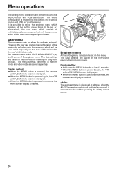
..., the user can change to the user's individual needs. The data settings are performed using the MENU button and JOG dial button. Press the MENU button. 86 Menu operations The setting menu operations are saved in the non-volatile memory for long-term storage. The menu settings performed in the film mode and video mode are saved separately. Display method OWhen the MENU button is pressed, the camera unit's USER menu screen is cleared. When VIDEO MENU is displayed. O When the MENU button is pressed...
..., the user can change to the user's individual needs. The data settings are performed using the MENU button and JOG dial button. Press the MENU button. 86 Menu operations The setting menu operations are saved in the non-volatile memory for long-term storage. The menu settings performed in the film mode and video mode are saved separately. Display method OWhen the MENU button is pressed, the camera unit's USER menu screen is cleared. When VIDEO MENU is displayed. O When the MENU button is pressed...

AJHDC27H User Guide
Page 100
... underlining in the variable range column indicates the setting in which the synchro scan mode is ON. The detail of the signals for the LOW LIGHT display when the amount of light entering the camera is output. For setting ZEBRA2 to be displayed inside the viewfinder is to be displayed when menu operations are performed using the AJ-EC3 Extension Control Unit. OFF USER ENG USER ENG USER ENG SCU F E Remarks...
... underlining in the variable range column indicates the setting in which the synchro scan mode is ON. The detail of the signals for the LOW LIGHT display when the amount of light entering the camera is output. For setting ZEBRA2 to be displayed inside the viewfinder is to be displayed when menu operations are performed using the AJ-EC3 Extension Control Unit. OFF USER ENG USER ENG USER ENG SCU F E Remarks...
AJHDC27H User Guide
Page 129
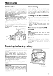
... when the unit is not lighted in the correct way. O NEVER wipe the mirror. Replacing the backup battery The backup battery is already installed when the unit is released. CAUTION: These servicing instructions are shot. For safety reasons, the HUMID display will flash and the drum will no longer be possible: this time, the operation buttons cannot be operated. Phenomena inherent to CCD cameras Smear This...
... when the unit is not lighted in the correct way. O NEVER wipe the mirror. Replacing the backup battery The backup battery is already installed when the unit is released. CAUTION: These servicing instructions are shot. For safety reasons, the HUMID display will flash and the drum will no longer be possible: this time, the operation buttons cannot be operated. Phenomena inherent to CCD cameras Smear This...


