

AJHDC27H User Guide
Page 1
Operating Instructions Camera-Recorder Model No. AJ- F0505T0 -F @ Printed in Japan ENGLISH VQT0R10 P Before operating this product, please read the instructions carefully and save this manual for future use.
Operating Instructions Camera-Recorder Model No. AJ- F0505T0 -F @ Printed in Japan ENGLISH VQT0R10 P Before operating this product, please read the instructions carefully and save this manual for future use.
AJHDC27H User Guide
Page 3
...status display section 19 Menu operation section 20 Time code related section 20 Power supply 22 Using the Anton/Bauer battery pack 22 Using the Panasonic battery pack 23 Using the Sony battery pack 24 Using the V-mount type battery pack 24 Using an AC power supply (When the ...the display items 46 Display modes and setting change messages . . .48 Switching the display mode 49 Setting the marker displays 49 Setting the camera ID 50 Screen displays 51 Remaining battery charge and audio channel level and remaining tape displays 51 Displays relating to errors and warnings 51 Displays...
...status display section 19 Menu operation section 20 Time code related section 20 Power supply 22 Using the Anton/Bauer battery pack 22 Using the Panasonic battery pack 23 Using the Sony battery pack 24 Using the V-mount type battery pack 24 Using an AC power supply (When the ...the display items 46 Display modes and setting change messages . . .48 Switching the display mode 49 Setting the marker displays 49 Setting the camera ID 50 Screen displays 51 Remaining battery charge and audio channel level and remaining tape displays 51 Displays relating to errors and warnings 51 Displays...

AJHDC27H User Guide
Page 4
...99 FILM (CAM) MAIN MENU 2 VF DISPLAY screen 100 VF MARKER screen 101 VF INDICATOR screen 101 CAMERA ID screen 102 SHUTTER SPEED screen 102 SHUTTER SELECT screen 103 !LED screen 104 CAMERA SW MODE screen 104 SUPER GAIN screen 106 FRAME MODE screen 106 FILM (CAM) MAIN MENU 3 ...126 Emergency eject 128 Error codes 128 Maintenance 129 Condensation 129 Head cleaning 129 Cleaning inside the viewfinder 129 Phenomena inherent to CCD cameras 129 Replacing the backup battery 129 Connectors and signals 130 Inspections prior to shooting 132 Preparation for inspection 132 Inspecting the...
...99 FILM (CAM) MAIN MENU 2 VF DISPLAY screen 100 VF MARKER screen 101 VF INDICATOR screen 101 CAMERA ID screen 102 SHUTTER SPEED screen 102 SHUTTER SELECT screen 103 !LED screen 104 CAMERA SW MODE screen 104 SUPER GAIN screen 106 FRAME MODE screen 106 FILM (CAM) MAIN MENU 3 ...126 Emergency eject 128 Error codes 128 Maintenance 129 Condensation 129 Head cleaning 129 Cleaning inside the viewfinder 129 Phenomena inherent to CCD cameras 129 Replacing the backup battery 129 Connectors and signals 130 Inspections prior to shooting 132 Preparation for inspection 132 Inspecting the...

AJHDC27H User Guide
Page 5
...compact and lightweight, has low power consumption, and excels in this led to the video mode using a conventional DVCPRO HD VTR is possible. Since digital signal processing is provided in a video camera. OHigh sensitivity: 2000 lx, F11, 24P mode, shutter speed set the unit to the capability of expressing ... made of many different presentation techniques. The shutter speed can be set as a result are all attributes which can be selected. What Panasonic did was to use to be set the unit to develop an exclusive gamma curve for reproducing film tones by setting the CINE GAMMA...
...compact and lightweight, has low power consumption, and excels in this led to the video mode using a conventional DVCPRO HD VTR is possible. Since digital signal processing is provided in a video camera. OHigh sensitivity: 2000 lx, F11, 24P mode, shutter speed set the unit to the capability of expressing ... made of many different presentation techniques. The shutter speed can be set as a result are all attributes which can be selected. What Panasonic did was to use to be set the unit to develop an exclusive gamma curve for reproducing film tones by setting the CINE GAMMA...

AJHDC27H User Guide
Page 6
... to the sensitivity equivalent to a film but also the various devices and equipment that are peripheral to the camera combine to the gain selector; Film user menu Panasonic does its best to cater to the USER1 and USER2 buttons: super iris, super gain, super black, ...GET (output luminance level measurement), frame rate switching. Digital signal processing Analog signals are featured as standard accessories The filter best suited to HD with the same ease afforded by incorporating as the AWB values. OGamma curves (switchable) for film producers. OThe following functions can be ...
... to the sensitivity equivalent to a film but also the various devices and equipment that are peripheral to the camera combine to the gain selector; Film user menu Panasonic does its best to cater to the USER1 and USER2 buttons: super iris, super gain, super black, ...GET (output luminance level measurement), frame rate switching. Digital signal processing Analog signals are featured as standard accessories The filter best suited to HD with the same ease afforded by incorporating as the AWB values. OGamma curves (switchable) for film producers. OThe following functions can be ...

AJHDC27H User Guide
Page 8
... adapter SHAN-TM700 Battery case AU-M402H BP-type battery Sony Battery case Sony Battery Battery mount connector (accessory) V-mount adapter plate Anton/Bauer Battery Camera-Recorder AJ-HDC27H IDX Battery Sony Battery Extension control unit AJ-EC3 AC adapter AJ-B75 Soft carrying case AJ-SC900 Hard carrying case AJ...
... adapter SHAN-TM700 Battery case AU-M402H BP-type battery Sony Battery case Sony Battery Battery mount connector (accessory) V-mount adapter plate Anton/Bauer Battery Camera-Recorder AJ-HDC27H IDX Battery Sony Battery Extension control unit AJ-EC3 AC adapter AJ-B75 Soft carrying case AJ-SC900 Hard carrying case AJ...

AJHDC27H User Guide
Page 13
...For details concerning the viewfinder, refer to "Adjusting the viewfinder" (page 34). 13 Its adjustment does not affect the output signals of the camera. 5 CONTRAST control This is used to adjust the brightness of the picture seen inside the viewfinder. Its adjustment does not affect the output ... ; OFF : The front tally lamp is underway, pictures can be viewed through the viewfinder in the viewfinder. HIGH: The brightness of the camera. ? LOW : The brightness of the front tally lamp is reduced. 4 PEAKING control This is used to adjust the front-back position of...
...For details concerning the viewfinder, refer to "Adjusting the viewfinder" (page 34). 13 Its adjustment does not affect the output signals of the camera. 5 CONTRAST control This is used to adjust the brightness of the picture seen inside the viewfinder. Its adjustment does not affect the output ... ; OFF : The front tally lamp is underway, pictures can be viewed through the viewfinder in the viewfinder. HIGH: The brightness of the camera. ? LOW : The brightness of the front tally lamp is reduced. 4 PEAKING control This is used to adjust the front-back position of...
AJHDC27H User Guide
Page 14
... automatically adjusted to the white balance that corresponds to this switch setting is changed while the menu display mode is set to OFF on the CAMERA SETTING screen of FILM (CAM) MAIN MENU 1. conversely, when the "+" switch is pressed, it is reduced; During personal computer monitor shooting, etc. This can be...
... automatically adjusted to the white balance that corresponds to this switch setting is changed while the menu display mode is set to OFF on the CAMERA SETTING screen of FILM (CAM) MAIN MENU 1. conversely, when the "+" switch is pressed, it is reduced; During personal computer monitor shooting, etc. This can be...

AJHDC27H User Guide
Page 15
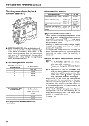
...is used to select the video signals which are to be recorded The pictures shot by the camera are output. The gain values corresponding to ON and the AUTO W/B BAL switch is pressed continuously for 8 seconds ...or more on the CAMERA SW MODE screen of FILM (CAM) MAIN MENU 2. Black shading is automatically corrected when SHD and ABB... MAIN MENU 4 are set to the L, M and H settings are specified by the camera are being automatically adjusted and the switch is pressed again to either the AWB side or to be output from...
...is used to select the video signals which are to be recorded The pictures shot by the camera are output. The gain values corresponding to ON and the AUTO W/B BAL switch is pressed continuously for 8 seconds ...or more on the CAMERA SW MODE screen of FILM (CAM) MAIN MENU 2. Black shading is automatically corrected when SHD and ABB... MAIN MENU 4 are set to the L, M and H settings are specified by the camera are being automatically adjusted and the switch is pressed again to either the AWB side or to be output from...
AJHDC27H User Guide
Page 16
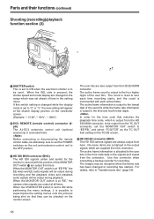
...", ": 50%", ": 180d") 8ECU REMOTE (remote control) connector (6pin) The AJ-EC3 extension control unit (optional accessory) is at "EE," the camera video signals are supplied from the HD SDI MON connector, to be checked on the unit and extension control unit to be used. Use this connector. Parts and their...and the playback video and playback audio signals will appear at the shutter display position on the TC/UB screen. : HD SDI EE connector (BNC) The HD SDI camera signals are contained in the setting menu. The user bits are output from the connector. If this switch setting is...
...", ": 50%", ": 180d") 8ECU REMOTE (remote control) connector (6pin) The AJ-EC3 extension control unit (optional accessory) is at "EE," the camera video signals are supplied from the HD SDI MON connector, to be checked on the unit and extension control unit to be used. Use this connector. Parts and their...and the playback video and playback audio signals will appear at the shutter display position on the TC/UB screen. : HD SDI EE connector (BNC) The HD SDI camera signals are contained in the setting menu. The user bits are output from the connector. If this switch setting is...

AJHDC27H User Guide
Page 18
This does not affect the output signals of the camera. @ USER 1 and USER 2 buttons A user setting can be reviewed (rewound and played back) at about twice the regular speed while the button is held down. ...'s lamp comes on during playback, the tape will cause the cassette to pause in the pause mode for two minutes, it is held down , the camera's setting mode is pressed during playback. The button's lamp comes on during playback, the unit is set to be cued (fast forwarded and played back...
This does not affect the output signals of the camera. @ USER 1 and USER 2 buttons A user setting can be reviewed (rewound and played back) at about twice the regular speed while the button is held down. ...'s lamp comes on during playback, the tape will cause the cassette to pause in the pause mode for two minutes, it is held down , the camera's setting mode is pressed during playback. The button's lamp comes on during playback, the unit is set to be cued (fast forwarded and played back...

AJHDC27H User Guide
Page 20
... input (TC IN) connector on Status display 1A B 0dB C Z73 Press the MENU button. ¢¢¢¢ FILM USER MENU ¢¢¢¢ Camera unit's user menu Press the MENU button. ¢¢¢¢ VTR USER MENU ¢¢¢¢ VTR unit's user menu Press the MENU... button. 1 32 1 GENLOCK IN connector (BNC) Supply the analog HD reference signal to this connector for writing/saving menu data. (See page 74) 2 MENU button When this dial button. When it is pressed once more...
... input (TC IN) connector on Status display 1A B 0dB C Z73 Press the MENU button. ¢¢¢¢ FILM USER MENU ¢¢¢¢ Camera unit's user menu Press the MENU button. ¢¢¢¢ VTR USER MENU ¢¢¢¢ VTR unit's user menu Press the MENU... button. 1 32 1 GENLOCK IN connector (BNC) Supply the analog HD reference signal to this connector for writing/saving menu data. (See page 74) 2 MENU button When this dial button. When it is pressed once more...

AJHDC27H User Guide
Page 23
... lifting the rubber caps forcibly. Select the battery type using the BATTERY SELECT menu item. Be sure to the camera-recorder. O Take special care not to the camera-recorder. Power supply (continued) Using the Panasonic battery pack 1 Remove the battery holder. 3 Connect the plug on the battery pack to the connector inside the...
... lifting the rubber caps forcibly. Select the battery type using the BATTERY SELECT menu item. Be sure to the camera-recorder. O Take special care not to the camera-recorder. Power supply (continued) Using the Panasonic battery pack 1 Remove the battery holder. 3 Connect the plug on the battery pack to the connector inside the...

AJHDC27H User Guide
Page 26
... the lever for securing the lens to the LENS socket. Lens auto iris operating speed adjustment 3. Lens flange back adjustment 2. OThe following lens adjustments and camera adjustments may be necessary depending on the lens mounted. 1. Attaching the lens 1 4 Raise the lever for securing the lens Mount cap LENS socket 2 Align the...
... the lever for securing the lens to the LENS socket. Lens auto iris operating speed adjustment 3. Lens flange back adjustment 2. OThe following lens adjustments and camera adjustments may be necessary depending on the lens mounted. 1. Attaching the lens 1 4 Raise the lever for securing the lens Mount cap LENS socket 2 Align the...

AJHDC27H User Guide
Page 27
...) ring. 7 Set the zoom ring to the wide-angle position, and turn the distance ring to adjust the focus. 2 Set the lens aperture to the camera. Approx. 3 meters 1 Attach the lens to manual and open the aperture. 3 Set the lighting in the telephoto and wide-angle modes during this may be...
...) ring. 7 Set the zoom ring to the wide-angle position, and turn the distance ring to adjust the focus. 2 Set the lens aperture to the camera. Approx. 3 meters 1 Attach the lens to manual and open the aperture. 3 Set the lighting in the telephoto and wide-angle modes during this may be...

AJHDC27H User Guide
Page 28
... move the arrow (cursor) to the item, and press the JOG dial button. 9 Turn the JOG dial button to move the arrow (cursor) to the camera. This is a phenomenon which is inherent to lenses and optical systems and is displayed, then turn the JOG dial button to move the arrow (cursor...
... move the arrow (cursor) to the item, and press the JOG dial button. 9 Turn the JOG dial button to move the arrow (cursor) to the camera. This is a phenomenon which is inherent to lenses and optical systems and is displayed, then turn the JOG dial button to move the arrow (cursor...

AJHDC27H User Guide
Page 35
Audio input preparation When attaching a microphone to the viewfinder (optional accessory) for use The microphone of the AJ-MC700P mic kit (optional accessory) can be recorded. AUDIO IN switches MIC IN jack 35 Locking screw 3 Connect the microphone's connecting cable to the viewfinder. 1 Open the mic holder. AJ-HVF27BP 4 Set the AUDIO IN switch or switches to "FRONT" in accordance with the audio channel or channels whose sound is to be attached to the MIC IN jack on the camera. Mic holder 2 Attach the microphone, and tighten the locking screw.
Audio input preparation When attaching a microphone to the viewfinder (optional accessory) for use The microphone of the AJ-MC700P mic kit (optional accessory) can be recorded. AUDIO IN switches MIC IN jack 35 Locking screw 3 Connect the microphone's connecting cable to the viewfinder. 1 Open the mic holder. AJ-HVF27BP 4 Set the AUDIO IN switch or switches to "FRONT" in accordance with the audio channel or channels whose sound is to be attached to the MIC IN jack on the camera. Mic holder 2 Attach the microphone, and tighten the locking screw.

AJHDC27H User Guide
Page 36
... IN switch or switches to "FRONT" in accordance with the audio channel or channels whose sound is to be recorded. 3 Attach the microphone to the camera recorder using the the 2 screws included. Locking screw 4 Loosen the locking lever and adjust the microphone angle then tighten the locking lever again. MIC IN... mic holder (optional accessory) 1 Remove the screws used to attach the mic holder. 5 Connect the microphone's connecting cable to the MIC IN jack on the camera. Locking lever 36 AUDIO IN switches
... IN switch or switches to "FRONT" in accordance with the audio channel or channels whose sound is to be recorded. 3 Attach the microphone to the camera recorder using the the 2 screws included. Locking screw 4 Loosen the locking lever and adjust the microphone angle then tighten the locking lever again. MIC IN... mic holder (optional accessory) 1 Remove the screws used to attach the mic holder. 5 Connect the microphone's connecting cable to the MIC IN jack on the camera. Locking lever 36 AUDIO IN switches

AJHDC27H User Guide
Page 37
... the phantom power supply system. AUDIO IN switches When the LINE/MIC/+48V selector switch is set to the AUDIO IN connector on the camera. Audio input preparation (continued) When connecting a microphone to the MIC IN jack When connecting a microphone to the AUDIO IN connector 1 ...Connect the microphone's connecting cable to the MIC IN jack on the camera. 1 Connect the microphone's connecting cable to "+48V," the phantom power supply system is supported. 37 AUDIO IN switches When extending the microphone...
... the phantom power supply system. AUDIO IN switches When the LINE/MIC/+48V selector switch is set to the AUDIO IN connector on the camera. Audio input preparation (continued) When connecting a microphone to the MIC IN jack When connecting a microphone to the AUDIO IN connector 1 ...Connect the microphone's connecting cable to the MIC IN jack on the camera. 1 Connect the microphone's connecting cable to "+48V," the phantom power supply system is supported. 37 AUDIO IN switches When extending the microphone...

AJHDC27H User Guide
Page 38
AUDIO IN switches LINE/MIC/+48V selector switch 38 AUDIO IN connectors 2 Set the AUDIO IN switch or switches for the channel or channels to which the audio component has been connected to "LINE." Audio input preparation (continued) When connecting audio components 1 Connect the AUDIO IN connectors on the rear panel to "REAR." 3 Set the LINE/MIC/+48V selector switch on the camera with the audio component using the XLR cable.
AUDIO IN switches LINE/MIC/+48V selector switch 38 AUDIO IN connectors 2 Set the AUDIO IN switch or switches for the channel or channels to which the audio component has been connected to "LINE." Audio input preparation (continued) When connecting audio components 1 Connect the AUDIO IN connectors on the rear panel to "REAR." 3 Set the LINE/MIC/+48V selector switch on the camera with the audio component using the XLR cable.


