
AJRC10G User Guide
Page 4
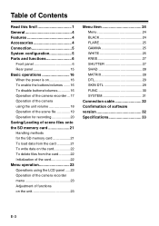
... 16 When the power is on 16 To enable the buttons/volumes .......16 To disable buttons/volumes 16 Operation of the camera recorder ...17 Operation of the camera using the unit volume 18 Operation of the scene file 19 Operation for recording 20 Saving/Loading of scene files onto the SD memory card... from the card 22 Initialization of the card 22 Menu operation 23 Operations using the LCD panel .....23 Operation of the camera recorder menu 23 Adjustment of functions on the unit 23 Menu item 24 Menu 24 BLACK 24 FLARE 25 GAMMA 25 WHITE 25 KNEE 27 SHUTTER 27 SHAD 28 MATRIX...
... 16 When the power is on 16 To enable the buttons/volumes .......16 To disable buttons/volumes 16 Operation of the camera recorder ...17 Operation of the camera using the unit volume 18 Operation of the scene file 19 Operation for recording 20 Saving/Loading of scene files onto the SD memory card... from the card 22 Initialization of the card 22 Menu operation 23 Operations using the LCD panel .....23 Operation of the camera recorder menu 23 Adjustment of functions on the unit 23 Menu item 24 Menu 24 BLACK 24 FLARE 25 GAMMA 25 WHITE 25 KNEE 27 SHUTTER 27 SHAD 28 MATRIX...
AJRC10G User Guide
Page 5
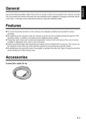
.... z Frequently used menus can be set by using a switch. Features z For some frequently functions on the camera unit, dedicated switches are output from the controller and is a remote control unit connected to the recorder mode, the camera recorder can be controlled directly through the VTR operation switch. z By switching to the scene file mode, it is also possible...
.... z Frequently used menus can be set by using a switch. Features z For some frequently functions on the camera unit, dedicated switches are output from the controller and is a remote control unit connected to the recorder mode, the camera recorder can be controlled directly through the VTR operation switch. z By switching to the scene file mode, it is also possible...
AJRC10G User Guide
Page 6
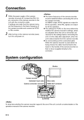
...forcefully pull the connected cable. z The frame frequency of the camera recorder must be switched before connecting the unit or to the state after adjustment, when the unit is applied directly to the connector. When the camera recorder is used while it is being moved, the cable must... turning on the camera recorder power, turn the unit power on the menu determine whether the camera recorder's settings, which are adjusted when the unit is turned off, connect the RCU 10pin connector of the camera recorder. Connection 1 While the power supply of the camera recorder is connected,...
...forcefully pull the connected cable. z The frame frequency of the camera recorder must be switched before connecting the unit or to the state after adjustment, when the unit is applied directly to the connector. When the camera recorder is used while it is being moved, the cable must... turning on the camera recorder power, turn the unit power on the menu determine whether the camera recorder's settings, which are adjusted when the unit is turned off, connect the RCU 10pin connector of the camera recorder. Connection 1 While the power supply of the camera recorder is connected,...
AJRC10G User Guide
Page 7
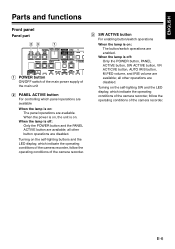
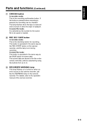
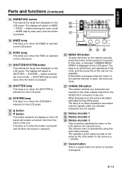
... buttons and the LED display, which indicate the operating conditions of the camera recorder, follow the operating conditions of the main unit !2" PANEL ACTIVE button For controlling which indicate the operating conditions of the camera recorder, follow the operating conditions of the camera recorder. !3" SW ACTIVE button For enabling button/switch operations When the lamp...
... buttons and the LED display, which indicate the operating conditions of the camera recorder, follow the operating conditions of the main unit !2" PANEL ACTIVE button For controlling which indicate the operating conditions of the camera recorder, follow the operating conditions of the camera recorder. !3" SW ACTIVE button For enabling button/switch operations When the lamp...
AJRC10G User Guide
Page 8
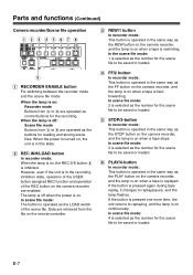
...is off when the power is on when a tape is on . However, even if the unit is on the camera recorder are operated as the number for the recording. When the power is turned on, the unit is in this state. !2" REC.INH/LOAD button In recorder mode: When the lamp is.... E-7 If the button is inhibited. If the button is pressed again during tape replay, it changes to replaying, and the lamp is on the remote controller. !3" REW/1 button In recorder mode: This button is operated in the recording inhibition state, operation of the USER button assigned REC function and operation ...
...is off when the power is on when a tape is on . However, even if the unit is on the camera recorder are operated as the number for the recording. When the power is turned on, the unit is in this state. !2" REC.INH/LOAD button In recorder mode: When the lamp is.... E-7 If the button is inhibited. If the button is pressed again during tape replay, it changes to replaying, and the lamp is on the remote controller. !3" REW/1 button In recorder mode: This button is operated in the recording inhibition state, operation of the USER button assigned REC function and operation ...
AJRC10G User Guide
Page 9
... when the tape is rewound and is turned on when the tape is turned on when an error occurs on the camera recorder, just like the WARNING lamp on the remote controller, which is selected by using the buttons from !3" to !7". !9" RECORDER WARNING lamp This lamp flashes or is replayed. ...For details, refer to be checked. In scene file mode: 5 is the start/stop button for recording. The current data are stored in the file on the camera recorder....
... when the tape is rewound and is turned on when the tape is turned on when an error occurs on the camera recorder, just like the WARNING lamp on the remote controller, which is selected by using the buttons from !3" to !7". !9" RECORDER WARNING lamp This lamp flashes or is replayed. ...For details, refer to be checked. In scene file mode: 5 is the start/stop button for recording. The current data are stored in the file on the camera recorder....

AJRC10G User Guide
Page 10
...Functions assigned to the USER2 button are selected in the menu of the camera recorder or the unit. !2" USER1 button This button has the same function as the USER2 switch on the camera recorder. When the power is turned on, the unit is indicated with A/b/C/d. For the ND filter display, the filter position...turning off the power. When the power is on only when the button is pressed. When the power is turned on, the unit is displayed depending on the camera recorder. E-9 Functions assigned to the USER MAIN button are selected in the state it is pressed. The state will switch to ...
...Functions assigned to the USER2 button are selected in the menu of the camera recorder or the unit. !2" USER1 button This button has the same function as the USER2 switch on the camera recorder. When the power is turned on, the unit is indicated with A/b/C/d. For the ND filter display, the filter position...turning off the power. When the power is on only when the button is pressed. When the power is turned on, the unit is displayed depending on the camera recorder. E-9 Functions assigned to the USER MAIN button are selected in the state it is pressed. The state will switch to ...
AJRC10G User Guide
Page 11
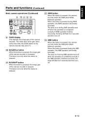
...during ABB operation and off . The lamp is on during AWB operation and off . !13" ABB button When this button is pressed, the camera recorder starts the AWB (Auto White Balance) operation. If the ABB operation finishes incorrectly, the lamp will flash for 5 seconds and then turn... off when the operation is pressed, the camera recorder starts the ABB (Auto Black Balance) operation. The lamp is on only when this button is pressed. !11" M.GAIN 4 button When ...
...during ABB operation and off . The lamp is on during AWB operation and off . !13" ABB button When this button is pressed, the camera recorder starts the AWB (Auto White Balance) operation. If the ABB operation finishes incorrectly, the lamp will flash for 5 seconds and then turn... off when the operation is pressed, the camera recorder starts the ABB (Auto Black Balance) operation. The lamp is on only when this button is pressed. !11" M.GAIN 4 button When ...

AJRC10G User Guide
Page 12
... function ON/OFF. Even if the DTL item in the menu of the camera recorder. Even if the HIGH COLOR is set to "OFF" in the menu of the camera recorder, it ON using this button is pressed. When the unit is pressed. The lamp is on ; E-11 otherwise, the lamp is on... menu on when the HIGH COLOR function is impossible to the camera recorder, this button is pressed. The lamp is on the unit. otherwise, the lamp is connected to turn on , the unit is ON; "A" and "B" of the camera recorder ON/OFF. When the unit is off . !15" DTL OFF button This button switches the...
... function ON/OFF. Even if the DTL item in the menu of the camera recorder. Even if the HIGH COLOR is set to "OFF" in the menu of the camera recorder, it ON using this button is pressed. When the unit is pressed. The lamp is on ; E-11 otherwise, the lamp is on... menu on when the HIGH COLOR function is impossible to the camera recorder, this button is pressed. The lamp is on the unit. otherwise, the lamp is connected to turn on , the unit is ON; "A" and "B" of the camera recorder ON/OFF. When the unit is off . !15" DTL OFF button This button switches the...
AJRC10G User Guide
Page 13
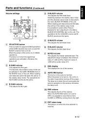
... adjustment in the camera; The operations for the B GAIN volume are the same. !3" B GAIN volume This adjusts the Bch gain. !4" R BLACK volume This adjusts the Rch black level. The lamp is on when the unit commands the auto iris operation in the Menu BLACK-VR-CONTROL item on the unit. otherwise, the ...lamp is off . !2" R GAIN volume This adjusts the Rch gain. When the power is turned on, the unit is in the state it inhibits operations. The ...
... adjustment in the camera; The operations for the B GAIN volume are the same. !3" B GAIN volume This adjusts the Bch gain. !4" R BLACK volume This adjusts the Rch black level. The lamp is on when the unit commands the auto iris operation in the Menu BLACK-VR-CONTROL item on the unit. otherwise, the ...lamp is off . !2" R GAIN volume This adjusts the Rch gain. When the power is turned on, the unit is in the state it inhibits operations. The ...
AJRC10G User Guide
Page 15
... on the LCD panel. The operation of the menu and the scene file on the unit are not loaded. !24" Rotary encoder 1 !25" Rotary encoder 2 !26" Rotary encoder 3 This is used for operating the menu on the camera (+, -, PUSH) !27" Vacant button This is assigned. E-14 If this button continuously for ... is a vacant button for 3 seconds. The lamp is on the camera recorder, press this button is off when characters are not available. When the power is on, the unit is in the state it is pressed when the menu of the unit. The display will switch to KNEE # FUNC # before entering the...
... on the LCD panel. The operation of the menu and the scene file on the unit are not loaded. !24" Rotary encoder 1 !25" Rotary encoder 2 !26" Rotary encoder 3 This is used for operating the menu on the camera (+, -, PUSH) !27" Vacant button This is assigned. E-14 If this button continuously for ... is a vacant button for 3 seconds. The lamp is on the camera recorder, press this button is off when characters are not available. When the power is on, the unit is in the state it is pressed when the menu of the unit. The display will switch to KNEE # FUNC # before entering the...

AJRC10G User Guide
Page 16
...signals. When the screws are removed. Parts and functions (Continued) Rear panel !6" !2" !1" VIDEO OUT CAM RCU CABLE FREQUENCY LEVEL 50m 10m !3" !4" !5" !1" Camera connection connector To connect the 10-pin camera control cable. 18 2 7 9 10 3 6 45 Pin No. 1 2 3 4 5 6 7 8 9 10 Signal CAM DATA (H) CAM DATA (C) CAM... CONT (H) CAM CONT (L) ECU_ON Video input GND (Video) Standby +12 V (IN) GND !6" Covering screw The unit can be used when the ...
...signals. When the screws are removed. Parts and functions (Continued) Rear panel !6" !2" !1" VIDEO OUT CAM RCU CABLE FREQUENCY LEVEL 50m 10m !3" !4" !5" !1" Camera connection connector To connect the 10-pin camera control cable. 18 2 7 9 10 3 6 45 Pin No. 1 2 3 4 5 6 7 8 9 10 Signal CAM DATA (H) CAM DATA (C) CAM... CONT (H) CAM CONT (L) ECU_ON Video input GND (Video) Standby +12 V (IN) GND !6" Covering screw The unit can be used when the ...
AJRC10G User Guide
Page 17
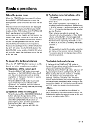
... intend to switch the displayed GAIN volume # BLACK volume # a numerical value for the PANEL ACTIVE button is turned off , operations using the volume controls is moved when inhibited, the volume level change will be reflected immediately after turning on the panel are enabled. If the button operations are enabled...the SW ACTIVE button is pressed and the lamp is possible for the GAIN and the BLACK to switch the display when the unit menu or the camera menu is operated. It is impossible to avoid changes in the volume position during the inhibition by setting the volume mode on ...
... intend to switch the displayed GAIN volume # BLACK volume # a numerical value for the PANEL ACTIVE button is turned off , operations using the volume controls is moved when inhibited, the volume level change will be reflected immediately after turning on the panel are enabled. If the button operations are enabled...the SW ACTIVE button is pressed and the lamp is possible for the GAIN and the BLACK to switch the display when the unit menu or the camera menu is operated. It is impossible to avoid changes in the volume position during the inhibition by setting the volume mode on ...

AJRC10G User Guide
Page 18
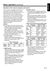
...display. The lamp is on when the unit is pressed. The lamp is on when the camera output outputs the color bar. 4) Operation of other buttons are on the camera recorder. The lamps for the other switches ... OFF button is on when the button is set and confirmed on the camera menu or the USER-SW item on the unit menu. 3) Operation of the ABB/AWB/BAR switch The ABB button and...display. However, if super gain is OFF. The lamp for 5 seconds. E-17 The state of the camera recorder filter is indicated with numerical values while the CC filter is displayed on . The ND filter is ...
...display. The lamp is on when the unit is pressed. The lamp is on when the camera output outputs the color bar. 4) Operation of other buttons are on the camera recorder. The lamps for the other switches ... OFF button is on when the button is set and confirmed on the camera menu or the USER-SW item on the unit menu. 3) Operation of the ABB/AWB/BAR switch The ABB button and...display. However, if super gain is OFF. The lamp for 5 seconds. E-17 The state of the camera recorder filter is indicated with numerical values while the CC filter is displayed on . The ND filter is ...
AJRC10G User Guide
Page 19
..., the lamp of the VR ACTIVE button turns off , and the volume operation is possible to 0 Retains Retains Retains When the BLACK-VR-CONTROL item in the unit menu changes, the lamp of the VR ACTIVE button is impossible to "PED", the flare value can be selected as the volume for the... the GAIN volume and the BLACK volume are operated in the volume set to 0. In the unit menu, it is on , the IRIS volume functions as follows. z A variable range for setting the target value of the camera recorder is disabled. In this case, if the PEDESTAL OFFSET of the auto iris. Volume...
..., the lamp of the VR ACTIVE button turns off , and the volume operation is possible to 0 Retains Retains Retains When the BLACK-VR-CONTROL item in the unit menu changes, the lamp of the VR ACTIVE button is impossible to "PED", the flare value can be selected as the volume for the... the GAIN volume and the BLACK volume are operated in the volume set to 0. In the unit menu, it is on , the IRIS volume functions as follows. z A variable range for setting the target value of the camera recorder is disabled. In this case, if the PEDESTAL OFFSET of the auto iris. Volume...

AJRC10G User Guide
Page 21
... While the REC INH button lamp is on the unit will be lost. Otherwise, data in the scene file, operate the unit while the VR ACTIVE button lamp is loaded from the camera recorder. 3 Execute RCU-FACTORY on the SYSTEM menu of the remote controller, load data from the scene file from the card ...and store them out from the specific unit and store on the camera recorder or not, by using the REC S/S button. However,...
... While the REC INH button lamp is on the unit will be lost. Otherwise, data in the scene file, operate the unit while the VR ACTIVE button lamp is loaded from the camera recorder. 3 Execute RCU-FACTORY on the SYSTEM menu of the remote controller, load data from the scene file from the card ...and store them out from the specific unit and store on the camera recorder or not, by using the REC S/S button. However,...
AJRC10G User Guide
Page 24
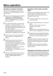
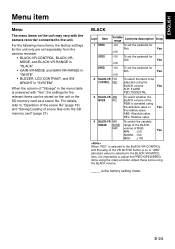
...the monitor. 2 Press the MENU ON button for the selected item is displayed on the main unit of the unit to 3 sub-items are not included in the unit menu. 1 Connect the VIDEO OUT connector of the camera recorder. When the lamp of the CHARA ON button is off, the menu is not displayed... is displayed on the LCD panel. 3 Move the layer on the LCD panel. 1 Press one of the unit is closed, "CAMERA MENU OPEN" is displayed. The menu of the camera recorder. E-23 For details such as frame frequency etc., cannot be adjusted using the rotary encoder. Significant items such as menu items...
...the monitor. 2 Press the MENU ON button for the selected item is displayed on the main unit of the unit to 3 sub-items are not included in the unit menu. 1 Connect the VIDEO OUT connector of the camera recorder. When the lamp of the CHARA ON button is off, the menu is not displayed... is displayed on the LCD panel. 3 Move the layer on the LCD panel. 1 Press one of the unit is closed, "CAMERA MENU OPEN" is displayed. The menu of the camera recorder. E-23 For details such as frame frequency etc., cannot be adjusted using the rotary encoder. Significant items such as menu items...
AJRC10G User Guide
Page 25
... the pedestal for : Rch Yes +100 GPED -100 To set the pedestal for : Gch Yes +100 BPED -100 To set separately from the camera recorder. Š BLACK-VR-CONTROL, BLACK-VRMODE, and BLACK-VR-RANGE in "BLACK" Š GAIN-VR-MODE and GAIN-VR-RANGE in "WHITE" Š BUZZER, LCD CONTRAST, ...rotary encoder. ABS MODE REL To select whether the BLACK volume of scene files onto the SD memory card" (page 21). is impossible to the unit. Adjust these items using the BLACK volume Yes FLR: FLARE PED: PEDESTAL 3 BLACK-VR- For the following menu items, the factory settings for the...
... the pedestal for : Rch Yes +100 GPED -100 To set the pedestal for : Gch Yes +100 BPED -100 To set separately from the camera recorder. Š BLACK-VR-CONTROL, BLACK-VRMODE, and BLACK-VR-RANGE in "BLACK" Š GAIN-VR-MODE and GAIN-VR-RANGE in "WHITE" Š BUZZER, LCD CONTRAST, ...rotary encoder. ABS MODE REL To select whether the BLACK volume of scene files onto the SD memory card" (page 21). is impossible to the unit. Adjust these items using the BLACK volume Yes FLR: FLARE PED: PEDESTAL 3 BLACK-VR- For the following menu items, the factory settings for the...

AJRC10G User Guide
Page 27
... 9 AWB-B MEM To set the position of the WHITE BAL switch and the color temperature in case of No Bch The step varies with the camera conditions. 8 AWB-A- E-26 TEMP-A 2300k : 8000k To set the position of the WHITE BAL switch and the assignment of Bch MEM: This assigns the Yes... 7 AWB-A MEM To set the position of the WHITE BAL switch and the color temperature in case of No Ach The step varies with the camera conditions. 10 AWB-B- TEMP-B 2300k : 8000k To set the position of the WHITE BAL switch and the assignment of Ach MEM: This assigns the Yes...
... 9 AWB-B MEM To set the position of the WHITE BAL switch and the color temperature in case of No Bch The step varies with the camera conditions. 8 AWB-A- E-26 TEMP-A 2300k : 8000k To set the position of the WHITE BAL switch and the assignment of Bch MEM: This assigns the Yes... 7 AWB-A MEM To set the position of the WHITE BAL switch and the color temperature in case of No Ach The step varies with the camera conditions. 10 AWB-B- TEMP-B 2300k : 8000k To set the position of the WHITE BAL switch and the assignment of Ach MEM: This assigns the Yes...
AJRC10G User Guide
Page 29
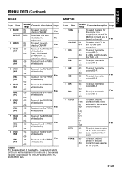
...the B-V-PARA : white shading +255 For the adjustment of the shading, the adjusted setting on the unit will be set on the RCDATA-SAVE item. E-28 ENGLISH Menu item (Continued) SHAD Layer Item...adjust the matrix : color of R-G +63 It will be retained in the main unit of the camera recorder regardless of the MATRIX ON and one to be adjusted in the 12-axis ...color correction Yes -63 To adjust the saturation : of the color +63 correction axis selected in case of the ON/OFF setting on the unit...
...the B-V-PARA : white shading +255 For the adjustment of the shading, the adjusted setting on the unit will be set on the RCDATA-SAVE item. E-28 ENGLISH Menu item (Continued) SHAD Layer Item...adjust the matrix : color of R-G +63 It will be retained in the main unit of the camera recorder regardless of the MATRIX ON and one to be adjusted in the 12-axis ...color correction Yes -63 To adjust the saturation : of the color +63 correction axis selected in case of the ON/OFF setting on the unit...