
AJSD965 User Guide
Page 2
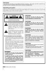
... OF FIRE OR SHOCK HAZARD, REFER CHANGE OF SWITCH SETTING INSIDE THE DECK TO QUALIFIED SERVICE PERSONNEL. indicates safety information. 2 NO USER SERVICEABLE PARTS INSIDE. CAUTION: TO REDUCE THE RISK OF FIRE OR SHOCK HAZARD AND ANNOYING INTERFERENCE, USE THE RECOMMENDED ACCESSORIES ONLY. CAUTION: Do not install or place this should be correctly wired to provide connection to the ground. The exclamation point...
... OF FIRE OR SHOCK HAZARD, REFER CHANGE OF SWITCH SETTING INSIDE THE DECK TO QUALIFIED SERVICE PERSONNEL. indicates safety information. 2 NO USER SERVICEABLE PARTS INSIDE. CAUTION: TO REDUCE THE RISK OF FIRE OR SHOCK HAZARD AND ANNOYING INTERFERENCE, USE THE RECOMMENDED ACCESSORIES ONLY. CAUTION: Do not install or place this should be correctly wired to provide connection to the ground. The exclamation point...
AJSD965 User Guide
Page 4
... (deck-to-deck 25 Switch settings and adjustments 25 Selecting the editing mode 26 Registering the edit points 26 Checking and previewing edit points 27 Modifying edit points 28 Executing and reviewing automatic editing . . . . . .29 Audio split editing 30 Variable memory editing 32 PF (Programmable Function) functions 33 Setup (initial settings 34 Setup menus 35 SYSTEM menu 38 USER menus 40
... (deck-to-deck 25 Switch settings and adjustments 25 Selecting the editing mode 26 Registering the edit points 26 Checking and previewing edit points 27 Modifying edit points 28 Executing and reviewing automatic editing . . . . . .29 Audio split editing 30 Variable memory editing 32 PF (Programmable Function) functions 33 Setup (initial settings 34 Setup menus 35 SYSTEM menu 38 USER menus 40
AJSD965 User Guide
Page 5
... Panasonic's original digital slow-motion technology makes it possible to attain clear pictures even during slow playback at 2 times the recording rate of the existing DVCPRO (25 Mbps) format. Compatibility with general consumer video equipment DV cassette tapes containing material shot with LCD monitor The LCD panel for the items registered can be changed directly using the rack mounting adapters (AJ-MA75P, optional accessory...
... Panasonic's original digital slow-motion technology makes it possible to attain clear pictures even during slow playback at 2 times the recording rate of the existing DVCPRO (25 Mbps) format. Compatibility with general consumer video equipment DV cassette tapes containing material shot with LCD monitor The LCD panel for the items registered can be changed directly using the rack mounting adapters (AJ-MA75P, optional accessory...
AJSD965 User Guide
Page 7
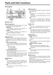
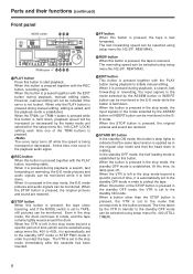
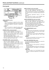
In this button to switch the mode when a device connected to the 9-pin REMOTE, RS-232C or PARALLEL connector is to be controlled by the time code generator incorporated inside the unit is output. OFF: The menus and other information are output. (The setup menu No.310 (CONFI EDIT) setting is necessary.) EE: The input signal selected by the INPUT SELECT button is used to enable recording. 2 Format display area The recording format and the format...
In this button to switch the mode when a device connected to the 9-pin REMOTE, RS-232C or PARALLEL connector is to be controlled by the time code generator incorporated inside the unit is output. OFF: The menus and other information are output. (The setup menu No.310 (CONFI EDIT) setting is necessary.) EE: The input signal selected by the INPUT SELECT button is used to enable recording. 2 Format display area The recording format and the format...
AJSD965 User Guide
Page 8
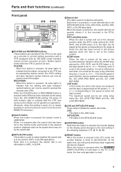
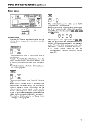
..., a search, fast forwarding or rewinding, the E-E mode pictures and audio signals can be monitored. When it is held down . The time taken by the frame mode unit selected for the setup menu No. 108 (CAP. REW MAX). > REW button When this button to start playback. In the standby OFF mode, the half loading mode is not locked. Parts and their functions (continued) Front panel MODE switch @ :; ON OFF POWER 2X REMOTE DVCPRO...
..., a search, fast forwarding or rewinding, the E-E mode pictures and audio signals can be monitored. When it is held down . The time taken by the frame mode unit selected for the setup menu No. 108 (CAP. REW MAX). > REW button When this button to start playback. In the standby OFF mode, the half loading mode is not locked. Parts and their functions (continued) Front panel MODE switch @ :; ON OFF POWER 2X REMOTE DVCPRO...
AJSD965 User Guide
Page 9
...+PLAYER) is set to -4.1a. When the power is turned on the display panel changes to the next setting in the clockwise direction, it is set to +4.1a. Similarly, when it is set to the center position, it is set to perform external control from the 9-pin REMOTE connector.) B Search button When this VTR). JOG mode: In this mode, the dial's click-stops are operated if the VTR is to be used...
...+PLAYER) is set to -4.1a. When the power is turned on the display panel changes to the next setting in the clockwise direction, it is set to +4.1a. Similarly, when it is set to the center position, it is set to perform external control from the 9-pin REMOTE connector.) B Search button When this VTR). JOG mode: In this mode, the dial's click-stops are operated if the VTR is to be used...
AJSD965 User Guide
Page 11
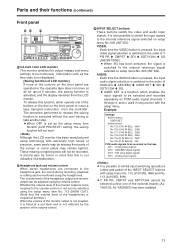
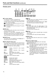
... recorded separately on the front panel or issue a tape transport instruction from the controller. R INPUT SELECT buttons These buttons switch the video and audio input signals. It is also possible to switch the input signals to the internal reference signal selected on the tape CH1 : Analog input signals CH2 : AES/EBU digital signals CH3 : SDI input digital signals CH4 : Analog input signals O It is not affected by the position of the volume control. Information such as the setup menu...
... recorded separately on the front panel or issue a tape transport instruction from the controller. R INPUT SELECT buttons These buttons switch the video and audio input signals. It is also possible to switch the input signals to the internal reference signal selected on the tape CH1 : Analog input signals CH2 : AES/EBU digital signals CH3 : SDI input digital signals CH4 : Analog input signals O It is not affected by the position of the volume control. Information such as the setup menu...
AJSD965 User Guide
Page 13
...) button This button is changed in tandem with the monitor output. It is set using the AUDIO VOL SEL (REC/PB) switch X. Z SET button When this position, the audio signals are exited, and the original status is set it is pressed again, the original display is selected using the setup menus is entered. The mixed signals to the MONITOR R connector are the deck's serial number, power-on time, drum rotation time, tape travel time, number...
...) button This button is changed in tandem with the monitor output. It is set using the AUDIO VOL SEL (REC/PB) switch X. Z SET button When this position, the audio signals are exited, and the original status is set it is pressed again, the original display is selected using the setup menus is entered. The mixed signals to the MONITOR R connector are the deck's serial number, power-on time, drum rotation time, tape travel time, number...
AJSD965 User Guide
Page 14
... operation mode. 14 LOCAL: Set to this position to adjust the video output signals using a device which has been connected to the 9-pin REMOTE, RS-232C or PARALLEL connector. The maximum adjustment range is ±30 degrees. When the ENC CONTROL switch \ is set to LOCAL and the SET UP switch is set to MANUAL, the video output level can be adjusted using the HUE control. The maximum adjustment range is ±3 dB. PRESET: The time code generator can be adjusted using setup menu...
... operation mode. 14 LOCAL: Set to this position to adjust the video output signals using a device which has been connected to the 9-pin REMOTE, RS-232C or PARALLEL connector. The maximum adjustment range is ±30 degrees. When the ENC CONTROL switch \ is set to LOCAL and the SET UP switch is set to MANUAL, the video output level can be adjusted using the HUE control. The maximum adjustment range is ±3 dB. PRESET: The time code generator can be adjusted using setup menu...
AJSD965 User Guide
Page 15
... (Programmable Function) mode. PF SHIFT SET + PF This combination is used to set the unit to set the time code or user bit value. TC PRESET SHIFT PLAYER + TC PRESET This combination is also displayed on the LCD monitor. (The setup menu screen is used to set the unit to the "Setup (initial settings)" section (page 34). Parts and their functions (continued) Front panel ON OFF POWER 2X REMOTE DVCPRO 50 DVCPRO DV SUPER...
... (Programmable Function) mode. PF SHIFT SET + PF This combination is used to set the unit to set the time code or user bit value. TC PRESET SHIFT PLAYER + TC PRESET This combination is also displayed on the LCD monitor. (The setup menu screen is used to set the unit to the "Setup (initial settings)" section (page 34). Parts and their functions (continued) Front panel ON OFF POWER 2X REMOTE DVCPRO 50 DVCPRO DV SUPER...
AJSD965 User Guide
Page 16
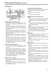
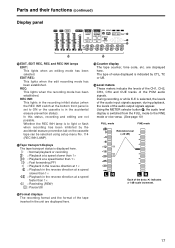
... : Analog audio signals : Digital audio signals : Recording audio signal selection : Serial digital audio signals : IEEE 1394 compressed digital signals (option) : Internal reference signals 5 U lamp This lamp lights when UMID information is being recorded on the input signal in E-E mode. Red : This lights when the error rate for the video and audio playback signals are both at acceptable levels. At all input signals except for the video or audio playback level has increased. Recording of the external synchronized signal (REF VIDEO) is indicated by setting setup menu item No...
... : Analog audio signals : Digital audio signals : Recording audio signal selection : Serial digital audio signals : IEEE 1394 compressed digital signals (option) : Internal reference signals 5 U lamp This lamp lights when UMID information is being recorded on the input signal in E-E mode. Red : This lights when the error rate for the video and audio playback signals are both at acceptable levels. At all input signals except for the video or audio playback level has increased. Recording of the external synchronized signal (REF VIDEO) is indicated by setting setup menu item No...
AJSD965 User Guide
Page 17
... audio input signals appear; during playback, the levels of the PCM audio signals. Using the METER selector button O, the audio level display is indicated by the accidental erasure prevention tab on the cassette tape can be selected using setup menu No. 114 (REC INH LAMP). ; Tape transport displays The tape transport status is selected, the levels of value displayed is switched from the FULL mode to light or flash...
... audio input signals appear; during playback, the levels of the PCM audio signals. Using the METER selector button O, the audio level display is indicated by the accidental erasure prevention tab on the cassette tape can be selected using setup menu No. 114 (REC INH LAMP). ; Tape transport displays The tape transport status is selected, the levels of value displayed is switched from the FULL mode to light or flash...
AJSD965 User Guide
Page 18
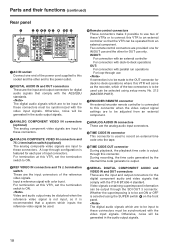
... is selected using setup menu No. 212 (MASTER PORT). 7 ENCODER REMOTE connector An external encoder remote controller is to be set the termination switch to this VTR will be generated in the audio output signals. 3ANALOG COMPONENT VIDEO IN connectors (optional) The analog component video signals are input to these connectors. 4 ANALOG COMPOSITE VIDEO IN connectors and 75 Ω termination switch (optional) The analog composite video signals are to be input to the power outlet. 2 DIGITAL AUDIO IN and...
... is selected using setup menu No. 212 (MASTER PORT). 7 ENCODER REMOTE connector An external encoder remote controller is to be set the termination switch to this VTR will be generated in the audio output signals. 3ANALOG COMPONENT VIDEO IN connectors (optional) The analog component video signals are input to these connectors. 4 ANALOG COMPOSITE VIDEO IN connectors and 75 Ω termination switch (optional) The analog composite video signals are to be input to the power outlet. 2 DIGITAL AUDIO IN and...
AJSD965 User Guide
Page 35
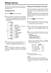
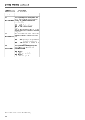
... 002 TAPE TIMER ±12h 003 REMAIN SEL OFF 004 SETUP NUMBER OFF 005 METER SELECT CUE 006 SYNCHRONIZE ON 007 SUPER ON 008 DISPLAY SEL T&STA 5 Press the SET button. Once the lock mode is to be set to the lock mode, a file cannot be made in user files 1 through 5, first select the user file and switch to No. 30 (MENU LOCK) for a user file. 4 Turn the search dial...
... 002 TAPE TIMER ±12h 003 REMAIN SEL OFF 004 SETUP NUMBER OFF 005 METER SELECT CUE 006 SYNCHRONIZE ON 007 SUPER ON 008 DISPLAY SEL T&STA 5 Press the SET button. Once the lock mode is to be set to the lock mode, a file cannot be made in user files 1 through 5, first select the user file and switch to No. 30 (MENU LOCK) for a user file. 4 Turn the search dial...
AJSD965 User Guide
Page 42
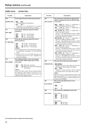
... the operator when the REF. However, if the MODE switch is set the play delay time in STOP, FF, REW and EJECT modes. CAP. VIDEO signal has not been connected. 0000 OFF : Warning is not given. 0001 ON : Warning is given by the INPUT SELECT button, internal operations are output with no delay. Setup menus (continued) USER menu No./Item Description 100 This selects the direct search dial operation.
... the operator when the REF. However, if the MODE switch is set the play delay time in STOP, FF, REW and EJECT modes. CAP. VIDEO signal has not been connected. 0000 OFF : Warning is not given. 0001 ON : Warning is given by the INPUT SELECT button, internal operations are output with no delay. Setup menus (continued) USER menu No./Item Description 100 This selects the direct search dial operation.
AJSD965 User Guide
Page 43
... and output. 0002 SOF&EJ : When the STANDBY OFF (HALF LOADING) or EJECT mode is established, the picture being played back at the time is selected as the setup menu item No. 105 (AUTO EE SEL) setting. This selects whether video input switching using the INPUT SELECT button is to be enabled or disabled. 0000 OFF : Audio input switching using the INPUT SELECT button is enabled. 0001 ON : Audio input switching using the INPUT SELECT button...
... and output. 0002 SOF&EJ : When the STANDBY OFF (HALF LOADING) or EJECT mode is established, the picture being played back at the time is selected as the setup menu item No. 105 (AUTO EE SEL) setting. This selects whether video input switching using the INPUT SELECT button is to be enabled or disabled. 0000 OFF : Audio input switching using the INPUT SELECT button is enabled. 0001 ON : Audio input switching using the INPUT SELECT button...
AJSD965 User Guide
Page 44
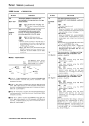
When the REC INH switch is set to remain lighted or be turned off in the cassette out status. 0000 MODE1 : The EJECT lamp remains lit. 0001 MODE2 : The EJECT lamp goes off. OFF : Operation is to the accidental erasure prevention status. 0000 LIGHT : The lamp lights up. 0001 FLASH : The lamp flashes. Setup menus (continued) USER menu No./Item Description 114 This...
When the REC INH switch is set to remain lighted or be turned off in the cassette out status. 0000 MODE1 : The EJECT lamp remains lit. 0001 MODE2 : The EJECT lamp goes off. OFF : Operation is to the accidental erasure prevention status. 0000 LIGHT : The lamp lights up. 0001 FLASH : The lamp flashes. Setup menus (continued) USER menu No./Item Description 114 This...
AJSD965 User Guide
Page 62
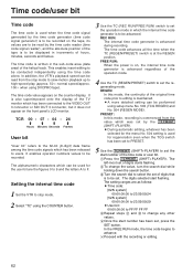
... RUN/FREE RUN) switch to users. This enables insert editing to be displayed in the sub-code area (data area) of the helical track. REC RUN: The internal time code generator is at the REGEN position. It enables operator numbers values to be set , press the SET button. O A more detailed setting can be read by the TC PRESET (SHIFT+PLAYER). The left-most set of digits starts flashing. 2To change...
... RUN/FREE RUN) switch to users. This enables insert editing to be displayed in the sub-code area (data area) of the helical track. REC RUN: The internal time code generator is at the REGEN position. It enables operator numbers values to be set , press the SET button. O A more detailed setting can be read by the TC PRESET (SHIFT+PLAYER). The left-most set of digits starts flashing. 2To change...
AJSD965 User Guide
Page 63
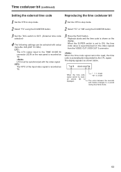
... CTL signal. Time code/user bit (continued) Setting the external time code Reproducing the time code/user bit 1 Set the VTR to stop mode. 1 Set the VTR to stop mode. 2 Select "TC" using the COUNTER button. 2 Select "TC" or "UB" using the COUNTER button. 3 Set the TCG switch to EXT. (External time code selection) 4 The following settings can be synchronized with setup menu No. 505 (EXT TC SEL). LTC: The LTC signal input to the TIME CODE IN connector (XLR) on the video signals...
... CTL signal. Time code/user bit (continued) Setting the external time code Reproducing the time code/user bit 1 Set the VTR to stop mode. 1 Set the VTR to stop mode. 2 Select "TC" using the COUNTER button. 2 Select "TC" or "UB" using the COUNTER button. 3 Set the TCG switch to EXT. (External time code selection) 4 The following settings can be synchronized with setup menu No. 505 (EXT TC SEL). LTC: The LTC signal input to the TIME CODE IN connector (XLR) on the video signals...
AJSD965 User Guide
Page 71
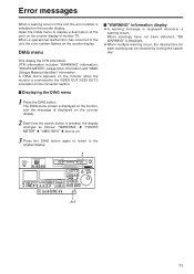
... this unit, the error number is pressed, the display changes as follows: "WARNING" 5 "HOURS METER" 5 "UMID INFO" 5 and so on the connector section. $ Displaying the DIAG menu 1 Press the DIAG button. DIAG menu $ "WARNING" information display OA warning message is displayed. This display the VTR information. The DIAG menu screen is displayed on the monitor, and the message is displayed on the counter display. 2 Each time the search button is indicated on the counter display or...
... this unit, the error number is pressed, the display changes as follows: "WARNING" 5 "HOURS METER" 5 "UMID INFO" 5 and so on the connector section. $ Displaying the DIAG menu 1 Press the DIAG button. DIAG menu $ "WARNING" information display OA warning message is displayed. This display the VTR information. The DIAG menu screen is displayed on the monitor, and the message is displayed on the counter display. 2 Each time the search button is indicated on the counter display or...


