
AJSPD850 User Guide
Page 6
Contents Introduction 7 Included accessories 7 Options 7 Features 8 Control reference guide 10 • Front Panel 10 • Display 15 • Rear Panel 16 Recording and playing 18 • Inserting P2 cards 18 • Removing P2 cards 18 • Protecting against a possible erasure 19 • P2 card access LEDs and P2 card status........19 Connections 20 Jog/Shuttle (Search dial 21 Working with clip thumbnails 22 Play List 34 • Using the play list 34 List of shortcuts 39 Setup (Initial settings 40 Setup menus 41 • SYSTEM menu 43 • USER menus 44
Contents Introduction 7 Included accessories 7 Options 7 Features 8 Control reference guide 10 • Front Panel 10 • Display 15 • Rear Panel 16 Recording and playing 18 • Inserting P2 cards 18 • Removing P2 cards 18 • Protecting against a possible erasure 19 • P2 card access LEDs and P2 card status........19 Connections 20 Jog/Shuttle (Search dial 21 Working with clip thumbnails 22 Play List 34 • Using the play list 34 List of shortcuts 39 Setup (Initial settings 40 Setup menus 41 • SYSTEM menu 43 • USER menus 44

AJSPD850 User Guide
Page 8
... install the USB driver onto your computer. • LAN You can connect to a network with a 100BASE-TX /10BASE-T. 4-channel, high-sound-quality digital audio The 4-channel PCM audio enables independent recording for an editing system with USB 2.0, you want them in time code generator (TCG) and time code reader (TCR). Multifunctional interface • Analog video input/output Both composite and component signal inputs/outputs are provided. • AES/EBU audio input/output Digital audio input and output connectors are provided. • Serial digital input/output...
... install the USB driver onto your computer. • LAN You can connect to a network with a 100BASE-TX /10BASE-T. 4-channel, high-sound-quality digital audio The 4-channel PCM audio enables independent recording for an editing system with USB 2.0, you want them in time code generator (TCG) and time code reader (TCR). Multifunctional interface • Analog video input/output Both composite and component signal inputs/outputs are provided. • AES/EBU audio input/output Digital audio input and output connectors are provided. • Serial digital input/output...
AJSPD850 User Guide
Page 10
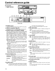
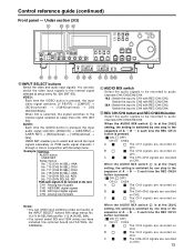
... 5 POWER switch Use when switching between ON and OFF of DV format. You will need to install the USB driver onto your computer. EE : The input signal selected by the INPUT SELECT button is on P2 cards with USB2.0, you can use this time, front panel controls of the files recorded on the display panel. Select at setup menu No. 201 (9P SEL) or No. 204 (RS232C SEL).→ LAN lights: You...
... 5 POWER switch Use when switching between ON and OFF of DV format. You will need to install the USB driver onto your computer. EE : The input signal selected by the INPUT SELECT button is on P2 cards with USB2.0, you can use this time, front panel controls of the files recorded on the display panel. Select at setup menu No. 201 (9P SEL) or No. 204 (RS232C SEL).→ LAN lights: You...
AJSPD850 User Guide
Page 11
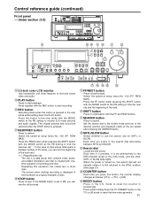
... Use thumbnails and other features to find and check video and audio. Press together with the MODE switch at the PB setting to find the next clip and the beginning of recording and stop. Press this button, the counter display changes as a typical example of P2 cards, you can monitor still pictures. STOP button Press to monitor E-E mode pictures and audio signals. Set the search dial to the shuttle mode and turn...
... Use thumbnails and other features to find and check video and audio. Press together with the MODE switch at the PB setting to find the next clip and the beginning of recording and stop. Press this button, the counter display changes as a typical example of P2 cards, you can monitor still pictures. STOP button Press to monitor E-E mode pictures and audio signals. Set the search dial to the shuttle mode and turn...
AJSPD850 User Guide
Page 12
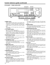
... monitor (when using the VIDEO OUT 3 or SDI OUT 3 connector (optional)). 12 Press again to exit the play list creation mode (the PLAYLIST and EVENT buttons light) press this button, the numbers of access to show the setup menus on and off or flashes depending on the memory card recorder's display panel. Under section (2/3) SLOT COUNTER MENU TC PRESET SELECT MENU RESET THUMBNAIL BAR MARKER SET SEARCH SHTL SLOW...
... monitor (when using the VIDEO OUT 3 or SDI OUT 3 connector (optional)). 12 Press again to exit the play list creation mode (the PLAYLIST and EVENT buttons light) press this button, the numbers of access to show the setup menus on and off or flashes depending on the memory card recorder's display panel. Under section (2/3) SLOT COUNTER MENU TC PRESET SELECT MENU RESET THUMBNAIL BAR MARKER SET SEARCH SHTL SLOW...
AJSPD850 User Guide
Page 13
... the setup menu. ENC CONTROL REMOTE VIDEO CHROMA LEVEL PRESET LEVEL PRESET LOCAL MANUAL MANUAL SET UP HUE BLK PRESET CHROMA PH PRESET TC REGEN REC RUN MANUAL MANUAL PRESET FREE RUN DIAG INPUT SELECT buttons Switch the video and audio input signals. B The CH2 signals are recorded on CH2. B The CH1+CH2 signals are recorded on PCM audio signal channels 1 through 4. B The CH4 signals are recorded on CH1. You can inhibit input switching (video and audio) of A → B → C each time...
... the setup menu. ENC CONTROL REMOTE VIDEO CHROMA LEVEL PRESET LEVEL PRESET LOCAL MANUAL MANUAL SET UP HUE BLK PRESET CHROMA PH PRESET TC REGEN REC RUN MANUAL MANUAL PRESET FREE RUN DIAG INPUT SELECT buttons Switch the video and audio input signals. B The CH2 signals are recorded on CH2. B The CH1+CH2 signals are recorded on PCM audio signal channels 1 through 4. B The CH4 signals are recorded on CH1. You can inhibit input switching (video and audio) of A → B → C each time...
AJSPD850 User Guide
Page 14
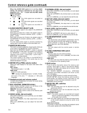
...). Headphone jack and volume control Connect stereo headphones to [PRESET], the video output level is pressed. ( ON; LOCAL : Encoder control is a unity value (0 °). When set to [PRESET], the hue is done on CH4. When set to monitor the sound during recording or playback. When set to [LOCAL], you can adjust the hue. When set to [MANUAL], you press the R button, the signals output to the MONITOR L connector change in 0.5 dB...
...). Headphone jack and volume control Connect stereo headphones to [PRESET], the video output level is pressed. ( ON; LOCAL : Encoder control is a unity value (0 °). When set to [PRESET], the hue is done on CH4. When set to monitor the sound during recording or playback. When set to [LOCAL], you can adjust the hue. When set to [MANUAL], you press the R button, the signals output to the MONITOR L connector change in 0.5 dB...
AJSPD850 User Guide
Page 15
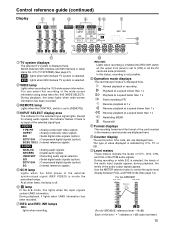
... recorded. Use the METER selector button to [REMOTE]. During playback, the lamp lights when wide-screen information has been recorded. are displayed here. In this lights when the input signals contain UMID information. Switch between FULL and FINE mode (See page 14). Except for the selected input signal lights. REC INH: Lights when recording is inhibited (the REC INH switch on the upper front panel is selected, the levels of the PCM audio signals...
... recorded. Use the METER selector button to [REMOTE]. During playback, the lamp lights when wide-screen information has been recorded. are displayed here. In this lights when the input signals contain UMID information. Switch between FULL and FINE mode (See page 14). Except for the selected input signal lights. REC INH: Lights when recording is inhibited (the REC INH switch on the upper front panel is selected, the levels of the PCM audio signals...
AJSPD850 User Guide
Page 16
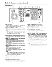
... analog audio input connectors. Video signals containing superimposed information can be generated in the memory card recorder enables input/output of digital component audio/video signals conforming to the power outlet. TIME CODE IN connector Use to an external controller. otherwise noise will be output through configuration is not input, so use the SUPER switch on the front panel. Remote control connectors Connect the memory card recorder to record an external time code onto the cards. Input a reference signal with the AES/EBU standards. Control reference guide (continued...
... analog audio input connectors. Video signals containing superimposed information can be generated in the memory card recorder enables input/output of digital component audio/video signals conforming to the power outlet. TIME CODE IN connector Use to an external controller. otherwise noise will be output through configuration is not input, so use the SUPER switch on the front panel. Remote control connectors Connect the memory card recorder to record an external time code onto the cards. Input a reference signal with the AES/EBU standards. Control reference guide (continued...

AJSPD850 User Guide
Page 20
... recorded images and playback images but not in the EE output. Perform the settings for the USB cable. 2. The menu item settings related to a PC. 20 Connect the USB cable to the PC, install the P2 software from the accessory CD-ROM into the PC. Use a cable that a system which inputs the reference video signal be disturbed when the reference video signal is not input, so it is recommended that supports USB2.0 (one deck...
... recorded images and playback images but not in the EE output. Perform the settings for the USB cable. 2. The menu item settings related to a PC. 20 Connect the USB cable to the PC, install the P2 software from the accessory CD-ROM into the PC. Use a cable that a system which inputs the reference video signal be disturbed when the reference video signal is not input, so it is recommended that supports USB2.0 (one deck...
AJSPD850 User Guide
Page 23
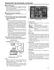
... display settings" on page 25. Clip numbers for clips with different recording formats or other clips that cannot be performed on the thumbnail screen to change the pointer to the normal display. It shows the time code at the start of a clip recording, or the user's bit at the start of thumbnails displayed on the display settings. Working with clip thumbnails (continued) Thumbnail screen Press the THUMBNAIL button to...
... display settings" on page 25. Clip numbers for clips with different recording formats or other clips that cannot be performed on the thumbnail screen to change the pointer to the normal display. It shows the time code at the start of a clip recording, or the user's bit at the start of thumbnails displayed on the display settings. Working with clip thumbnails (continued) Thumbnail screen Press the THUMBNAIL button to...
AJSPD850 User Guide
Page 24
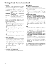
... repaired, so they were recorded. THUMBNAIL :This menu is displayed for performing clip operations, switching/setting the thumbnail display, etc. P Indicator for clips with proxy This marker is used to return the pointer to switch the thumbnail display or set the display method. The thumbnail screen is not necessary to select a clip (so that have different formats, etc. Notes: •Clips with clip numbers displayed in red...
... repaired, so they were recorded. THUMBNAIL :This menu is displayed for performing clip operations, switching/setting the thumbnail display, etc. P Indicator for clips with proxy This marker is used to return the pointer to switch the thumbnail display or set the display method. The thumbnail screen is not necessary to select a clip (so that have different formats, etc. Notes: •Clips with clip numbers displayed in red...

AJSPD850 User Guide
Page 30
... set from the menu bar: [OPERATION] →[DEVICE SETUP] → [NETWORK] →[MANUAL]. If the P2 card containing the clip is write-protected, a mark is also displayed in the DVD, cannot be used when a P2 card with clip thumbnails (continued) Network settings Perform the network settings. (1) Press the THUMBNAIL button. For [LOCALHOST NAME]: Alphanumerics and "-" can be a value which does not exist on the network connected. Clip number Thumbnail Clip information...
... set from the menu bar: [OPERATION] →[DEVICE SETUP] → [NETWORK] →[MANUAL]. If the P2 card containing the clip is write-protected, a mark is also displayed in the DVD, cannot be used when a P2 card with clip thumbnails (continued) Network settings Perform the network settings. (1) Press the THUMBNAIL button. For [LOCALHOST NAME]: Alphanumerics and "-" can be a value which does not exist on the network connected. Clip number Thumbnail Clip information...
AJSPD850 User Guide
Page 40
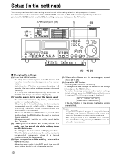
ENC CONTROL REMOTE VIDEO CHROMA LEVEL PRESET LEVEL PRESET LOCAL MANUAL MANUAL SET UP HUE BLK PRESET CHROMA PH PRESET TC REGEN REC RUN MANUAL MANUAL PRESET FREE RUN DIAG Changing the settings (1) Press the MENU button The setup menu screen appears on the TV monitor, and the setup menu item number appears on the rear panel and the SUPER switch is set to the factory settings (initial settings), press the RESET button while the menu is displayed. conversely...
ENC CONTROL REMOTE VIDEO CHROMA LEVEL PRESET LEVEL PRESET LOCAL MANUAL MANUAL SET UP HUE BLK PRESET CHROMA PH PRESET TC REGEN REC RUN MANUAL MANUAL PRESET FREE RUN DIAG Changing the settings (1) Press the MENU button The setup menu screen appears on the TV monitor, and the setup menu item number appears on the rear panel and the SUPER switch is set to the factory settings (initial settings), press the RESET button while the menu is displayed. conversely...
AJSPD850 User Guide
Page 43
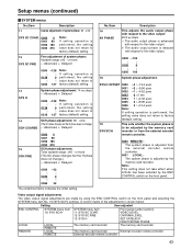
.../BLACK HUE/CHROMA PHASE LOCAL REMOTE LOCAL REMOTE LOCAL REMOTE The memory card recorder The memory card recorder The memory card recorder External encoder remote controller External encoder remote controller 43 Note: This setting does not take effect when LOCAL has been selected by using the ENC CONTROL switch on the front panel. No./Item 16 AV PHASE Description This adjusts the audio output phase with respect to the video output: 20.8 µs steps -: The audio output...
.../BLACK HUE/CHROMA PHASE LOCAL REMOTE LOCAL REMOTE LOCAL REMOTE The memory card recorder The memory card recorder The memory card recorder External encoder remote controller External encoder remote controller 43 Note: This setting does not take effect when LOCAL has been selected by using the ENC CONTROL switch on the front panel. No./Item 16 AV PHASE Description This adjusts the audio output phase with respect to the video output: 20.8 µs steps -: The audio output...

AJSPD850 User Guide
Page 48
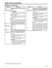
... of the MODE switch setting. 0001 STOP : EE status is established in STOP mode. PB: The picture becomes black and the sound is muted. 0004 GRAY : EE status is established in STOP mode. Setup menus (continued) USER menu No./Item Description 100 SEARCH ENA This selects the direct search dial operation. 0000 DIAL : For direct search dial operations. 0001 KEY : Operation is not transferred to the search mode unless the search button is pressed...
... of the MODE switch setting. 0001 STOP : EE status is established in STOP mode. PB: The picture becomes black and the sound is muted. 0004 GRAY : EE status is established in STOP mode. Setup menus (continued) USER menu No./Item Description 100 SEARCH ENA This selects the direct search dial operation. 0000 DIAL : For direct search dial operations. 0001 KEY : Operation is not transferred to the search mode unless the search button is pressed...
AJSPD850 User Guide
Page 49
... video input signals or when INT SG has been selected for video or audio, internal operations are output with a delay equivalent to the length of internal signal processing. 0001 THRU : Signals are output directly, without internal processing, and so are forcibly set to a recording mode is disabled. 0002 REC : Video input switching using the INPUT SELECT button after the memory card recorder has been transferred to NORMAL. 107 PLAY DELAY This set the setup menu...
... video input signals or when INT SG has been selected for video or audio, internal operations are output with a delay equivalent to the length of internal signal processing. 0001 THRU : Signals are output directly, without internal processing, and so are forcibly set to a recording mode is disabled. 0002 REC : Video input switching using the INPUT SELECT button after the memory card recorder has been transferred to NORMAL. 107 PLAY DELAY This set the setup menu...
AJSPD850 User Guide
Page 57
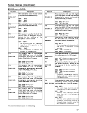
... display mode. 754 This selects the input audio channel switching mode using the REC AMIX SEL INH CH1/CH3 and REC CH2/CH4 buttons. 0000 OFF : The audio input channels can be switched using the REC CH buttons. 0001 ON : Switching of the audio input channels using the REC CH buttons is prohibited. 0002 REC : After the unit's operation has been transferred to recording, switching of the audio input channels using the REC CH buttons is linked to the setting of the volume control...
... display mode. 754 This selects the input audio channel switching mode using the REC AMIX SEL INH CH1/CH3 and REC CH2/CH4 buttons. 0000 OFF : The audio input channels can be switched using the REC CH buttons. 0001 ON : Switching of the audio input channels using the REC CH buttons is prohibited. 0002 REC : After the unit's operation has been transferred to recording, switching of the audio input channels using the REC CH buttons is linked to the setting of the volume control...
AJSPD850 User Guide
Page 63
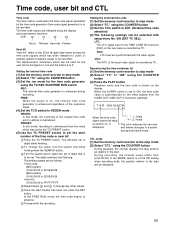
... with setup menu No. 505 (EXT TC SEL) LTC: The LTC signal input to the TIME CODE IN connector (XLR) on the video signals from [0:00:00:00]. PRESET: In this mode, the continuity of the time code or user bit Press the TC PRESET button. In the FREE RUN mode, the time code begins to a period during recording. To change any other values. Setting the external time code (1) Set the memory card recorder to the start number of...
... with setup menu No. 505 (EXT TC SEL) LTC: The LTC signal input to the TIME CODE IN connector (XLR) on the video signals from [0:00:00:00]. PRESET: In this mode, the continuity of the time code or user bit Press the TC PRESET button. In the FREE RUN mode, the time code begins to a period during recording. To change any other values. Setting the external time code (1) Set the memory card recorder to the start number of...
AJSPD850 User Guide
Page 74
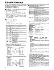
... PC.) Transmitted data 3 TXD (Data is received from PC.) Clear to send 4 CTS (Shorted with pin 5.) Request to send 5 RTS (Shorted with pin 4.) Data terminal ready 6 DTR (No processing) Signal ground 7 SG (Signal ground) Data set ready 20 DSR (+ voltage output after communication enable status) • Example of connection with controller (PC) (Using crossover cable with D-SUB 25-pin connectors) PC side (D-SUB 25-pin connector) deck side FG 1 TXD...
... PC.) Transmitted data 3 TXD (Data is received from PC.) Clear to send 4 CTS (Shorted with pin 5.) Request to send 5 RTS (Shorted with pin 4.) Data terminal ready 6 DTR (No processing) Signal ground 7 SG (Signal ground) Data set ready 20 DSR (+ voltage output after communication enable status) • Example of connection with controller (PC) (Using crossover cable with D-SUB 25-pin connectors) PC side (D-SUB 25-pin connector) deck side FG 1 TXD...


