
AJSPD850 User Guide
Page 6
Contents Introduction 7 Included accessories 7 Options 7 Features 8 Control reference guide 10 • Front Panel 10 • Display 15 • Rear Panel 16 Recording and playing 18 • Inserting P2 cards 18 • Removing P2 cards 18 • Protecting against a possible erasure 19 • P2 card access LEDs and P2 card status........19 Connections 20 Jog/Shuttle (Search dial 21 Working with clip thumbnails 22 Play List 34 • Using the play list 34 List of shortcuts 39 Setup (Initial settings 40 Setup menus 41 • SYSTEM menu 43 • USER menus 44
Contents Introduction 7 Included accessories 7 Options 7 Features 8 Control reference guide 10 • Front Panel 10 • Display 15 • Rear Panel 16 Recording and playing 18 • Inserting P2 cards 18 • Removing P2 cards 18 • Protecting against a possible erasure 19 • P2 card access LEDs and P2 card status........19 Connections 20 Jog/Shuttle (Search dial 21 Working with clip thumbnails 22 Play List 34 • Using the play list 34 List of shortcuts 39 Setup (Initial settings 40 Setup menus 41 • SYSTEM menu 43 • USER menus 44

AJSPD850 User Guide
Page 8
... enable input/output interfacing of IEEE1394 digital signals. • RS232C remote A RS232C remote connector is provided. • USB 2.0 By connecting a personal computer with a 100BASE-TX /10BASE-T. 4-channel, high-sound-quality digital audio The 4-channel PCM audio enables independent recording for all four channels in the order you to adjust the video output level, chroma, setup, and hue (chroma phase). Rack mounting Use the optional rack adapter (AJ-MA75P) to attach this 4U-sized deck to install the USB driver...
... enable input/output interfacing of IEEE1394 digital signals. • RS232C remote A RS232C remote connector is provided. • USB 2.0 By connecting a personal computer with a 100BASE-TX /10BASE-T. 4-channel, high-sound-quality digital audio The 4-channel PCM audio enables independent recording for all four channels in the order you to adjust the video output level, chroma, setup, and hue (chroma phase). Rack mounting Use the optional rack adapter (AJ-MA75P) to attach this 4U-sized deck to install the USB driver...
AJSPD850 User Guide
Page 10
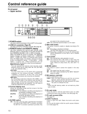
... input signal selected by the INPUT SELECT button is not output. When the REMOTE button is on the network through the 9-pin REMOTE, RS-232C, LAN, or USB 2.0 terminal. USB lights: By connecting a personal computer with a personal computer on (See page 18). 10 Format display area Shows the recording format and the format of the memory card recorder are output to enable recording. MODE switch This switch is used to enable or disable recording to P2 cards...
... input signal selected by the INPUT SELECT button is not output. When the REMOTE button is on the network through the 9-pin REMOTE, RS-232C, LAN, or USB 2.0 terminal. USB lights: By connecting a personal computer with a personal computer on (See page 18). 10 Format display area Shows the recording format and the format of the memory card recorder are output to enable recording. MODE switch This switch is used to enable or disable recording to P2 cards...
AJSPD850 User Guide
Page 11
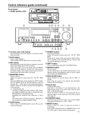
... data spans a multiple number of P2 cards, you press this button is first returned to [0:00:00:00]. STOP button Press to the desired position and playback starts at the PB setting to monitor E-E mode pictures and audio signals. The original pictures and sound are restored when the STOP button is created with the MODE switch at the PB setting to start playback. Set the search dial to the shuttle mode and turn...
... data spans a multiple number of P2 cards, you press this button is first returned to [0:00:00:00]. STOP button Press to the desired position and playback starts at the PB setting to monitor E-E mode pictures and audio signals. The original pictures and sound are restored when the STOP button is created with the MODE switch at the PB setting to start playback. Set the search dial to the shuttle mode and turn...
AJSPD850 User Guide
Page 12
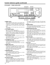
... mode (the PLAYLIST and EVENT buttons light) press this button first to stop status, use this to set the P2 card on the status of access to appear in order. OUT button Use when creating play list. Press again to exit the thumbnail screen. When setting the TC or UB value, press this button together with the ENTRY button to set of digits whose display is flashing is displayed, the MENU...
... mode (the PLAYLIST and EVENT buttons light) press this button first to stop status, use this to set the P2 card on the status of access to appear in order. OUT button Use when creating play list. Press again to exit the thumbnail screen. When setting the TC or UB value, press this button together with the ENTRY button to set of digits whose display is flashing is displayed, the MENU...
AJSPD850 User Guide
Page 13
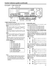
Control reference guide (continued) Front panel - AUDIO: Each time the AUDIO button is pressed, the input video signal switches: [Y PB PR] → [CMPST] → [SDI](optional) → [1394](optional) → [SG (SG/SG1/SG2)]. USER SET enables you have installed the optional board (AJ-YA755G, AJYAD850G). OFF) CH1/3 CH2/4 A The CH1 signals are recorded on CH1. B The CH2 signals are recorded on CH3. 13 When the AUDIO MIX switch is...
Control reference guide (continued) Front panel - AUDIO: Each time the AUDIO button is pressed, the input video signal switches: [Y PB PR] → [CMPST] → [SDI](optional) → [1394](optional) → [SG (SG/SG1/SG2)]. USER SET enables you have installed the optional board (AJ-YA755G, AJYAD850G). OFF) CH1/3 CH2/4 A The CH1 signals are recorded on CH1. B The CH2 signals are recorded on CH3. 13 When the AUDIO MIX switch is...
AJSPD850 User Guide
Page 14
.... FREE RUN: The time code runs when the memory card recorder is set to [REGEN], the time code runs constantly. WARNING shows warnings. VAR: The audio signals are to the MONITOR L/R connectors. When set to [MANUAL], you can be output to be adjusted using the audio level controls. Press again to return to the MONITOR L connector change in Setup Menu No. 503 (TCG REGEN). AUDIO MONITOR SELECT (L/R) Switch the audio signal to [LOCAL], you can adjust the video output...
.... FREE RUN: The time code runs when the memory card recorder is set to [REGEN], the time code runs constantly. WARNING shows warnings. VAR: The audio signals are to the MONITOR L/R connectors. When set to [MANUAL], you can be output to be adjusted using the audio level controls. Press again to return to the MONITOR L connector change in Setup Menu No. 503 (TCG REGEN). AUDIO MONITOR SELECT (L/R) Switch the audio signal to [LOCAL], you can adjust the video output...
AJSPD850 User Guide
Page 15
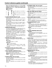
... reference signals AUDIO ANALOG AES/EBU USER SET SDI SDTI/1394 SG : Analog audio signals : Digital audio signals : Recording audio signal selection : Serial digital audio signals (option) : Compressed digital signals (option) : Internal reference signals SCH lamp Lights when the SCH phase of the external synchronized signal (REF VIDEO) is displayed here. During playback, it lights when UMID information has been recorded. Use the METER selector button to [ON] or all other times, the lamp is no input of the card inserted in setup menu No...
... reference signals AUDIO ANALOG AES/EBU USER SET SDI SDTI/1394 SG : Analog audio signals : Digital audio signals : Recording audio signal selection : Serial digital audio signals (option) : Compressed digital signals (option) : Internal reference signals SCH lamp Lights when the SCH phase of the external synchronized signal (REF VIDEO) is displayed here. During playback, it lights when UMID information has been recorded. Use the METER selector button to [ON] or all other times, the lamp is no input of the card inserted in setup menu No...
AJSPD850 User Guide
Page 16
... to adjust video output signal settings from an external component. 16 ANALOG AUDIO IN connectors These are input to these connectors. Video signals containing superimposed information can be synchronized with the video input signals; Note: Video and audio output may be generated in the memory card recorder enables input/output of the power cord supplied to this socket and the other end to the power outlet. DIGITAL AUDIO IN and OUT connectors These are the input and output connectors for each pair of input connectors. TIME CODE IN connector Use...
... to adjust video output signal settings from an external component. 16 ANALOG AUDIO IN connectors These are input to these connectors. Video signals containing superimposed information can be synchronized with the video input signals; Note: Video and audio output may be generated in the memory card recorder enables input/output of the power cord supplied to this socket and the other end to the power outlet. DIGITAL AUDIO IN and OUT connectors These are the input and output connectors for each pair of input connectors. TIME CODE IN connector Use...

AJSPD850 User Guide
Page 20
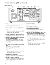
...) OPUTION IN OUT 1 2 SERVICE ONLY To video To audio monitor device monitor device Digital audio signal To video To audio monitor device monitor device Analog video signal (component) With analog video input board (optional) installed Notes: • Video and audio output may be used. • This unit does not come with a PC 1. Connect the USB cable to the installation manual. Connections Example of the memory card recorder and DVCPRO VTR Source machine: Set the CONTROL switch on the front panel...
...) OPUTION IN OUT 1 2 SERVICE ONLY To video To audio monitor device monitor device Digital audio signal To video To audio monitor device monitor device Analog video signal (component) With analog video input board (optional) installed Notes: • Video and audio output may be used. • This unit does not come with a PC 1. Connect the USB cable to the installation manual. Connections Example of the memory card recorder and DVCPRO VTR Source machine: Set the CONTROL switch on the front panel...
AJSPD850 User Guide
Page 23
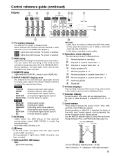
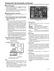
... displayed. By default, the time code at the pointer location. Press the MENU BAR button on thumbnails. ALL :All clips are not available during time code or user's bit settings when the TC REGEN/PRESET switch is set by the user are displayed. MARKED :Clips with shot marks are displayed. For details, see "Thumbnail display settings" on a specific P2 card are displayed. In addition, the slot number of clips recorded on the thumbnail screen...
... displayed. By default, the time code at the pointer location. Press the MENU BAR button on thumbnails. ALL :All clips are not available during time code or user's bit settings when the TC REGEN/PRESET switch is set by the user are displayed. MARKED :Clips with shot marks are displayed. For details, see "Thumbnail display settings" on a specific P2 card are displayed. In addition, the slot number of clips recorded on the thumbnail screen...
AJSPD850 User Guide
Page 24
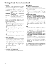
... red bad clip indicators cannot be repaired, so they were recorded. After the clip at the cursor location has been played, subsequent clips are inserted into the P2 card slots. P Indicator for clips with clip thumbnails (continued) Menu bar The menu bar contains menu items for performing clip operations, switching/setting the thumbnail display, etc. The thumbnail screen is displayed on the LCD. (2) Use the search...
... red bad clip indicators cannot be repaired, so they were recorded. After the clip at the cursor location has been played, subsequent clips are inserted into the P2 card slots. P Indicator for clips with clip thumbnails (continued) Menu bar The menu bar contains menu items for performing clip operations, switching/setting the thumbnail display, etc. The thumbnail screen is displayed on the LCD. (2) Use the search...

AJSPD850 User Guide
Page 30
... NAME] [USER] [FTP] [NEW USER] [USER NAME]/··· [DELETE USER] [CHANGE PASSWORD] [USER NAME]/··· [EXIT] [SAMBA] [SMB] [EXIT] [WORK GROUP] [EXIT] Notes: •Data cannot be recorded on the LCD. (2) Press the MENU BAR button, and select the following screen is displayed. Clip number Thumbnail Clip information Various indicators added to the operating instructions of the DVD drive unit when using the DVD drive unit. Then select...
... NAME] [USER] [FTP] [NEW USER] [USER NAME]/··· [DELETE USER] [CHANGE PASSWORD] [USER NAME]/··· [EXIT] [SAMBA] [SMB] [EXIT] [WORK GROUP] [EXIT] Notes: •Data cannot be recorded on the LCD. (2) Press the MENU BAR button, and select the following screen is displayed. Clip number Thumbnail Clip information Various indicators added to the operating instructions of the DVD drive unit when using the DVD drive unit. Then select...
AJSPD850 User Guide
Page 40
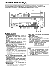
... RESET button while the menu is incremented; ENC CONTROL REMOTE VIDEO CHROMA LEVEL PRESET LEVEL PRESET LOCAL MANUAL MANUAL SET UP HUE BLK PRESET CHROMA PH PRESET TC REGEN REC RUN MANUAL MANUAL PRESET FREE RUN DIAG Changing the settings (1) Press the MENU button The setup menu screen appears on the TV monitor, and the setup menu item number appears on the TV monitor. When the dial is turned clockwise, the setting number is displayed. MENU INIT SET...
... RESET button while the menu is incremented; ENC CONTROL REMOTE VIDEO CHROMA LEVEL PRESET LEVEL PRESET LOCAL MANUAL MANUAL SET UP HUE BLK PRESET CHROMA PH PRESET TC REGEN REC RUN MANUAL MANUAL PRESET FREE RUN DIAG Changing the settings (1) Press the MENU button The setup menu screen appears on the TV monitor, and the setup menu item number appears on the TV monitor. When the dial is turned clockwise, the setting number is displayed. MENU INIT SET...
AJSPD850 User Guide
Page 43
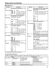
... is adjusted from the external encoder remote controller. 0001 LOCAL : The system phase is adjusted by using the ENC CONTROL switch on the front panel. Note: This setting does not take effect when LOCAL has been selected by the ENC CONTROL switch on the front panel and selecting the SYSTEM menu item No. 19 (SYS SC/H) settings. Video output signal adjustments The video output signal adjustments are made by the memory card recorder. A control...
... is adjusted from the external encoder remote controller. 0001 LOCAL : The system phase is adjusted by using the ENC CONTROL switch on the front panel. Note: This setting does not take effect when LOCAL has been selected by the ENC CONTROL switch on the front panel and selecting the SYSTEM menu item No. 19 (SYS SC/H) settings. Video output signal adjustments The video output signal adjustments are made by the memory card recorder. A control...

AJSPD850 User Guide
Page 48
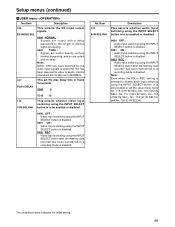
... is established at all times when the card is ejected, regardless of the MODE switch setting. 0002 BLACK : EE status is established in STOP mode. Setup menus (continued) USER menu No./Item Description 100 SEARCH ENA This selects the direct search dial operation. 0000 DIAL : For direct search dial operations. 0001 KEY : Operation is not transferred to ; Note: Video and audio output may be used. PB: The picture becomes gray and the sound is muted.
... is established at all times when the card is ejected, regardless of the MODE switch setting. 0002 BLACK : EE status is established in STOP mode. Setup menus (continued) USER menu No./Item Description 100 SEARCH ENA This selects the direct search dial operation. 0000 DIAL : For direct search dial operations. 0001 KEY : Operation is not transferred to ; Note: Video and audio output may be used. PB: The picture becomes gray and the sound is muted.
AJSPD850 User Guide
Page 49
... disabled. 0000 OFF : Audio input switching using the INPUT SELECT button is enabled. 0001 ON : Audio input switching using the INPUT SELECT button is disabled. 0002 REC : Audio input switching using the INPUT SELECT button after the memory card recorder has been transferred to the length of internal signal processing. 0001 THRU : Signals are output directly, without internal processing, and so are output with a delay equivalent to a recording mode is disabled. Setup menus (continued) USER menu No./Item Description 106...
... disabled. 0000 OFF : Audio input switching using the INPUT SELECT button is enabled. 0001 ON : Audio input switching using the INPUT SELECT button is disabled. 0002 REC : Audio input switching using the INPUT SELECT button after the memory card recorder has been transferred to the length of internal signal processing. 0001 THRU : Signals are output directly, without internal processing, and so are output with a delay equivalent to a recording mode is disabled. Setup menus (continued) USER menu No./Item Description 106...
AJSPD850 User Guide
Page 57
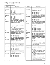
... FADE This selects whether to recording, switching of the audio input channels using the REC CH buttons is prohibited. 0002 REC : After the unit's operation has been transferred to superimpose the audio data onto the SDI output. 0000 OFF : Data is not superimposed. 0001 ON : Data is linked to the setting of the volume control. This selects whether the operation of the MONITOR SELECT button on the front panel is...
... FADE This selects whether to recording, switching of the audio input channels using the REC CH buttons is prohibited. 0002 REC : After the unit's operation has been transferred to superimpose the audio data onto the SDI output. 0000 OFF : Data is not superimposed. 0001 ON : Data is linked to the setting of the volume control. This selects whether the operation of the MONITOR SELECT button on the front panel is...
AJSPD850 User Guide
Page 63
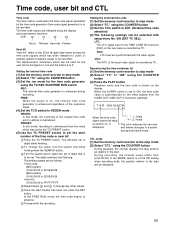
... original time code prior to the start. The digits selected start number has been set the start will be recorded. Once the start flashing. Proceed with the video signal. Setting the external time code (1) Set the memory card recorder to stop mode (2) Select "TC" using the COUNTER button (3) Set the run mode for the user bit are the figures 0 to 9 and the letters A to F. When the SUPER switch is shown on the video signals from the VIDEO OUT 3/SDI OUT 3 connector...
... original time code prior to the start. The digits selected start number has been set the start will be recorded. Once the start flashing. Proceed with the video signal. Setting the external time code (1) Set the memory card recorder to stop mode (2) Select "TC" using the COUNTER button (3) Set the run mode for the user bit are the figures 0 to 9 and the letters A to F. When the SUPER switch is shown on the video signals from the VIDEO OUT 3/SDI OUT 3 connector...
AJSPD850 User Guide
Page 74
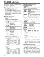
... PC.) Transmitted data 3 TXD (Data is received from PC.) Clear to send 4 CTS (Shorted with pin 5.) Request to send 5 RTS (Shorted with pin 4.) Data terminal ready 6 DTR (No processing) Signal ground 7 SG (Signal ground) Data set ready 20 DSR (+ voltage output after communication enable status) • Example of connection with controller (PC) (Using crossover cable with D-SUB 25-pin connectors) PC side (D-SUB 25-pin connector) deck side FG 1 TXD...
... PC.) Transmitted data 3 TXD (Data is received from PC.) Clear to send 4 CTS (Shorted with pin 5.) Request to send 5 RTS (Shorted with pin 4.) Data terminal ready 6 DTR (No processing) Signal ground 7 SG (Signal ground) Data set ready 20 DSR (+ voltage output after communication enable status) • Example of connection with controller (PC) (Using crossover cable with D-SUB 25-pin connectors) PC side (D-SUB 25-pin connector) deck side FG 1 TXD...


