
AKHBU931P User Guide
Page 1
Build-up Unit Model AK-HBU931P Before attempting to connect, operate or adjust this product, please read these instructions completely.
Build-up Unit Model AK-HBU931P Before attempting to connect, operate or adjust this product, please read these instructions completely.
AKHBU931P User Guide
Page 2
... safety information. 2 This equipment generates, uses, and can radiate radio frequency energy and, if not installed and used in accordance with the limits for a class A digital device, pursuant to correct the interference at his/her own expense. CAUTION: TO REDUCE THE RISK OF FIRE OR SHOCK HAZARD AND ANNOYING INTERFERENCE, USE ONLY THE RECOMMENDED ACCESSORIES . REFER SERVICING TO QUALIFIED SERVICE PERSONNEL...
... safety information. 2 This equipment generates, uses, and can radiate radio frequency energy and, if not installed and used in accordance with the limits for a class A digital device, pursuant to correct the interference at his/her own expense. CAUTION: TO REDUCE THE RISK OF FIRE OR SHOCK HAZARD AND ANNOYING INTERFERENCE, USE ONLY THE RECOMMENDED ACCESSORIES . REFER SERVICING TO QUALIFIED SERVICE PERSONNEL...
AKHBU931P User Guide
Page 3
... it enables a large lens to turn off the power before connecting or disconnecting the cables. ≥ Do not use carefully. 3 Contents Safety precautions 2 Overview 3 Operating precautions 3 Controls and their functions 4 Mounting methods 8 Connections 9 External dimension drawings 10 Specifications 11 Overview The model AK-HBU931P is a build-up unit's power from the monitor. ≥ Maintenance Disconnect the optical fiber cable plug, and wipe the unitr with the...
... it enables a large lens to turn off the power before connecting or disconnecting the cables. ≥ Do not use carefully. 3 Contents Safety precautions 2 Overview 3 Operating precautions 3 Controls and their functions 4 Mounting methods 8 Connections 9 External dimension drawings 10 Specifications 11 Overview The model AK-HBU931P is a build-up unit's power from the monitor. ≥ Maintenance Disconnect the optical fiber cable plug, and wipe the unitr with the...
AKHBU931P User Guide
Page 4
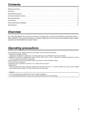
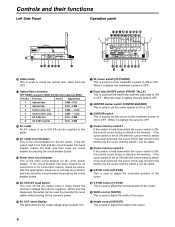
... CONTROL 7 CAMERA DATA 17 IRIS POSITION 8 CAMERA CONTROL 18 ZOOM POSITION 9 DC +12 V 19 FOCUS POSITION 10 POWER GND 20 IRIS AUTO/REMOTE 4 For details, refer to the operating instructions of the lens with the center groove, and attach. 2 Lens anchoring knob This is rotated clockwise to anchor the lens. 3 Lens connector Lens connector (57-20360 made by hooking it onto this guide. Signal Pin No. Signal...
... CONTROL 7 CAMERA DATA 17 IRIS POSITION 8 CAMERA CONTROL 18 ZOOM POSITION 9 DC +12 V 19 FOCUS POSITION 10 POWER GND 20 IRIS AUTO/REMOTE 4 For details, refer to the operating instructions of the lens with the center groove, and attach. 2 Lens anchoring knob This is rotated clockwise to anchor the lens. 3 Lens connector Lens connector (57-20360 made by hooking it onto this guide. Signal Pin No. Signal...
AKHBU931P User Guide
Page 5
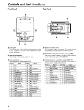
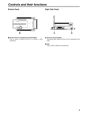
Controls and their functions Bottom Panel Right Side Panel 7 8 9 7 Screw hole for mounting tripod (3/8-16UNC) This is used to attach the unit to a tripod or other accessory. 8 Hook for securing cable The optical fiber cable from the CCU is fastened to this hook. 9 Clip This is used to attach the accessories. 5
Controls and their functions Bottom Panel Right Side Panel 7 8 9 7 Screw hole for mounting tripod (3/8-16UNC) This is used to attach the unit to a tripod or other accessory. 8 Hook for securing cable The optical fiber cable from the CCU is fastened to this hook. 9 Clip This is used to attach the accessories. 5
AKHBU931P User Guide
Page 6
Optical fiber connector OPT FIBER connector (EDW.3K.93C.CLC made by pressing the circuit breaker button. > Power main circuit breaker This is the main circuit-breaker for the unit's power supply. Function Polarity Signal flow 1 Optical fiber CAM#CCU 2 Optical fibe CCU#CAM 3 Control wire, hot + CAM!#CCU 4 Control wire, cold - AC OUTLET reset switch This cuts off the camera's power. 8 V-POSI control [V-POSI] This is used to adjust the vertical position...
Optical fiber connector OPT FIBER connector (EDW.3K.93C.CLC made by pressing the circuit breaker button. > Power main circuit breaker This is the main circuit-breaker for the unit's power supply. Function Polarity Signal flow 1 Optical fiber CAM#CCU 2 Optical fibe CCU#CAM 3 Control wire, hot + CAM!#CCU 4 Control wire, cold - AC OUTLET reset switch This cuts off the camera's power. 8 V-POSI control [V-POSI] This is used to adjust the vertical position...
AKHBU931P User Guide
Page 7
...-picture display position on the camera's menus. = ND filter selector switch [ND] This is used to set the picture-in P function ON/OFF switch This is lighted, the video signals of the items selected on the viewfinder screen. H MONITOR output selector switch [MONI SEL] This is the 4:3 marker ON/OFF switch. Controls and their functions ; 4:3 MARKER switch This is used to select the viewfinder's video output from the Y/C, R, G or B camera video signals. LOCAL switch...
...-picture display position on the camera's menus. = ND filter selector switch [ND] This is used to set the picture-in P function ON/OFF switch This is lighted, the video signals of the items selected on the viewfinder screen. H MONITOR output selector switch [MONI SEL] This is the 4:3 marker ON/OFF switch. Controls and their functions ; 4:3 MARKER switch This is used to select the viewfinder's video output from the Y/C, R, G or B camera video signals. LOCAL switch...
AKHBU931P User Guide
Page 8
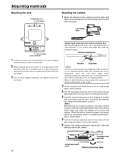
... to secure the camera. 6 Connect the camera connection optical fiber cable and interface cable to the front. 4 Insert the camera's bayonet mount by fitting it moves down. 5 Push the front/back slide lock lever of the lens and camera. When the knob is rotated clockwise, the camera moves up the lens lock knob. conversely, when it is horizontal. 2 Align the guide pin at this...
... to secure the camera. 6 Connect the camera connection optical fiber cable and interface cable to the front. 4 Insert the camera's bayonet mount by fitting it moves down. 5 Push the front/back slide lock lever of the lens and camera. When the knob is rotated clockwise, the camera moves up the lens lock knob. conversely, when it is horizontal. 2 Align the guide pin at this...
AKHBU931P User Guide
Page 9
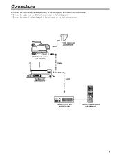
... OUTPUT CAM W.BAL B MID BAR A STBY SAVE HIGH TEST PRST PTT USER SEL SD CARD Multi-format camera (AK-HC931P) 8z LCD viewfinder (AK-HVF931P) Cable Build-up unit to the connector on the multi-format camera. DTL SD. CLOSE BAR TEST WHITE SD CARD AUTO BLACK SET UP CHARACTER RST ALARM OPT FAN CABLE 60Hz MODE FLARE BLK GAMMA AUTO KNEE WHITE MATRIX HD. Connections ≥ Connect...
... OUTPUT CAM W.BAL B MID BAR A STBY SAVE HIGH TEST PRST PTT USER SEL SD CARD Multi-format camera (AK-HC931P) 8z LCD viewfinder (AK-HVF931P) Cable Build-up unit to the connector on the multi-format camera. DTL SD. CLOSE BAR TEST WHITE SD CARD AUTO BLACK SET UP CHARACTER RST ALARM OPT FAN CABLE 60Hz MODE FLARE BLK GAMMA AUTO KNEE WHITE MATRIX HD. Connections ≥ Connect...
AKHBU931P User Guide
Page 10
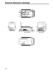
External dimension drawings 23-1/15z (585 mm) VF POWER FRONT TALLY CENTER MARKER CURSOR ON/OFF 1 2 RET A RET B USER SEL VF MARKER ON H-POSI V-POSI WIDTH HEIGHT VF DETAIL MONI SEL RG Y/G B EXT OFF 1 2 3 4 5 FILTER A B C D E MENU SELECT PIP LOCAL x0.8 ND CC 12-5/8z (320 mm) 13-5/16z (337.5 mm) 10
External dimension drawings 23-1/15z (585 mm) VF POWER FRONT TALLY CENTER MARKER CURSOR ON/OFF 1 2 RET A RET B USER SEL VF MARKER ON H-POSI V-POSI WIDTH HEIGHT VF DETAIL MONI SEL RG Y/G B EXT OFF 1 2 3 4 5 FILTER A B C D E MENU SELECT PIP LOCAL x0.8 ND CC 12-5/8z (320 mm) 13-5/16z (337.5 mm) 10
AKHBU931P User Guide
Page 11
Specifications Power supply: AC 220 V (supplied from CCU) Power consumption: 8 W (main unit only) 1indicates safety information. Switch functions: Adjustment functions: Operating temperature range: Storage temperature range: Operating ambient humidity: Dimensions: Weight: AC OUT reset, viewfinder power, front tally ON/OFF, CENTER marker, CURSOR, cursor memory 1, cursor memory 2, 4:3 MARKER, ND filter selection, LOCAL, CC filter selection, menu ON/OFF, menu JOG, RET A switch, RET B switch, user, VF DETAIL, MONITOR output selection, P in P function ON...
Specifications Power supply: AC 220 V (supplied from CCU) Power consumption: 8 W (main unit only) 1indicates safety information. Switch functions: Adjustment functions: Operating temperature range: Storage temperature range: Operating ambient humidity: Dimensions: Weight: AC OUT reset, viewfinder power, front tally ON/OFF, CENTER marker, CURSOR, cursor memory 1, cursor memory 2, 4:3 MARKER, ND filter selection, LOCAL, CC filter selection, menu ON/OFF, menu JOG, RET A switch, RET B switch, user, VF DETAIL, MONITOR output selection, P in P function ON...


