
AKHRP150G User Guide
Page 1
ESPAÑOL ITALIANO FRANÇAIS DEUTSCH ENGLISH Camera Controller AK-HRP150G Before attempting to connect, operate or adjust this product, please read these instructions completely. 中文
ESPAÑOL ITALIANO FRANÇAIS DEUTSCH ENGLISH Camera Controller AK-HRP150G Before attempting to connect, operate or adjust this product, please read these instructions completely. 中文
AKHRP150G User Guide
Page 6
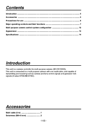
This unit is a camera controller for multi purpose camera (AK-HC1500G). Accessories Multi cable (5 m 1 Setscrews (M48 mm 2 - 5 (E) - Contents Introduction ...5 Accessories ...5 Precautions for use ...6 Major operating controls and their functions 7 Multi purpose camera control system configuration 12 Appearance ...13 Specifications ...14 Introduction This unit is connected to a multi purpose camera with one multi cable, and capable of transmitting and receiving various camera and lens control signals and generator lock signals (3-value SYNC/BB-SYNC).
This unit is a camera controller for multi purpose camera (AK-HC1500G). Accessories Multi cable (5 m 1 Setscrews (M48 mm 2 - 5 (E) - Contents Introduction ...5 Accessories ...5 Precautions for use ...6 Major operating controls and their functions 7 Multi purpose camera control system configuration 12 Appearance ...13 Specifications ...14 Introduction This unit is connected to a multi purpose camera with one multi cable, and capable of transmitting and receiving various camera and lens control signals and generator lock signals (3-value SYNC/BB-SYNC).
AKHRP150G User Guide
Page 8
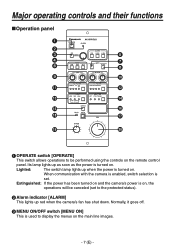
... enabled, switch selection is set to the protected status). Alarm indicator [ALARM] This lights up red when the camera's fan has shut down. Normally, it goes off. MENU ON/OFF switch [MENU ON] This is turned on . Its lamp lights up when the ...power is on the remote control panel. Extinguished: If the power has been turned on and the camera's power is turned on . Lighted: The switch lamp lights up as soon as the power is used to be performed using the controls on , the...
... enabled, switch selection is set to the protected status). Alarm indicator [ALARM] This lights up red when the camera's fan has shut down. Normally, it goes off. MENU ON/OFF switch [MENU ON] This is turned on . Its lamp lights up when the ...power is on the remote control panel. Extinguished: If the power has been turned on and the camera's power is turned on . Lighted: The switch lamp lights up as soon as the power is used to be performed using the controls on , the...
AKHRP150G User Guide
Page 9
...indicated by the lighting of the pedestal. Switch lamp flashes: If the black balance is not adjusted adequately upon completion of the switch lamp. Camera video, color bar display or test display is selected. Switch lamp lights: When the switch is pressed, the start of the automatic white ... and data entered. Scene file switches [SCENE PRE, USER1, USER2] These switches are used to call the scene file data registered by camera BAR switch lamp lighted: Color bar output TEST switch lamp lighted: Test signal output Auto white balance switch [AUTO WHITE] This switch is...
...indicated by the lighting of the pedestal. Switch lamp flashes: If the black balance is not adjusted adequately upon completion of the switch lamp. Camera video, color bar display or test display is selected. Switch lamp lights: When the switch is pressed, the start of the automatic white ... and data entered. Scene file switches [SCENE PRE, USER1, USER2] These switches are used to call the scene file data registered by camera BAR switch lamp lighted: Color bar output TEST switch lamp lighted: Test signal output Auto white balance switch [AUTO WHITE] This switch is...
AKHRP150G User Guide
Page 10
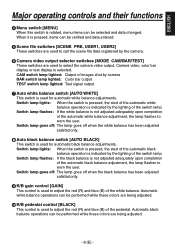
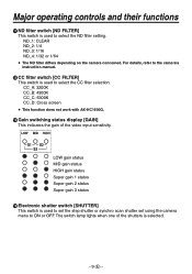
...status Super gain 3 status Electronic shutter switch [SHUTTER] This switch is used to select the CC filter selection. For details, refer to the camera's instruction manual. CC filter switch [CC FILTER] This switch is used to ON or OFF. Major operating controls and their functions ...switching status display [GAIN] This indicates the gain of the shutters is used to set the step shutter or synchro scan shutter set using the camera menu to select the ND filter setting. The switch lamp lights when one of the video input sensitivity. ND_1: CLEAR ND_2: 1/4 ND_3:...
...status Super gain 3 status Electronic shutter switch [SHUTTER] This switch is used to select the CC filter selection. For details, refer to the camera's instruction manual. CC filter switch [CC FILTER] This switch is used to ON or OFF. Major operating controls and their functions ...switching status display [GAIN] This indicates the gain of the shutters is used to set the step shutter or synchro scan shutter set using the camera menu to select the ND filter setting. The switch lamp lights when one of the video input sensitivity. ND_1: CLEAR ND_2: 1/4 ND_3:...
AKHRP150G User Guide
Page 12
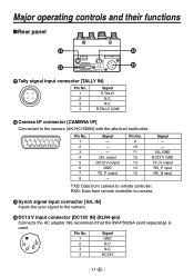
...PS505A (sold separately) is used. Pin No. 9 10 11 12 13 14 15 Signal - - Pin No. RXD: Data from camera to the camera. DC12 V input connector [DC12V IN] (XLR4-pin) Connects the AC adapter. G/L output DC12 V output GND TX_P output...Inputs the sync signal to remote controller. Signal 1 GND 2 N.C. 3 N.C. 4 DC12V - 11 (E) - R TALLY COM Camera I/F connector [CAMERA I/F] Connected to the camera (AK-HC1500G) with the attached multi cable. Major operating controls and their functions Rear panel Tally signal input connector [TALLY ...
...PS505A (sold separately) is used. Pin No. 9 10 11 12 13 14 15 Signal - - Pin No. RXD: Data from camera to the camera. DC12 V input connector [DC12V IN] (XLR4-pin) Connects the AC adapter. G/L output DC12 V output GND TX_P output...Inputs the sync signal to remote controller. Signal 1 GND 2 N.C. 3 N.C. 4 DC12V - 11 (E) - R TALLY COM Camera I/F connector [CAMERA I/F] Connected to the camera (AK-HC1500G) with the attached multi cable. Major operating controls and their functions Rear panel Tally signal input connector [TALLY ...
AKHRP150G User Guide
Page 15
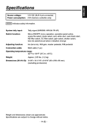
ENGLISH Specifications Source voltage: 12 V DC (XLR 4-pin connector) Power consumption: 3 W (Camera controller only) indicates safety information. System tally input: Tally signal (HIROSE: HR10A-7R-4P) Switch function: Menu ON/OFF, menu operation, operation panel active, scene ...
ENGLISH Specifications Source voltage: 12 V DC (XLR 4-pin connector) Power consumption: 3 W (Camera controller only) indicates safety information. System tally input: Tally signal (HIROSE: HR10A-7R-4P) Switch function: Menu ON/OFF, menu operation, operation panel active, scene ...
AKHRP150G User Guide
Page 84
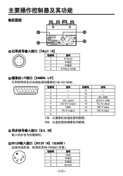
G/L GND DC12 V GND TX_N output RX_P input RX_N input 后面板 TALLY IN] 针脚号 1 2 3 4 信号 R TALLY R TALLY COM I/F接口 [CAMERA I/F AK-HC1500G)。 针脚号 信号 针脚号 1 - 9 2 - 10 3 - 11 4 G/L output 12 5 DC12 V output 13 6 GND 14 7 TX_P output 15 8 - TXD RXD G/L ...
G/L GND DC12 V GND TX_N output RX_P input RX_N input 后面板 TALLY IN] 针脚号 1 2 3 4 信号 R TALLY R TALLY COM I/F接口 [CAMERA I/F AK-HC1500G)。 针脚号 信号 针脚号 1 - 9 2 - 10 3 - 11 4 G/L output 12 5 DC12 V output 13 6 GND 14 7 TX_P output 15 8 - TXD RXD G/L ...


