
AWPH400 User Guide
Page 3
.... Keep the small memory cards such as power-supply cord or plug is required when the apparatus has been damaged in fire. 1 indicates safety information. The wide blade or the third prong are provided for your outlet, consult an electrician for future reference. 1) Read these instructions. 2) Keep these operating instructions carefully before using the unit. Use of another battery may explode if mistreated...
.... Keep the small memory cards such as power-supply cord or plug is required when the apparatus has been damaged in fire. 1 indicates safety information. The wide blade or the third prong are provided for your outlet, consult an electrician for future reference. 1) Read these instructions. 2) Keep these operating instructions carefully before using the unit. Use of another battery may explode if mistreated...

AWPH400 User Guide
Page 4
... precautions 2 Operating precautions 5 AW-PH400 Indoor Pan/Tilt Head 6 Introduction 6 Accessories 6 Precautions for use 6 Installation precautions 7 Parts and their function 8 Installation 12 $ Assembling the pan/tilt head 12 $ Setting the mounting direction switch 14 $ Setting the PCB switches 15 $ Installing the pan/tilt head 16 $ Mounting the camera 17 $ Attaching the wire 18 Replacing the consumable parts 19 Specifications 20 AW-RC400 Cable Compensation Unit 38 Introduction 38 Accessories 38 Parts and their...
... precautions 2 Operating precautions 5 AW-PH400 Indoor Pan/Tilt Head 6 Introduction 6 Accessories 6 Precautions for use 6 Installation precautions 7 Parts and their function 8 Installation 12 $ Assembling the pan/tilt head 12 $ Setting the mounting direction switch 14 $ Setting the PCB switches 15 $ Installing the pan/tilt head 16 $ Mounting the camera 17 $ Attaching the wire 18 Replacing the consumable parts 19 Specifications 20 AW-RC400 Cable Compensation Unit 38 Introduction 38 Accessories 38 Parts and their...

AWPH400 User Guide
Page 6
... 7 Camera cable 1 Tally lamp ...1 Tally mounting screws (M3!6 mm 2 Blank panel for tally 1 Wire mounting screws (with a total weight of 17.6 lbs (8 kg) can be mounted on replacing the battery in accordance with the general household garbage. Replace the lithium battery here. 6 For the procedure to remove the battery, refer to the section on the unit. ≥ The camera can also be rotated using...
... 7 Camera cable 1 Tally lamp ...1 Tally mounting screws (M3!6 mm 2 Blank panel for tally 1 Wire mounting screws (with a total weight of 17.6 lbs (8 kg) can be mounted on replacing the battery in accordance with the general household garbage. Replace the lithium battery here. 6 For the procedure to remove the battery, refer to the section on the unit. ≥ The camera can also be rotated using...

AWPH400 User Guide
Page 10
... selected signals are output from the VIDEO connector and the Y, Pr and Pb connectors. It is connected to the Y/VIDEO connector on the AW-PB504 SDI card or other card installed in the convertible camera. Use a BNC coaxial cable for the camera's video signals. A LENS I/F (2) connector [LENS I CABLE COMP OFF/ON switch [CABLE COMP] When this is set to ON, signals which the camera is to be mounted. > Camera mounting screws (U1/4" 20UNC) These are used when the mounting direction...
... selected signals are output from the VIDEO connector and the Y, Pr and Pb connectors. It is connected to the Y/VIDEO connector on the AW-PB504 SDI card or other card installed in the convertible camera. Use a BNC coaxial cable for the camera's video signals. A LENS I/F (2) connector [LENS I CABLE COMP OFF/ON switch [CABLE COMP] When this is set to ON, signals which the camera is to be mounted. > Camera mounting screws (U1/4" 20UNC) These are used when the mounting direction...
AWPH400 User Guide
Page 14
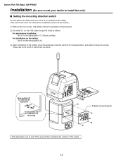
... it using the screws. (Take care not to turn off the power before changing the position of this switch. 14 Indoor Pan/Tilt Head AW-PH400 Installation (Be sure to ask your dealer to install the unit.) $ Setting the mounting direction switch Set the switch as follows when the unit is to be installed on the ceiling. (This switch was set to the stand-alone installation position at the factory...
... it using the screws. (Take care not to turn off the power before changing the position of this switch. 14 Indoor Pan/Tilt Head AW-PH400 Installation (Be sure to ask your dealer to install the unit.) $ Setting the mounting direction switch Set the switch as follows when the unit is to be installed on the ceiling. (This switch was set to the stand-alone installation position at the factory...
AWPH400 User Guide
Page 15
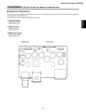
AW-PH400 Indoor Pan/Tilt Head AW-PH400 Installation (Be sure to ask your dealer to install the unit.) $ Setting the PCB switches The switches on the CONNECTOR PCB will need to be set in accordance with the signals to be transmitted and the equipment to be connected to the pan/tilt head. (The switches are set to support analog/SDI at the factory.) ≥ Analog/SDI support IP/IEEE switch: IEEE 422/IP switch: 422 ≥ Web card support IP/IEEE switch: IP 422/IP switch: IP ≥ IEEE1394 card support IP/IEEE switch: IEEE 422/IP switch: 422 IP/IEEE switch 422/IP switch 15
AW-PH400 Indoor Pan/Tilt Head AW-PH400 Installation (Be sure to ask your dealer to install the unit.) $ Setting the PCB switches The switches on the CONNECTOR PCB will need to be set in accordance with the signals to be transmitted and the equipment to be connected to the pan/tilt head. (The switches are set to support analog/SDI at the factory.) ≥ Analog/SDI support IP/IEEE switch: IEEE 422/IP switch: 422 ≥ Web card support IP/IEEE switch: IP 422/IP switch: IP ≥ IEEE1394 card support IP/IEEE switch: IEEE 422/IP switch: 422 IP/IEEE switch 422/IP switch 15

AWPH400 User Guide
Page 19
... part with a new one. (Battery used: CR2032 manganese dioxide-lithium battery) AW-PH400 $ How to be lost when the power is turned off , but if the internal battery has reached the end of approximately 5 years. Replacing the consumable parts Indoor Pan/Tilt Head AW-PH400 $ Replacing the battery The battery has a service life of its charge with the arrow from the direction of the new battery to operate...
... part with a new one. (Battery used: CR2032 manganese dioxide-lithium battery) AW-PH400 $ How to be lost when the power is turned off , but if the internal battery has reached the end of approximately 5 years. Replacing the consumable parts Indoor Pan/Tilt Head AW-PH400 $ Replacing the battery The battery has a service life of its charge with the arrow from the direction of the new battery to operate...

AWPH400 User Guide
Page 20
... Head AW-PH400 Specifications Supply voltage: AC 120 V, 60 Hz Power consumption: 145 W 1 indicates safety information. Genlock input: BNC Black burst or composite video signal Prompter input (PROMPTER IN): BNC Through output to PROMPTER connector Prompter output (PROMPTER OUT): D-SUB 15-pin Camera video output VIDEO: Y: Pr/C: Pb: SDI: BNC, 75-ohm output BNC, 75-ohm output BNC, 75-ohm output BNC, 75-ohm output BNC Camera, pan/tilt head control: RP/IP...
... Head AW-PH400 Specifications Supply voltage: AC 120 V, 60 Hz Power consumption: 145 W 1 indicates safety information. Genlock input: BNC Black burst or composite video signal Prompter input (PROMPTER IN): BNC Through output to PROMPTER connector Prompter output (PROMPTER OUT): D-SUB 15-pin Camera video output VIDEO: Y: Pr/C: Pb: SDI: BNC, 75-ohm output BNC, 75-ohm output BNC, 75-ohm output BNC, 75-ohm output BNC Camera, pan/tilt head control: RP/IP...

AWPH400 User Guide
Page 22
... same time. ≥ Up to ten tracing memories can be accommodated. ≥ Up to 50 preset memories can be set Rack-mounting adaptors 2 Mounting screws (M4!8 mm 4 22 Accessories Zoom switch 1 Plug (D-SUB 15-pin) for tally/INCOM system 1 set . ≥ The connection distance between the control panel and pan/tilt head system can be extended up to a maximum of 500 meters...
... same time. ≥ Up to ten tracing memories can be accommodated. ≥ Up to 50 preset memories can be set Rack-mounting adaptors 2 Mounting screws (M4!8 mm 4 22 Accessories Zoom switch 1 Plug (D-SUB 15-pin) for tally/INCOM system 1 set . ≥ The connection distance between the control panel and pan/tilt head system can be extended up to a maximum of 500 meters...

AWPH400 User Guide
Page 23
... AW-RP400 control panel is installed and used, it is set to [ON], the power supply from the connected pan/tilt heads to adjust the volume of the headset's receiver. 6 CALL button When this button is pressed, the buzzer of the joystick and zoom switch is adjusted when the OPERATE switch has been set to be installed, the EXT CONT switch on this switch is set to [OFF], the power supply from the connected pan...
... AW-RP400 control panel is installed and used, it is set to [ON], the power supply from the connected pan/tilt heads to adjust the volume of the headset's receiver. 6 CALL button When this button is pressed, the buzzer of the joystick and zoom switch is adjusted when the OPERATE switch has been set to be installed, the EXT CONT switch on this switch is set to [OFF], the power supply from the connected pan...

AWPH400 User Guide
Page 24
.../LOCK] button Use this to move even when the (9) IRIS dial is adjusted manually using the IRIS control on the control panel does not work when the WV-CB700A remote control box is set to MANU. MANU: The lens iris is turned. While MANU or LOCK is selected, the IRIS button lamp starts flashing quickly when the IRIS dial is turned: this dial while the (7) IRIS [AUTO/MANU/LOCK] button is connected to display...
.../LOCK] button Use this to move even when the (9) IRIS dial is adjusted manually using the IRIS control on the control panel does not work when the WV-CB700A remote control box is set to MANU. MANU: The lens iris is turned. While MANU or LOCK is selected, the IRIS button lamp starts flashing quickly when the IRIS dial is turned: this dial while the (7) IRIS [AUTO/MANU/LOCK] button is connected to display...

AWPH400 User Guide
Page 25
... tally connectors [1] to [5] of the AW-CB400 remote operation panel, if this button for two or more seconds to adjust the direction of the pan/tilt heads. E MENU/LIMIT button Hold down this panel is connected to the pan/tilt control panel, the lamps with the numbers corresponding to those connectors light up. When tally signals are displayed on . L PAN/TILT lever/ROTATION control switch Use these controls as...
... tally connectors [1] to [5] of the AW-CB400 remote operation panel, if this button for two or more seconds to adjust the direction of the pan/tilt heads. E MENU/LIMIT button Hold down this panel is connected to the pan/tilt control panel, the lamps with the numbers corresponding to those connectors light up. When tally signals are displayed on . L PAN/TILT lever/ROTATION control switch Use these controls as...

AWPH400 User Guide
Page 26
... cameras installed on the video switcher or other unit. S T U O TALLY/INCOM connector Connect this connector. 87654321 ?>= When even one WV-CB700A box is connected, the cameras cannot be controlled from the AW-CB400 remote operation panel even if the AW-CB400 is connected. Do not apply a voltage in excess of 5V to these connectors on the control panel or pan/tilt head lights. When the TALLY input connector is set...
... cameras installed on the video switcher or other unit. S T U O TALLY/INCOM connector Connect this connector. 87654321 ?>= When even one WV-CB700A box is connected, the cameras cannot be controlled from the AW-CB400 remote operation panel even if the AW-CB400 is connected. Do not apply a voltage in excess of 5V to these connectors on the control panel or pan/tilt head lights. When the TALLY input connector is set...

AWPH400 User Guide
Page 28
... than one setting is involved in the menu item, the settings on the bottom line are displayed when the MENU/LIMIT switch is held down for two or more seconds. DIRECTION TILT REVERSE ; DIRECTION SET ; DIRECTION PAN NORMAL ; PRIORITY ; Pan/Tilt Control Panel AW-RP400 Menu settings $ Operation method 1 The menu setting items are switched each time the dial is pressed. 4 When a setting is displayed, the setting can be changed by turning the...
... than one setting is involved in the menu item, the settings on the bottom line are displayed when the MENU/LIMIT switch is held down for two or more seconds. DIRECTION TILT REVERSE ; DIRECTION SET ; DIRECTION PAN NORMAL ; PRIORITY ; Pan/Tilt Control Panel AW-RP400 Menu settings $ Operation method 1 The menu setting items are switched each time the dial is pressed. 4 When a setting is displayed, the setting can be changed by turning the...

AWPH400 User Guide
Page 29
... have been connected, the priority of menu items and settings Menu item PRIORITY DIRECTION TILT RANGE SPEED WITH ZOOM POS. When MASTER is selected, the slave AW-RP400 has priority. MEMORY LENGTH PRESET SPEED IRIS CONTROL ROTATION SWITCH OPTION SWITCH CONTROL SELECT MODE BUZZER AUTO RUN SD CARD Setting PAN TILT ZOOM FOCUS IRIS ROTATION A B C D E F G H START No. AW-RP400 Menu settings $ List of the CONTROL SELECT buttons is performed using the master...
... have been connected, the priority of menu items and settings Menu item PRIORITY DIRECTION TILT RANGE SPEED WITH ZOOM POS. When MASTER is selected, the slave AW-RP400 has priority. MEMORY LENGTH PRESET SPEED IRIS CONTROL ROTATION SWITCH OPTION SWITCH CONTROL SELECT MODE BUZZER AUTO RUN SD CARD Setting PAN TILT ZOOM FOCUS IRIS ROTATION A B C D E F G H START No. AW-RP400 Menu settings $ List of the CONTROL SELECT buttons is performed using the master...

AWPH400 User Guide
Page 32
... CALL button has been pressed or when a tracing memory operation (record, play or change) is used to select the pan/tilt head and camera when the AW-CB400 remote operation panel has been connected to 30 seconds can be repeated. START No. (1 to 50): This sets the first number of the SD memory card to STOP No. Pan/Tilt Control Panel AW-RP400 Menu settings CONTROL SELECT MODE setting...
... CALL button has been pressed or when a tracing memory operation (record, play or change) is used to select the pan/tilt head and camera when the AW-CB400 remote operation panel has been connected to 30 seconds can be repeated. START No. (1 to 50): This sets the first number of the SD memory card to STOP No. Pan/Tilt Control Panel AW-RP400 Menu settings CONTROL SELECT MODE setting...

AWPH400 User Guide
Page 37
... AW-RP400 Supply voltage: DC 12.0 V Power consumption: Approx. 13 W 1 indicates safety information. Input connectors DC 12V IN: CONTROL IN FROM ROP: CONTROL IN FROM RCB: EXT CONT IN: REMOTE: XLR, 4 pins D-SUB 29-pin, cable supplied with AW-CB400 remote operation panel 10-pin round connector, cable supplied with WV-CB700A RJ45, additional AW-RP400 control signal input; 10BASE-T straight cable (UTP category 5), max. 500 meters 50-pin D-SUB connector, external control input, AW-CA50T9 Output connectors CONTROL OUT TO...
... AW-RP400 Supply voltage: DC 12.0 V Power consumption: Approx. 13 W 1 indicates safety information. Input connectors DC 12V IN: CONTROL IN FROM ROP: CONTROL IN FROM RCB: EXT CONT IN: REMOTE: XLR, 4 pins D-SUB 29-pin, cable supplied with AW-CB400 remote operation panel 10-pin round connector, cable supplied with WV-CB700A RJ45, additional AW-RP400 control signal input; 10BASE-T straight cable (UTP category 5), max. 500 meters 50-pin D-SUB connector, external control input, AW-CA50T9 Output connectors CONTROL OUT TO...

AWPH400 User Guide
Page 39
AW-RC400 Parts and their function Cable Compensation Unit AW-RC400 1 2 3 45 > =
AW-RC400 Parts and their function Cable Compensation Unit AW-RC400 1 2 3 45 > =
AWPH400 User Guide
Page 49
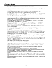
...; When using Y/C signals, connect the Y connectors and Pr/C connectors on the pan/tilt heads to the Y/VIDEO IN connectors and Pr/C IN connectors, respectively, on the AW-RC400 to switchers or monitors. 49 The maximum extension distance is a multiple number of cameras, one camera can be controlled from the AW-CB400. Power is 50 meters when using a UTP category 5 cable or its equivalent. Five cameras can be controlled from...
...; When using Y/C signals, connect the Y connectors and Pr/C connectors on the pan/tilt heads to the Y/VIDEO IN connectors and Pr/C IN connectors, respectively, on the AW-RC400 to switchers or monitors. 49 The maximum extension distance is a multiple number of cameras, one camera can be controlled from the AW-CB400. Power is 50 meters when using a UTP category 5 cable or its equivalent. Five cameras can be controlled from...
AWPH400 User Guide
Page 55
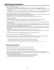
... recording of the PRESET MEMORY buttons No.11 to 10. 8 Select another pan/tilt head system using one of the button pressed now lights, and START button flashes. When registering data in such a button, delete the existing data in its memory first. 4 Press the number of memories in TRACING MEMORY buttons No.1 to 30. The pan/tilt head position and camera settings prevailing at any time...
... recording of the PRESET MEMORY buttons No.11 to 10. 8 Select another pan/tilt head system using one of the button pressed now lights, and START button flashes. When registering data in such a button, delete the existing data in its memory first. 4 Press the number of memories in TRACING MEMORY buttons No.1 to 30. The pan/tilt head position and camera settings prevailing at any time...


