
AWRP555N User Guide
Page 1
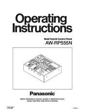
... MODE CAMBAR GAIN L H 5 1 ATW 2 0MdABANUUTO B WHT A BAL ABC OKNG PRESET 3 AWC 2 1 SCEUNSEEFRILE MENU ITEM MENU Multi Hybrid Control Panel AW-RP555 FOCUS LEFT YES DEF NO 10 LAMP UP PAN/TILT EX(TAF) ND WIP H/F OP RNOERTVIELRTSE REV DOWN RNOERPVAENRSE REV RIGHT Printed in Japan F0306Y0 D Before attempting to connect, operate or adjust this product, please read these instructions...
... MODE CAMBAR GAIN L H 5 1 ATW 2 0MdABANUUTO B WHT A BAL ABC OKNG PRESET 3 AWC 2 1 SCEUNSEEFRILE MENU ITEM MENU Multi Hybrid Control Panel AW-RP555 FOCUS LEFT YES DEF NO 10 LAMP UP PAN/TILT EX(TAF) ND WIP H/F OP RNOERTVIELRTSE REV DOWN RNOERPVAENRSE REV RIGHT Printed in Japan F0306Y0 D Before attempting to connect, operate or adjust this product, please read these instructions...

AWRP555N User Guide
Page 2
... IN ACCORDANCE WITH THE INSTALLATION INSTRUCTIONS. CAUTION: In order to maintain adequate ventilation, do not obstruct the ventilation. To prevent risk of the unit. This equipment generates, uses, and can radiate radio frequency energy, and if not installed and used in a commercial environment. Note: The rating plate (serial number plate) is operated in accordance with a protective earthing connection. These limits are designed...
... IN ACCORDANCE WITH THE INSTALLATION INSTRUCTIONS. CAUTION: In order to maintain adequate ventilation, do not obstruct the ventilation. To prevent risk of the unit. This equipment generates, uses, and can radiate radio frequency energy, and if not installed and used in a commercial environment. Note: The rating plate (serial number plate) is operated in accordance with a protective earthing connection. These limits are designed...

AWRP555N User Guide
Page 4
... pedestal adjustment 21 White balance adjustment 22 Black balance adjustment 23 Preset memory settings 24 Setting and changing the camera menu items 25 Attaching the rack mounting adapters 26 Replacement of consumable parts 26 How to change the position of the environment. Contents Introduction 4 Accessories 4 Parts and their functions 5 Control panel 5 Front panel switches 11 Rear connector panel 12 Connections 14 Operation 18 Turning on the pan/tilt head. Pan/tilt heads supported AW...
... pedestal adjustment 21 White balance adjustment 22 Black balance adjustment 23 Preset memory settings 24 Setting and changing the camera menu items 25 Attaching the rack mounting adapters 26 Replacement of consumable parts 26 How to change the position of the environment. Contents Introduction 4 Accessories 4 Parts and their functions 5 Control panel 5 Front panel switches 11 Rear connector panel 12 Connections 14 Operation 18 Turning on the pan/tilt head. Pan/tilt heads supported AW...
AWRP555N User Guide
Page 5
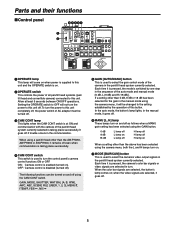
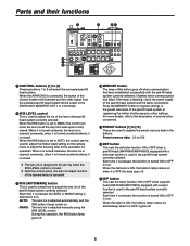
... taking place successfully. ON: Camera control is disabled (turned off). GAIN, MODE, SHUTTER, WHT BAL [A, B, ATW], AWC, ABC, SCENE FILE [USER, 1, 2, 3], MENU/ , ITEM/ , YES/ , NO/ GAIN [AUTO/MANU] button This is used to select the camera's video output signals in turn on ). when the video signals are selected, it is used to turn the power to this unit. Setting the OPERATE switch to OFF will not turn the control panel's camera control functions ON or OFF. When...
... taking place successfully. ON: Camera control is disabled (turned off). GAIN, MODE, SHUTTER, WHT BAL [A, B, ATW], AWC, ABC, SCENE FILE [USER, 1, 2, 3], MENU/ , ITEM/ , YES/ , NO/ GAIN [AUTO/MANU] button This is used to select the camera's video output signals in turn on ). when the video signals are selected, it is used to turn the power to this unit. Setting the OPERATE switch to OFF will not turn the control panel's camera control functions ON or OFF. When...
AWRP555N User Guide
Page 6
... [6 to 10] buttons start flashing alternately. 3. The shutter speed is actually switched as soon as the PRESET button is pressed. Parts and their functions OPERATE ON CAM CONT ON OFF OFF AUTO GAIN MANU 0dB L MODE H BAR CAM WHT BAL A B SHUTTER ATW TALLY 2 3 4 5 1 CONTROL 1 2 3 4 5 LEVEL IRIS 6 MEMORY AUTO MANU AWC SCENE FILE USER Multi Hybrid Control Panel AW-RP555 1 NG OK ABC 2 3 PRESET 2 3 4 7 8 9 MENU MENU ITEM YES...
... [6 to 10] buttons start flashing alternately. 3. The shutter speed is actually switched as soon as the PRESET button is pressed. Parts and their functions OPERATE ON CAM CONT ON OFF OFF AUTO GAIN MANU 0dB L MODE H BAR CAM WHT BAL A B SHUTTER ATW TALLY 2 3 4 5 1 CONTROL 1 2 3 4 5 LEVEL IRIS 6 MEMORY AUTO MANU AWC SCENE FILE USER Multi Hybrid Control Panel AW-RP555 1 NG OK ABC 2 3 PRESET 2 3 4 7 8 9 MENU MENU ITEM YES...
AWRP555N User Guide
Page 7
... AW-E860] When the [USER] button's lamp lights, the user mode is being adjusted, the AWC button's lamp flashes; For more details, refer to the "Setting and changing the camera menu items" (page 25). TALLY lamps [1] to [5] When tally signals are input to TALLY connectors [1] through [5], the lamps with the numbers corresponding to display the on-screen menus of the camera in the menu mode, the menu mode is selected. when it...
... AW-E860] When the [USER] button's lamp lights, the user mode is being adjusted, the AWC button's lamp flashes; For more details, refer to the "Setting and changing the camera menu items" (page 25). TALLY lamps [1] to [5] When tally signals are input to TALLY connectors [1] through [5], the lamps with the numbers corresponding to display the on-screen menus of the camera in the menu mode, the menu mode is selected. when it...
AWRP555N User Guide
Page 8
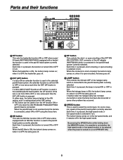
... turn. Each time it is OFF, the lamp goes off . MEMORY button The lamp of this control panel, the auto iris adjust function of the chosen number will illuminate and the video signal from wide open to fully closed . when it is pressed, the function is adjusted manually using the IRIS LEVEL control. Parts and their functions OPERATE ON CAM CONT ON OFF OFF AUTO GAIN MANU 0dB L MODE...
... turn. Each time it is OFF, the lamp goes off . MEMORY button The lamp of this control panel, the auto iris adjust function of the chosen number will illuminate and the video signal from wide open to fully closed . when it is pressed, the function is adjusted manually using the IRIS LEVEL control. Parts and their functions OPERATE ON CAM CONT ON OFF OFF AUTO GAIN MANU 0dB L MODE...
AWRP555N User Guide
Page 9
... connected or when the lamp has been disconnected or some other problem has occurred. SPEED button This is used in the pan/tilt head system currently selected. Parts and their functions OPERATE ON CAM CONT ON OFF OFF AUTO GAIN MANU 0dB L MODE H BAR CAM WHT BAL A B SHUTTER ATW TALLY 2 3 4 5 1 CONTROL 1 2 3 4 5 LEVEL IRIS 6 MEMORY AUTO MANU AWC SCENE FILE USER Multi Hybrid Control...
... connected or when the lamp has been disconnected or some other problem has occurred. SPEED button This is used in the pan/tilt head system currently selected. Parts and their functions OPERATE ON CAM CONT ON OFF OFF AUTO GAIN MANU 0dB L MODE H BAR CAM WHT BAL A B SHUTTER ATW TALLY 2 3 4 5 1 CONTROL 1 2 3 4 5 LEVEL IRIS 6 MEMORY AUTO MANU AWC SCENE FILE USER Multi Hybrid Control...
AWRP555N User Guide
Page 10
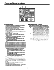
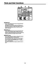
...system currently selected. Parts and their functions OPERATE ON CAM CONT ON OFF OFF AUTO GAIN MANU 0dB L MODE H BAR CAM WHT BAL A B SHUTTER ATW TALLY 2 3 4 5 1 CONTROL 1 2 3 4 5 LEVEL IRIS 6 MEMORY AUTO MANU AWC SCENE FILE USER Multi Hybrid Control Panel AW-RP555 1 NG OK ABC 2 3 PRESET 2 3 4 7 8 9 MENU MENU ITEM YES NO...(wide angle) is set by the direction in which the FOCUS lever is tilted, and the focus speed is adjusted by the angle to which the lever is panned in the L/R direction, the pan/tilt head direction changes to adjust the lens zoom in...
...system currently selected. Parts and their functions OPERATE ON CAM CONT ON OFF OFF AUTO GAIN MANU 0dB L MODE H BAR CAM WHT BAL A B SHUTTER ATW TALLY 2 3 4 5 1 CONTROL 1 2 3 4 5 LEVEL IRIS 6 MEMORY AUTO MANU AWC SCENE FILE USER Multi Hybrid Control Panel AW-RP555 1 NG OK ABC 2 3 PRESET 2 3 4 7 8 9 MENU MENU ITEM YES NO...(wide angle) is set by the direction in which the FOCUS lever is tilted, and the focus speed is adjusted by the angle to which the lever is panned in the L/R direction, the pan/tilt head direction changes to adjust the lens zoom in...

AWRP555N User Guide
Page 11
... the pan/tilt head system in the reverse directions. When the switch is set this switch to be performed by operating the ZOOM lever. When it is set to NOR, the point at shipment: NOR) This is used to REV, the panning operates in a stand-alone installation. Parts and their functions Front panel switches ZOOM REVERSE NOR REV ZOOM/FOCUS EXCHANGE...
... the pan/tilt head system in the reverse directions. When the switch is set this switch to be performed by operating the ZOOM lever. When it is set to NOR, the point at shipment: NOR) This is used to REV, the panning operates in a stand-alone installation. Parts and their functions Front panel switches ZOOM REVERSE NOR REV ZOOM/FOCUS EXCHANGE...

AWRP555N User Guide
Page 14
.../tilt head and convertible camera using the camera cable supplied with AW-PH360. Connect the iris control cable of the motorized zoom lens to the camera and the remote (zoom/focus control) cable to the pan/tilt head. When using the AW-PH360 as the pan/tilt head, set the controller selector switch on how to connect each component, refer to the operating instructions of at least...
.../tilt head and convertible camera using the camera cable supplied with AW-PH360. Connect the iris control cable of the motorized zoom lens to the camera and the remote (zoom/focus control) cable to the pan/tilt head. When using the AW-PH360 as the pan/tilt head, set the controller selector switch on how to connect each component, refer to the operating instructions of at least...

AWRP555N User Guide
Page 18
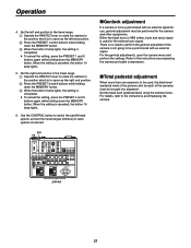
.... 1. Set this unit's OPERATE switch to EXTERNAL CONTROL OUT OFF. The lamps of both the MEMORY button and LAMP button start flashing, and the status currently set , proceed to the section entitled "Setting the travel range (limiters) of the AC adapter to ON. When the pan/tilt head system is connected (or changed) and its power is turned on the unit which is changed.) EXTERNAL CONTROL OUT setting Set this unit, and the camera's initial settings...
.... 1. Set this unit's OPERATE switch to EXTERNAL CONTROL OUT OFF. The lamps of both the MEMORY button and LAMP button start flashing, and the status currently set , proceed to the section entitled "Setting the travel range (limiters) of the AC adapter to ON. When the pan/tilt head system is connected (or changed) and its power is turned on the unit which is changed.) EXTERNAL CONTROL OUT setting Set this unit, and the camera's initial settings...

AWRP555N User Guide
Page 20
... system using the CONTROL button. 2. Set the upper limit position in the travel range (limiters) of the pan/tilt head Depending on the control panel to rotate the camera to the position which is to the operating instructions of the pan/tilt head system with such an obstacle. If the joystick is operated at this switch is not set the travel range. Operate...
... system using the CONTROL button. 2. Set the upper limit position in the travel range (limiters) of the pan/tilt head Depending on the control panel to rotate the camera to the position which is to the operating instructions of the pan/tilt head system with such an obstacle. If the joystick is operated at this switch is not set the travel range. Operate...
AWRP555N User Guide
Page 21
... no need to perform the genlock adjustment if the camera is to be synchronized with an external signal for use, genlock adjustment must be performed for each of the pictures shot by each system concerned. Genlock adjustment If a camera is not going to be brought into alignment. When the setting is canceled, the button 10 lamp lights. 6. Use the CONTROL button to the instructions accompanying the camera. OPERATE...
... no need to perform the genlock adjustment if the camera is to be synchronized with an external signal for use, genlock adjustment must be performed for each of the pictures shot by each system concerned. Genlock adjustment If a camera is not going to be brought into alignment. When the setting is canceled, the button 10 lamp lights. 6. Use the CONTROL button to the instructions accompanying the camera. OPERATE...

AWRP555N User Guide
Page 22
... conditions set simply by the new conditions. Similarly, with some light sources or color temperatures, it may not be possible for the white balance to be compensated properly. OPERATE ON CAM CONT ON OFF OFF AUTO GAIN MANU 0dB L MODE H BAR CAM WHT BAL A B SHUTTER ATW TALLY 2 3 4 5 1 CONTROL 1 2 3 4 5 LEVEL IRIS 6 MEMORY AUTO MANU AWC SCENE FILE USER Multi Hybrid Control Panel...
... conditions set simply by the new conditions. Similarly, with some light sources or color temperatures, it may not be possible for the white balance to be compensated properly. OPERATE ON CAM CONT ON OFF OFF AUTO GAIN MANU 0dB L MODE H BAR CAM WHT BAL A B SHUTTER ATW TALLY 2 3 4 5 1 CONTROL 1 2 3 4 5 LEVEL IRIS 6 MEMORY AUTO MANU AWC SCENE FILE USER Multi Hybrid Control Panel...

AWRP555N User Guide
Page 23
.../tilt head system using the CONTROL button. 2. Automatic adjustment of black balance 1. In this case, repeat the adjustment procedure. It may not be deleted and replaced by the new conditions. OPERATE ON CAM CONT ON OFF OFF AUTO GAIN MANU 0dB L MODE H BAR CAM WHT BAL A B SHUTTER ATW TALLY 2 3 4 5 1 CONTROL 1 2 3 4 5 LEVEL IRIS 6 MEMORY AUTO MANU AWC SCENE FILE USER Multi Hybrid Control Panel AW-RP555...
.../tilt head system using the CONTROL button. 2. Automatic adjustment of black balance 1. In this case, repeat the adjustment procedure. It may not be deleted and replaced by the new conditions. OPERATE ON CAM CONT ON OFF OFF AUTO GAIN MANU 0dB L MODE H BAR CAM WHT BAL A B SHUTTER ATW TALLY 2 3 4 5 1 CONTROL 1 2 3 4 5 LEVEL IRIS 6 MEMORY AUTO MANU AWC SCENE FILE USER Multi Hybrid Control Panel AW-RP555...
AWRP555N User Guide
Page 24
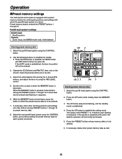
... using the CONTROL button. 2. Select the pan/tilt head system using the CONTROL button, and continue setting the preset memory data for entering the positions and settings with a preset memory function for each system concerned. If the AUTO mode is established, the lens iris position will be entered. 7. While the MEMORY button is held down the MEMORY button. 3 The OP button lamp starts flashing, and the standby mode...
... using the CONTROL button. 2. Select the pan/tilt head system using the CONTROL button, and continue setting the preset memory data for entering the positions and settings with a preset memory function for each system concerned. If the AUTO mode is established, the lens iris position will be entered. 7. While the MEMORY button is held down the MEMORY button. 3 The OP button lamp starts flashing, and the standby mode...

AWRP555N User Guide
Page 25
The menu mode is exited, and the on -screen menus of the camera in MENU mode, the MENU/ button, ITEM/ button, YES/ button and NO/ button correspond to the operating instructions of the camera. 3. Upon completion of the convertible camera as shown below. Setting and changing the camera menu items Setting procedure 1. If the MENU/ button is held down for at least two seconds while the MENU/ button lamp is lighted, the menu mode is established, and...
The menu mode is exited, and the on -screen menus of the camera in MENU mode, the MENU/ button, ITEM/ button, YES/ button and NO/ button correspond to the operating instructions of the camera. 3. Upon completion of the convertible camera as shown below. Setting and changing the camera menu items Setting procedure 1. If the MENU/ button is held down for at least two seconds while the MENU/ button lamp is lighted, the menu mode is established, and...
AWRP555N User Guide
Page 26
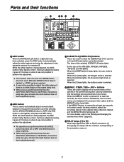
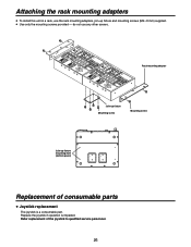
... part. do not use the rack mounting adapters, join-up fixture mounting hole (bottom panel) Replacement of the joystick to qualified service personnel. 26 Refer replacement of consumable parts Joystick replacement The joystick is impeded. HIGLHOW WIDE RNOEZRVOEORMSE REV 1 1 LEVEL 2 IRIS MAANUUTO ZOOM ZEOXOOCFMFH/FAONCGUES ON NEAR RFEOVCERUSSE NOR REV OPERATE ON OFF CO2N3 TROTLA3 LLYOFF 4 4 COCNATM ON SHUTTER MODE CAMBAR...
... part. do not use the rack mounting adapters, join-up fixture mounting hole (bottom panel) Replacement of the joystick to qualified service personnel. 26 Refer replacement of consumable parts Joystick replacement The joystick is impeded. HIGLHOW WIDE RNOEZRVOEORMSE REV 1 1 LEVEL 2 IRIS MAANUUTO ZOOM ZEOXOOCFMFH/FAONCGUES ON NEAR RFEOVCERUSSE NOR REV OPERATE ON OFF CO2N3 TROTLA3 LLYOFF 4 4 COCNATM ON SHUTTER MODE CAMBAR...

AWRP555N User Guide
Page 29
..., AW-E350, AW-E650, AW-E655, AW-E750, AW-E860 Input connectors DC 12V IN socket DC jack GND Please ground before using the unit. Input/Output connectors TALLY D-SUB, 15-pin REMOTE/SERVICE RS-232C TO PAN/TILT HEAD [1/EXT, 2 to 5] connectors RJ45 5, control signal output for pan/tilt heads Connecting cable: 10BASE-T straight cables (UTP category 5), max. 3,280 feet (1,000 meters) Other REMOTE/SERVICE switch Maintenance switch.
..., AW-E350, AW-E650, AW-E655, AW-E750, AW-E860 Input connectors DC 12V IN socket DC jack GND Please ground before using the unit. Input/Output connectors TALLY D-SUB, 15-pin REMOTE/SERVICE RS-232C TO PAN/TILT HEAD [1/EXT, 2 to 5] connectors RJ45 5, control signal output for pan/tilt heads Connecting cable: 10BASE-T straight cables (UTP category 5), max. 3,280 feet (1,000 meters) Other REMOTE/SERVICE switch Maintenance switch.


