
BTH1700 User Guide
Page 2
... operate the equipment. This problem does not occur as far as displaying extremely bright images on the screen of cathode-ray tube. DEGAUSS ● Do not use a diluted neutral cleanser, then wipe away the cleanser with input cards installed. Ⅵ HANDLING ● Avoid shocks or vibrations. Dangerous high voltages are no user-serviceable parts inside the unit. This monitor is equipped with a piece...
... operate the equipment. This problem does not occur as far as displaying extremely bright images on the screen of cathode-ray tube. DEGAUSS ● Do not use a diluted neutral cleanser, then wipe away the cleanser with input cards installed. Ⅵ HANDLING ● Avoid shocks or vibrations. Dangerous high voltages are no user-serviceable parts inside the unit. This monitor is equipped with a piece...
BTH1700 User Guide
Page 4
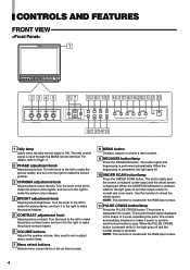
... make the picture redder, and turn it to the right to make the picture contrast higher. 6 VOLUME buttons Adjusts the speaker volume. Also used to Page 17. 2 PHASE adjustment knob Adjusts picture hue. NOTE: This function is input through the MAKE remote terminal. The synchronised signal displayed in the shape of a cross separating the parts. Use this function to check the whole screen. When the PULSE CROSS button is restored. The tally control signal is invalid with the RGB-input screen...
... make the picture redder, and turn it to the right to make the picture contrast higher. 6 VOLUME buttons Adjusts the speaker volume. Also used to Page 17. 2 PHASE adjustment knob Adjusts picture hue. NOTE: This function is input through the MAKE remote terminal. The synchronised signal displayed in the shape of a cross separating the parts. Use this function to check the whole screen. When the PULSE CROSS button is restored. The tally control signal is invalid with the RGB-input screen...
BTH1700 User Guide
Page 5
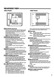
... the INPUT SELECT buttons. 22 Power lamp Unlit : The main power is set to MODE 2 in the set on the front panel lights in the brightness signal or to confirm or adjust CHROMA or PHASE. Connect the provided AC power cord to pages 8 and 9 for controlling the monitor from an external unit. Use this function to confirm the white balance. I : ON ⅜ : OFF 27 AC inlet Power input connector. REAR/SIDE VIEW REMOTE MAKE RS...
... the INPUT SELECT buttons. 22 Power lamp Unlit : The main power is set to MODE 2 in the set on the front panel lights in the brightness signal or to confirm or adjust CHROMA or PHASE. Connect the provided AC power cord to pages 8 and 9 for controlling the monitor from an external unit. Use this function to confirm the white balance. I : ON ⅜ : OFF 27 AC inlet Power input connector. REAR/SIDE VIEW REMOTE MAKE RS...
BTH1700 User Guide
Page 6
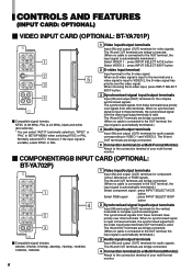
... video signals. CONTROLS AND FEATURES (INPUT CARD: OPTIONAL) Ⅵ VIDEO INPUT CARD (OPTIONAL: BT-YA701P) VIDEO 1 IN OUT VIDEO 2 1 IN OUT Y/C IN 2 EXT.SYNC 5 3 IN OUT AUDIO 1 IN OUT 4 AUDIO 2 Ⅵ Compatible signal formats: NTSC (3.58 MHz), PAL (4.43 MHz), black-and-white (50 Hz/60 Hz) * You can select "AUTO" (automatic selection), "NTSC" or "PAL" in SETUP MENU when switching NTSC or PAL. The IN and OUT terminals are bridge-connected. 4 Connection...
... video signals. CONTROLS AND FEATURES (INPUT CARD: OPTIONAL) Ⅵ VIDEO INPUT CARD (OPTIONAL: BT-YA701P) VIDEO 1 IN OUT VIDEO 2 1 IN OUT Y/C IN 2 EXT.SYNC 5 3 IN OUT AUDIO 1 IN OUT 4 AUDIO 2 Ⅵ Compatible signal formats: NTSC (3.58 MHz), PAL (4.43 MHz), black-and-white (50 Hz/60 Hz) * You can select "AUTO" (automatic selection), "NTSC" or "PAL" in SETUP MENU when switching NTSC or PAL. The IN and OUT terminals are bridge-connected. 4 Connection...
BTH1700 User Guide
Page 7
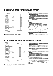
... 2 AUDIO 1 IN OUT 3 AUDIO 2 Ⅵ Compatible signal formats: 480/60i, 576/50i 1 Output terminal for a selected component serial digital signal Output terminal for s selected digital signal (the input displayed on the screen). NOTE: This input card cannot decode audio data even if contained in the input digital signal. 4 Connection terminal (to a Multi-Format Monitor) Attach to SDI 1 and SDI 2. NOTE: When the monitor's power is OFF, no digital signal is output. 2 Input terminals for component serial digital 4 signals Input...
... 2 AUDIO 1 IN OUT 3 AUDIO 2 Ⅵ Compatible signal formats: 480/60i, 576/50i 1 Output terminal for a selected component serial digital signal Output terminal for s selected digital signal (the input displayed on the screen). NOTE: This input card cannot decode audio data even if contained in the input digital signal. 4 Connection terminal (to a Multi-Format Monitor) Attach to SDI 1 and SDI 2. NOTE: When the monitor's power is OFF, no digital signal is output. 2 Input terminals for component serial digital 4 signals Input...
BTH1700 User Guide
Page 8
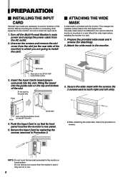
... to both right and left side). Turn off the Multi-Format Monitor's main power and unplug the power cable from the monitor's slots if they are not in so that its front panel touches the monitor's rear panel. 5. The wide mask cannot be sure to the guide rails. Mount the wide mask before installing the monitor in a rack. Insert the Input Card's board (greencoloured) into the slot, fitting the...
... to both right and left side). Turn off the Multi-Format Monitor's main power and unplug the power cable from the monitor's slots if they are not in so that its front panel touches the monitor's rear panel. 5. The wide mask cannot be sure to the guide rails. Mount the wide mask before installing the monitor in a rack. Insert the Input Card's board (greencoloured) into the slot, fitting the...
BTH1700 User Guide
Page 9
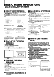
... be adjusted or set while watching the picture. when setting "UPPER" in an item Ⅵ HOW TO USE THE SUB MENU The sub menu function applies to be adjusted or set , Press the or buttons. ● To change the position of the sub menu screen, Set "UPPER" (on the top) or "LOWER" (on the input signal or combination of sub menu screen CONTRAST BRIGHT CHROMA PHASE NTSC SETUP COMPO.LEVEL sub menu reset :00...
... be adjusted or set while watching the picture. when setting "UPPER" in an item Ⅵ HOW TO USE THE SUB MENU The sub menu function applies to be adjusted or set , Press the or buttons. ● To change the position of the sub menu screen, Set "UPPER" (on the top) or "LOWER" (on the input signal or combination of sub menu screen CONTRAST BRIGHT CHROMA PHASE NTSC SETUP COMPO.LEVEL sub menu reset :00...
BTH1700 User Guide
Page 10
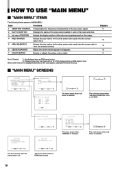
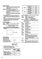
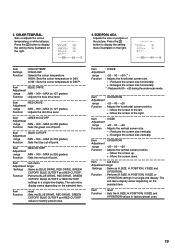
...:9. (for external control) 6 CENTER MARKER Makes the centre marker appear or disappear. 7 COLOR MATRIX Selects or adjusts the picture colour matrix. Items Functions 1 APERTURE CONTROL Compensates the frequency characteristics of the input video signal. 2 SLOT CONDITION Displays the status of the input cards installed in MAIN MENU. Displays *1 *2 *2 *2 *1 About "Displays" *1: Not displayed when an RGB signal is input. *2: Displayed only when the screen ratio is set to "UPPER". The sub menu screen when "sub menu POSITION" is 16:9.
...:9. (for external control) 6 CENTER MARKER Makes the centre marker appear or disappear. 7 COLOR MATRIX Selects or adjusts the picture colour matrix. Items Functions 1 APERTURE CONTROL Compensates the frequency characteristics of the input video signal. 2 SLOT CONDITION Displays the status of the input cards installed in MAIN MENU. Displays *1 *2 *2 *2 *1 About "Displays" *1: Not displayed when an RGB signal is input. *2: Displayed only when the screen ratio is set to "UPPER". The sub menu screen when "sub menu POSITION" is 16:9.
BTH1700 User Guide
Page 11
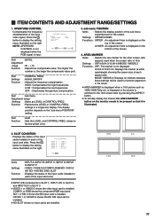
... Settings Function : INPUT A:/INPUT B:/INPUT C:/INPUT D:/INPUT E:/INPUT F: : VIDEO-1/VIDEO-2/COMPO./RGB/SDI 1/SDI 2/ HD SDI 1/HD SDI 2/NO SLOT : Displays the status of each aspect ratio. The higher the number is not displayed. 16:9/4:3/13:9/14:9: Displays the marker (a white quadrangle) showing the screen size of the input cards installed in the future. ● AREA MARKER is displayed on the screen. Item : sub menu Adjustment range/ Settings : Same as 1080i/1035i/720p etc. sub menu POSITION Items : Selects the display position...
... Settings Function : INPUT A:/INPUT B:/INPUT C:/INPUT D:/INPUT E:/INPUT F: : VIDEO-1/VIDEO-2/COMPO./RGB/SDI 1/SDI 2/ HD SDI 1/HD SDI 2/NO SLOT : Displays the status of each aspect ratio. The higher the number is not displayed. 16:9/4:3/13:9/14:9: Displays the marker (a white quadrangle) showing the screen size of the input cards installed in the future. ● AREA MARKER is displayed on the screen. Item : sub menu Adjustment range/ Settings : Same as 1080i/1035i/720p etc. sub menu POSITION Items : Selects the display position...
BTH1700 User Guide
Page 12
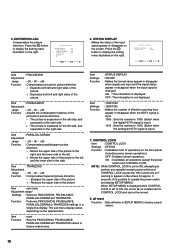
... marker disappears. ●To actually display the marker, the AREA MARKER button on the input signal format. SELECT :MANUAL R-Y PHASE :90 R/B GAIN :0.86 G-Y PHASE :244 G/B GAIN :0.30 sub menu reset EXIT: MENU ADJUST:- + SELECT: The menu screen when MANUAL is selected. ● The standard setting is set to "ITU601" or "ITU709" depending on the monitor needs to be used when the screen ratio is 16:9. (for function expansion...
... marker disappears. ●To actually display the marker, the AREA MARKER button on the input signal format. SELECT :MANUAL R-Y PHASE :90 R/B GAIN :0.86 G-Y PHASE :244 G/B GAIN :0.30 sub menu reset EXIT: MENU ADJUST:- + SELECT: The menu screen when MANUAL is selected. ● The standard setting is set to "ITU601" or "ITU709" depending on the monitor needs to be used when the screen ratio is 16:9. (for function expansion...
BTH1700 User Guide
Page 13
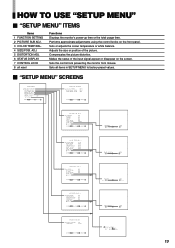
... :AUTO :STD. :000 EXIT: MENU ADJUST:- + SELECT: CONTRAST BRIGHT CHROMA PHASE NTSC SETUP COMPO.LEVEL sub menu reset :00 :00 :00 :00 :00 :SMPTE EXIT: MENU ADJUST:- + SELECT: COLOR TEMP. Compensates the picture distortion. Sets all items in SETUP MENU to factory-preset values. Ⅵ "SETUP MENU" SCREENS FUNCTION SETTING PICTURE SUB ADJ. COLOR TEMP./BAL. SIZE/POSI.ADJ. BLUE DRIVE RED DRIVE GREEN CUTOFF BLUE CUTOFF RED CUTOFF sub menu reset :LOW :000 :000 :000 :000 :000 EXIT: MENU ADJUST:- + SELECT: H.SIZE H.POSITION V.SIZE V.POSITION...
... :AUTO :STD. :000 EXIT: MENU ADJUST:- + SELECT: CONTRAST BRIGHT CHROMA PHASE NTSC SETUP COMPO.LEVEL sub menu reset :00 :00 :00 :00 :00 :SMPTE EXIT: MENU ADJUST:- + SELECT: COLOR TEMP. Compensates the picture distortion. Sets all items in SETUP MENU to factory-preset values. Ⅵ "SETUP MENU" SCREENS FUNCTION SETTING PICTURE SUB ADJ. COLOR TEMP./BAL. SIZE/POSI.ADJ. BLUE DRIVE RED DRIVE GREEN CUTOFF BLUE CUTOFF RED CUTOFF sub menu reset :LOW :000 :000 :000 :000 :000 EXIT: MENU ADJUST:- + SELECT: H.SIZE H.POSITION V.SIZE V.POSITION...
BTH1700 User Guide
Page 14
... the video input card is installed and an NTSC signal is pressed. B00 : Compliant with Betacam 7.5% set -up signal. 7.5 : Compliant with M2VTR signals. NOTE : COMPO. Function : Performs CONTRAST, BRIGHT, CHROMA, PHASE or COMPO. FUNCTION SETTING Selects the colour system and displays the monitor's powerup time or the total usage time. SLOW : The power supply starts approx. 3.2 seconds after the power switch is input. CONTRAST BRIGHT CHROMA PHASE NTSC SETUP COMPO.LEVEL sub menu reset...
... the video input card is installed and an NTSC signal is pressed. B00 : Compliant with Betacam 7.5% set -up signal. 7.5 : Compliant with M2VTR signals. NOTE : COMPO. Function : Performs CONTRAST, BRIGHT, CHROMA, PHASE or COMPO. FUNCTION SETTING Selects the colour system and displays the monitor's powerup time or the total usage time. SLOW : The power supply starts approx. 3.2 seconds after the power switch is input. CONTRAST BRIGHT CHROMA PHASE NTSC SETUP COMPO.LEVEL sub menu reset...
BTH1700 User Guide
Page 15
... BLUE DRIVE, RED DRIVE, GREEN CUTOFF, BLUE CUTOFF and RED CUTOFF values to the right. Item Function : reset : Sets the H.SIZE, H.POSITION, V.SIZE and V.POSITION values to display the setting menu illustrated on the right. ENGLISH 3. Sets or adjusts the colour temperature or white balance. Press the button to factory-preset ones. 15 Adjusts the size or position of the picture. Item : sub menu Adjustment range/ Settings : Same as H.SIZE, H.POSITION, V.SIZE and V.POSITION. Item : V.SIZE Adjustment range : -20 ~ 00 ~ +20 Function : Adjusts the vertical screen size...
... BLUE DRIVE, RED DRIVE, GREEN CUTOFF, BLUE CUTOFF and RED CUTOFF values to the right. Item Function : reset : Sets the H.SIZE, H.POSITION, V.SIZE and V.POSITION values to display the setting menu illustrated on the right. ENGLISH 3. Sets or adjusts the colour temperature or white balance. Press the button to factory-preset ones. 15 Adjusts the size or position of the picture. Item : sub menu Adjustment range/ Settings : Same as H.SIZE, H.POSITION, V.SIZE and V.POSITION. Item : V.SIZE Adjustment range : -20 ~ 00 ~ +20 Function : Adjusts the vertical screen size...
BTH1700 User Guide
Page 16
... digital HDTV signal is not displayed. OFF : The information is input.) 1035 : Sets the number to perform any operation except power switch and CONTROL LOCK causes the " Control lock on the screen for approx. 3 seconds. (It is possible to operate the power switch and display SETUP MENU.) When SETUP MENU is displayed while CONTROL LOCK is set to ON, attempting to 1035. (Select when the analogue HDTV signal is located next to factory-preset ones. all reset...
... digital HDTV signal is not displayed. OFF : The information is input.) 1035 : Sets the number to perform any operation except power switch and CONTROL LOCK causes the " Control lock on the screen for approx. 3 seconds. (It is possible to operate the power switch and display SETUP MENU.) When SETUP MENU is displayed while CONTROL LOCK is set to ON, attempting to 1035. (Select when the analogue HDTV signal is located next to factory-preset ones. all reset...
BTH1700 User Guide
Page 17
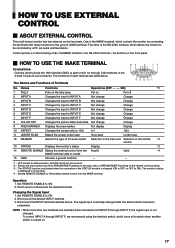
... is turned on the tally lamp. The signal input is in the 3-lines 15-pins D-sub connector. Control priority is actually changed after the disconnection has been completed. Not change Change 8 COLOR OFF Changes the picture black-and-white. Operation 1. the MAKE terminal > the RS-232C terminal > the buttons on Put off a switch when another switch is changed . Put on the front panel. Ⅵ HOW TO USE THE MAKE TERMINAL Connections Connect (short...
... is turned on the tally lamp. The signal input is in the 3-lines 15-pins D-sub connector. Control priority is actually changed after the disconnection has been completed. Not change Change 8 COLOR OFF Changes the picture black-and-white. Operation 1. the MAKE terminal > the RS-232C terminal > the buttons on Put off a switch when another switch is changed . Put on the front panel. Ⅵ HOW TO USE THE MAKE TERMINAL Connections Connect (short...
BTH1700 User Guide
Page 18
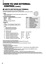
... (Data Terminal Ready) GND (Ground) DSR (Data Set Ready) RTS (Request To Send) CTS (Clear To Send) RI (Ring Indication) ID + Command + Data B Basic command D Command for adjusting the picture size S Command for adjusting the picture quality M Command for selecting the menu item F Command for selecting the menu item W Command for adjusting the white balance C Command for inquiring for details...
... (Data Terminal Ready) GND (Ground) DSR (Data Set Ready) RTS (Request To Send) CTS (Clear To Send) RI (Ring Indication) ID + Command + Data B Basic command D Command for adjusting the picture size S Command for adjusting the picture quality M Command for selecting the menu item F Command for selecting the menu item W Command for adjusting the white balance C Command for inquiring for details...
BTH1700 User Guide
Page 19
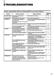
... the former one. 19 Is the monitor close to a motor, transformer or any cables connected to Standard (00) (or use the [reset] function). If none of the connected component ON? buttons. Is the audio cable disconnected? Has [CONTRAST] or [BRIGHT] been changed? ENGLISH TROUBLESHOOTING Solutions to common problems related to be checked Is the power plug loosened or disconnected? Connect the signal cable firmly. Set each picture adjustment item in [ PICTURE SUB ADJ.] in the screen.
... the former one. 19 Is the monitor close to a motor, transformer or any cables connected to Standard (00) (or use the [reset] function). If none of the connected component ON? buttons. Is the audio cable disconnected? Has [CONTRAST] or [BRIGHT] been changed? ENGLISH TROUBLESHOOTING Solutions to common problems related to be checked Is the power plug loosened or disconnected? Connect the signal cable firmly. Set each picture adjustment item in [ PICTURE SUB ADJ.] in the screen.
BTH1700 User Guide
Page 20
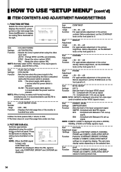
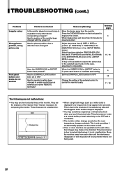
... MENU BLUE CHECK ASPECT AREA MARKER SLOT 1 SLOT 2 SLOT 3 A B C D E F INPUT SELECT POWER ● When a bright still image (such as well. ● If two or more than 30 minutes for a long period, it is not being used. 20 This is displayed. ● You may see two horizontal lines on the screen as a white cloth) is displayed for maximum effect. Has the picture position, size or distortion been changed...
... MENU BLUE CHECK ASPECT AREA MARKER SLOT 1 SLOT 2 SLOT 3 A B C D E F INPUT SELECT POWER ● When a bright still image (such as well. ● If two or more than 30 minutes for a long period, it is not being used. 20 This is displayed. ● You may see two horizontal lines on the screen as a white cloth) is displayed for maximum effect. Has the picture position, size or distortion been changed...
BTH1700 User Guide
Page 21
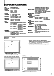
... MHz (-3 dB) Video (Y/C) : 8 MHz (-3 dB) Ⅲ Horizontal Resolution : Video (Y/C) : 600 TV lines 1080/60i : 800 TV lines Ⅲ Input Terminals : Installing an optional input card in SLOT 3 Ⅲ Compliant Video Signal : NTSC (3.58 MHz)/PAL (4.43 MHz) (using the BT-YA701P) 480i/576i/480p/1080i (60 Hz/24pSF)/720p (using the BT-YA702P) D1 serial digital (using the BT-YA703P) HD serial digital (using the BT-YA704P) Ⅲ Remote Inputs : •...
... MHz (-3 dB) Video (Y/C) : 8 MHz (-3 dB) Ⅲ Horizontal Resolution : Video (Y/C) : 600 TV lines 1080/60i : 800 TV lines Ⅲ Input Terminals : Installing an optional input card in SLOT 3 Ⅲ Compliant Video Signal : NTSC (3.58 MHz)/PAL (4.43 MHz) (using the BT-YA701P) 480i/576i/480p/1080i (60 Hz/24pSF)/720p (using the BT-YA702P) D1 serial digital (using the BT-YA703P) HD serial digital (using the BT-YA704P) Ⅲ Remote Inputs : •...
BTH1700 User Guide
Page 22
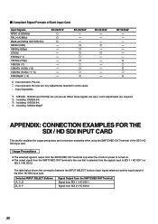
... SDI / HD SDI INPUT CARD This section explains the usage precautions and connection examples when using the SWITCHED OUT terminal of the SDI / HD SDI input card. Selected INPUT SELECT Buttons A, C, E B, D, F Signal Output from the SWITCHED OUT Terminal Signal from SDI 1 / HD SDI 1 Signal from the signals input to SDI 1 / HD SDI 1 or SDI 2 / HD SDI 2. Ⅵ Compliant Signal Formats of Each Input Card Input Signals NTSC (3.58 MHz) PAL (4.43 MHz) Black-and-White (50 Hz...
... SDI / HD SDI INPUT CARD This section explains the usage precautions and connection examples when using the SWITCHED OUT terminal of the SDI / HD SDI input card. Selected INPUT SELECT Buttons A, C, E B, D, F Signal Output from the SWITCHED OUT Terminal Signal from SDI 1 / HD SDI 1 Signal from the signals input to SDI 1 / HD SDI 1 or SDI 2 / HD SDI 2. Ⅵ Compliant Signal Formats of Each Input Card Input Signals NTSC (3.58 MHz) PAL (4.43 MHz) Black-and-White (50 Hz...


