
BTH1700BP User Guide
Page 2
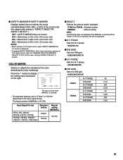
... time as well as displaying normal video playback motion images. 2 DEGAUSS • Do not use a diluted neutral cleanser, then wipe away the cleanser with input cards installed. Ⅵ HANDLING • Avoid shocks or vibrations. SCREEN BURN • It is operated in such a way no longer meets the standards of certification, and must therefore no user-serviceable parts inside the unit. Improper...
... time as well as displaying normal video playback motion images. 2 DEGAUSS • Do not use a diluted neutral cleanser, then wipe away the cleanser with input cards installed. Ⅵ HANDLING • Avoid shocks or vibrations. SCREEN BURN • It is operated in such a way no longer meets the standards of certification, and must therefore no user-serviceable parts inside the unit. Improper...
BTH1700BP User Guide
Page 4
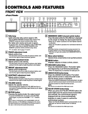
... COLOR OFF MENU BLUE CHECK ASPECT AREA MARKER SLOT 1 SLOT 2 SLOT 3 A B C D E F INPUT SELECT POWER 6 9 6 10 15 16 17 1 Tally lamp Lights when the tally control signal is invalid with the RGB-input screen. 13 PULSE CROSS button/lamp When you to adjust speaker volume. 7 MUTING button Pressing this function to check the whole screen. In this case, it easier to red or green. • To set -up menu screen. 10 MENU button Displays, adjusts or closes a menu screen. 11 DEGAUSS button...
... COLOR OFF MENU BLUE CHECK ASPECT AREA MARKER SLOT 1 SLOT 2 SLOT 3 A B C D E F INPUT SELECT POWER 6 9 6 10 15 16 17 1 Tally lamp Lights when the tally control signal is invalid with the RGB-input screen. 13 PULSE CROSS button/lamp When you to adjust speaker volume. 7 MUTING button Pressing this function to check the whole screen. In this case, it easier to red or green. • To set -up menu screen. 10 MENU button Displays, adjusts or closes a menu screen. 11 DEGAUSS button...
BTH1700BP User Guide
Page 5
The button lights and the screen changes in the under-scan mode. 18 INPUT SELECT button/lamp Selects an input signal from VIDEO 2 (INPUT SELECT B/D/F). *2 Notes • "NO SYNC" is displayed when no message is not input. The light goes off and the normal screen is set to "COLOR TEMP." Select SLOT1: press A or B Select SLOT2: press C or D Select SLOT3: press E or F Refer to the input card instructions on pages 7 and 8 for details...
The button lights and the screen changes in the under-scan mode. 18 INPUT SELECT button/lamp Selects an input signal from VIDEO 2 (INPUT SELECT B/D/F). *2 Notes • "NO SYNC" is displayed when no message is not input. The light goes off and the normal screen is set to "COLOR TEMP." Select SLOT1: press A or B Select SLOT2: press C or D Select SLOT3: press E or F Refer to the input card instructions on pages 7 and 8 for details...
BTH1700BP User Guide
Page 6
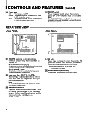
... AC inlet Power input connector. NOTE: It is OFF. Input cards are installed. 23 MAIN POWER switch Press the switch to SLOW in the set-up menu, it takes approx. 3.2 seconds for details. 25 Built-in stand-by mode). NOTE: When RUSH DELAY TIME is set to turn ON after the power switch is ON, the power lamp on the front panel lights in these slots. Connect the provided AC power cord to...
... AC inlet Power input connector. NOTE: It is OFF. Input cards are installed. 23 MAIN POWER switch Press the switch to SLOW in the set-up menu, it takes approx. 3.2 seconds for details. 25 Built-in stand-by mode). NOTE: When RUSH DELAY TIME is set to turn ON after the power switch is ON, the power lamp on the front panel lights in these slots. Connect the provided AC power cord to...
BTH1700BP User Guide
Page 7
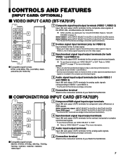
... are bridge-connected (auto termination). 2 S-video signal input terminal (only for VIDEO 2) Input terminal for component (color difference) or RGB signals. Refer to "EXT." CONTROLS AND FEATURES (INPUT CARD: OPTIONAL) 7 VIDEO INPUT CARD (BT-YA701P) VIDEO 1 IN OUT VIDEO 2 1 IN OUT Y/C IN 2 EXT.SYNC 3 IN OUT AUDIO 1 1 Composite signal input/output terminals (VIDEO 1,VIDEO 2) Input (IN) and output (OUT) terminals for both VIDEO 1 and VIDEO 2. • External synchronization does not function when a video signal (except black burst signal) is input to "SYNC SELECT...
... are bridge-connected (auto termination). 2 S-video signal input terminal (only for VIDEO 2) Input terminal for component (color difference) or RGB signals. Refer to "EXT." CONTROLS AND FEATURES (INPUT CARD: OPTIONAL) 7 VIDEO INPUT CARD (BT-YA701P) VIDEO 1 IN OUT VIDEO 2 1 IN OUT Y/C IN 2 EXT.SYNC 3 IN OUT AUDIO 1 1 Composite signal input/output terminals (VIDEO 1,VIDEO 2) Input (IN) and output (OUT) terminals for both VIDEO 1 and VIDEO 2. • External synchronization does not function when a video signal (except black burst signal) is input to "SYNC SELECT...
BTH1700BP User Guide
Page 9
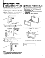
... not remove slot covers from the AC outlet. 2. Push the Input Card in a rack. This changes the viewable screen area to the 16:9 aspect ratio. • The wide mask cannot be sure to the guide rails. Caution: Use only the provided screws. Turn off the Multi-Format Monitor's main power and unplug the power cable from the monitor's slots if they are going to install the card. Ⅵ...
... not remove slot covers from the AC outlet. 2. Push the Input Card in a rack. This changes the viewable screen area to the 16:9 aspect ratio. • The wide mask cannot be sure to the guide rails. Caution: Use only the provided screws. Turn off the Multi-Format Monitor's main power and unplug the power cable from the monitor's slots if they are going to install the card. Ⅵ...
BTH1700BP User Guide
Page 10
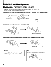
... the AC power cord. Attach the Power Cord Holder cover to open the cover. 10 Connect the AC power cord to make sure the plug doesn't pull out after the cover is attached. Hold until it clicks. a case and cover. 1. Caution: • A different plug shape will result in the cover being attached to a different position. • Check to the AC inlet, and join the Power Cord Holder cover with 2 screws (provided). 2. Press...
... the AC power cord. Attach the Power Cord Holder cover to open the cover. 10 Connect the AC power cord to make sure the plug doesn't pull out after the cover is attached. Hold until it clicks. a case and cover. 1. Caution: • A different plug shape will result in the cover being attached to a different position. • Check to the AC inlet, and join the Power Cord Holder cover with 2 screws (provided). 2. Press...
BTH1700BP User Guide
Page 11
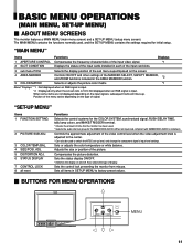
... COLOR OFF MENU SCREENS ASPECT AREA CHECK MARKER SLOT 1 SLOT 2 SLOT 3 A B C D E F INPUT SELECT POWER MUTING VOLUME DEGAUSS MENU MENU 11 "MAIN MENU" Items Functions Displays 1 APERTURE CONTROL Compensates the frequency characteristics of the input video signal. *1 2 SLOT CONDITION Displays the status of the video control level when the video adjustment knob is adjusted to the center. * Can also be used . * Selects the audio channel group for initial setup. Not displayed when an RGB signal is 16:9. Compensates the picture...
... COLOR OFF MENU SCREENS ASPECT AREA CHECK MARKER SLOT 1 SLOT 2 SLOT 3 A B C D E F INPUT SELECT POWER MUTING VOLUME DEGAUSS MENU MENU 11 "MAIN MENU" Items Functions Displays 1 APERTURE CONTROL Compensates the frequency characteristics of the input video signal. *1 2 SLOT CONDITION Displays the status of the video control level when the video adjustment knob is adjusted to the center. * Can also be used . * Selects the audio channel group for initial setup. Not displayed when an RGB signal is 16:9. Compensates the picture...
BTH1700BP User Guide
Page 12
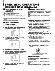
CONTRAST BRIGHT CHROMA PHASE NTSC SETUP COMPO.LEVEL sub menu reset : 00 : 00 : 00 : 00 : 00 :SMPTE EXIT: MENU ADJUST: - + SELECT: 3. Example: Setting an item in the MENU. Press the and/or buttons as many times as required to factory-preset values. by pressing the button several times, then press the button. COLOR TEMP./BAL. menu is restored. ¶ To change the position of the screen. 4. Select " sub menu" by...
CONTRAST BRIGHT CHROMA PHASE NTSC SETUP COMPO.LEVEL sub menu reset : 00 : 00 : 00 : 00 : 00 :SMPTE EXIT: MENU ADJUST: - + SELECT: 3. Example: Setting an item in the MENU. Press the and/or buttons as many times as required to factory-preset values. by pressing the button several times, then press the button. COLOR TEMP./BAL. menu is restored. ¶ To change the position of the screen. 4. Select " sub menu" by...

BTH1700BP User Guide
Page 14
.../RGB input card is displayed its name. (Example: HDSDI-1*) • The "--" indication may appear. sub menu POSI. LINE : Displays the area with EMBEDDED AUDIO, an asterisk (*) is installed. OFF: Does not zoom. BLK.+L : The area of the specified screen ratio is operated. • To adjust the zoom picture size, refer to ON via external control. • Use the MAKE/TRIGGER terminal for external control of the input video signal...
.../RGB input card is displayed its name. (Example: HDSDI-1*) • The "--" indication may appear. sub menu POSI. LINE : Displays the area with EMBEDDED AUDIO, an asterisk (*) is installed. OFF: Does not zoom. BLK.+L : The area of the specified screen ratio is operated. • To adjust the zoom picture size, refer to ON via external control. • Use the MAKE/TRIGGER terminal for external control of the input video signal...
BTH1700BP User Guide
Page 15
.... Press the button to display the setting menu illustrated on the input signal format. SELECT R-Y PHASE R/B GAIN G-Y PHASE G/B GAIN sub menu reset : MANUAL : 90 : 0.86 : 244 : 0.30 EXIT: MENU ADJUST: - + SELECT: The menu screen when MANUAL is selected. • The standard setting is 80% of the color demodulation (color rendering). When ITU601 or ITU709 is selected, they are displayed when MANUAL is selected. ITU601 or ITU709 : Standard setting MANUAL : Manual setting NOTE: The...
.... Press the button to display the setting menu illustrated on the input signal format. SELECT R-Y PHASE R/B GAIN G-Y PHASE G/B GAIN sub menu reset : MANUAL : 90 : 0.86 : 244 : 0.30 EXIT: MENU ADJUST: - + SELECT: The menu screen when MANUAL is selected. • The standard setting is 80% of the color demodulation (color rendering). When ITU601 or ITU709 is selected, they are displayed when MANUAL is selected. ITU601 or ITU709 : Standard setting MANUAL : Manual setting NOTE: The...

BTH1700BP User Guide
Page 16
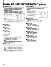
... TIME TALLY SELECT REMOTE SYSTEM E.AUDIO GROUP HOUR METER X100h : AUTO : INT. : STD. : GREEN : MAKE : 1G : 000 EXIT: MENU ADJUST: - + SELECT: ੬ See page 20. CONTRAST BRIGHT CHROMA PHASE NTSC SETUP COMPO.LEVEL sub menu reset : 00 : 00 : 00 : 00 : 00 :SMPTE EXIT: MENU ADJUST: - + SELECT: COLOR TEMP. HOW TO USE "SET-UP MENU" 7 "SET-UP MENU" SCREENS SET-UP MENU Setting Items FUNCTION SETTING PICTURE SUB ADJ. BLUE DRIVE RED DRIVE GREEN CUTOFF BLUE CUTOFF RED CUTOFF sub menu reset : LOW : 000...
... TIME TALLY SELECT REMOTE SYSTEM E.AUDIO GROUP HOUR METER X100h : AUTO : INT. : STD. : GREEN : MAKE : 1G : 000 EXIT: MENU ADJUST: - + SELECT: ੬ See page 20. CONTRAST BRIGHT CHROMA PHASE NTSC SETUP COMPO.LEVEL sub menu reset : 00 : 00 : 00 : 00 : 00 :SMPTE EXIT: MENU ADJUST: - + SELECT: COLOR TEMP. HOW TO USE "SET-UP MENU" 7 "SET-UP MENU" SCREENS SET-UP MENU Setting Items FUNCTION SETTING PICTURE SUB ADJ. BLUE DRIVE RED DRIVE GREEN CUTOFF BLUE CUTOFF RED CUTOFF sub menu reset : LOW : 000...
BTH1700BP User Guide
Page 17
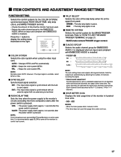
... number of channels receiving the signal. * About sound output level Sound output level is set to a standard output level for all 8 signal channels. COLOR SYSTEM SYNC SELECT RUSH DELAY TIME TALLY SELECT REMOTE SYSTEM E.AUDIO GROUP HOUR METER X100h : AUTO : INT. : STD. : GREEN : MAKE : 1G : 000 EXIT: MENU ADJUST: - + SELECT: 7 COLOR SYSTEM Selects the color system when using the video input card. 7 ITEM CONTENTS AND ADJUSTMENT RANGE/SETTINGS FUNCTION SETTING Selects the control systems for the COLOR...
... number of channels receiving the signal. * About sound output level Sound output level is set to a standard output level for all 8 signal channels. COLOR SYSTEM SYNC SELECT RUSH DELAY TIME TALLY SELECT REMOTE SYSTEM E.AUDIO GROUP HOUR METER X100h : AUTO : INT. : STD. : GREEN : MAKE : 1G : 000 EXIT: MENU ADJUST: - + SELECT: 7 COLOR SYSTEM Selects the color system when using the video input card. 7 ITEM CONTENTS AND ADJUSTMENT RANGE/SETTINGS FUNCTION SETTING Selects the control systems for the COLOR...
BTH1700BP User Guide
Page 18
... signal. Press the button to make fine adjustments between the monitors. BLUE DRIVE RED DRIVE GREEN CUTOFF BLUE CUTOFF RED CUTOFF sub menu reset : LOW : 000 : 000 : MIN : MIN : MIN EXIT: MENU ADJUST: - + SELECT: 7 COLOR TEMP. LOW : Sets the color temperature to 9300. When the PAL signal is input, only CONTRAST, BRIGHT and CHROMA are displayed. NOTE: NTSC SETUP is displayed only when the video input card is installed and an NTSC signal is input, only EXIT: MENU ADJUST: - + SELECT: CONTRAST and BRIGHT are displayed. 7 CONTRAST...
... signal. Press the button to make fine adjustments between the monitors. BLUE DRIVE RED DRIVE GREEN CUTOFF BLUE CUTOFF RED CUTOFF sub menu reset : LOW : 000 : 000 : MIN : MIN : MIN EXIT: MENU ADJUST: - + SELECT: 7 COLOR TEMP. LOW : Sets the color temperature to 9300. When the PAL signal is input, only CONTRAST, BRIGHT and CHROMA are displayed. NOTE: NTSC SETUP is displayed only when the video input card is installed and an NTSC signal is input, only EXIT: MENU ADJUST: - + SELECT: CONTRAST and BRIGHT are displayed. 7 CONTRAST...
BTH1700BP User Guide
Page 20
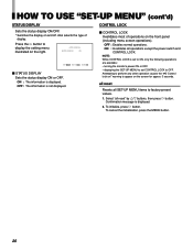
.... * Switches the display on the front panel (including menu screen operations). warning to factory-preset values. 1. all reset Resets all SET-UP MENU items to appear on the screen for approx. 3 seconds. ON : The information is displayed. 2. ON : Invalidates all reset" by / buttons, then press button. Attempting to ON, only the following operations are available: - Confirmation message is displayed. OFF : The information is set CONTROL LOCK to display the setting menu illustrated...
.... * Switches the display on the front panel (including menu screen operations). warning to factory-preset values. 1. all reset Resets all SET-UP MENU items to appear on the screen for approx. 3 seconds. ON : The information is displayed. 2. ON : Invalidates all reset" by / buttons, then press button. Attempting to ON, only the following operations are available: - Confirmation message is displayed. OFF : The information is set CONTROL LOCK to display the setting menu illustrated...
BTH1700BP User Guide
Page 22
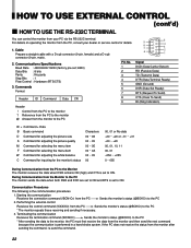
... (RTS/CTS) 3. Reference from the PC to the monitor @ Answer from the monitor to the PC ID + Command + Data B Basic command D Command for adjusting the picture size S Command for adjusting the picture quality M Command for selecting the menu item F Command for selecting the menu item W Command for adjusting the white balance C Command for inquiring for details. 9 4 1. If the PC does not...
... (RTS/CTS) 3. Reference from the PC to the monitor @ Answer from the monitor to the PC ID + Command + Data B Basic command D Command for adjusting the picture size S Command for adjusting the picture quality M Command for selecting the menu item F Command for selecting the menu item W Command for adjusting the white balance C Command for inquiring for details. 9 4 1. If the PC does not...
BTH1700BP User Guide
Page 23
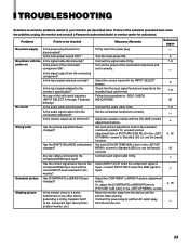
... installed input card format. Shaking picture Is the monitor close to your monitor are described here. No picture with the Is the signal cable disconnected? Connect the audio cable firmly. Or, adjust the [CONTRAST] or [BRIGHT] item in [PICTURE SUB ADJ.] in "SELF-CHECK INDICATIONS". Or, set each [COLOR TEMP./BAL.] item in the screen to the standard (centered) position. Has the WHITE BALANCE setting been changed ? Wrong color Has the picture adjustment been changed? TROUBLESHOOTING Solutions to common problems...
... installed input card format. Shaking picture Is the monitor close to your monitor are described here. No picture with the Is the signal cable disconnected? Connect the audio cable firmly. Or, adjust the [CONTRAST] or [BRIGHT] item in [PICTURE SUB ADJ.] in "SELF-CHECK INDICATIONS". Or, set each [COLOR TEMP./BAL.] item in the screen to the standard (centered) position. Has the WHITE BALANCE setting been changed ? Wrong color Has the picture adjustment been changed? TROUBLESHOOTING Solutions to common problems...
BTH1700BP User Guide
Page 24
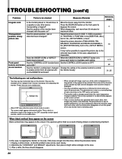
... control to be colored. Has the CONTROL LOCK function been set to degauss the screen. Press the DEGAUSS button on the front panel to ON? SIZE) or position (H. Adjust the picture distortion (PINCUSHION, PIN. Change the setting of static electricity on the side. Damper line VOLUME UNDER DEGAUSS SCAN PULSE CROSS COLOR OFF MENU BLUE CHECK ASPECT AREA MARKER SLOT 1 SLOT 2 SLOT 3 A B C D E F INPUT SELECT POWER • About CRT tube reflection (when Zoom mode...
... control to be colored. Has the CONTROL LOCK function been set to degauss the screen. Press the DEGAUSS button on the front panel to ON? SIZE) or position (H. Adjust the picture distortion (PINCUSHION, PIN. Change the setting of static electricity on the side. Damper line VOLUME UNDER DEGAUSS SCAN PULSE CROSS COLOR OFF MENU BLUE CHECK ASPECT AREA MARKER SLOT 1 SLOT 2 SLOT 3 A B C D E F INPUT SELECT POWER • About CRT tube reflection (when Zoom mode...
BTH1700BP User Guide
Page 25
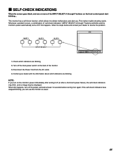
... 3 A B C D E F INPUT SELECT MUTING VOLUME UNDER DEGAUSS SCAN PULSE CROSS COLOR OFF MENU SCREENS ASPECT AREA CHECK MARKER SLOT 1 SLOT 2 SLOT 3 A B C D E F INPUT SELECT POWER 1. NOTE: If you turn off the main power switch on the front control panel start blinking... This makes trouble-shooting easier. Check which indicators are blinking. Whenever a problem occurs, a combination of "self-check indicators" (INPUT SELECT A through F buttons on the back of the INPUT SELECT A through F buttons) will blink and the monitor's power automatically turns off...
... 3 A B C D E F INPUT SELECT MUTING VOLUME UNDER DEGAUSS SCAN PULSE CROSS COLOR OFF MENU SCREENS ASPECT AREA CHECK MARKER SLOT 1 SLOT 2 SLOT 3 A B C D E F INPUT SELECT POWER 1. NOTE: If you turn off the main power switch on the front control panel start blinking... This makes trouble-shooting easier. Check which indicators are blinking. Whenever a problem occurs, a combination of "self-check indicators" (INPUT SELECT A through F buttons on the back of the INPUT SELECT A through F buttons) will blink and the monitor's power automatically turns off...
BTH1700BP User Guide
Page 26
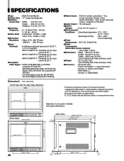
...) 7 Horizontal Resolution : Video (Y/C) : 600 TV lines 1080/60i : 800 TV lines 7 Input Terminals : Installing an optional input card in SLOT 1, 2, or 3 is inserted) 1.56 A (Max. 1.85 A) 7Dimensions : Width : 395 mm (15-5/8") Height : 334 mm (13-1/4") Depth : 466.5 mm (18-3/8") (not including wide mask and input card) 7 Weight : 23.7 kg (52.1 lbs) (not including wide mask and input card) 7Accessory : AC power cord : Power cord holder x 1 (case and cover) : Screws x 2 (Power cord holder) : Wide...
...) 7 Horizontal Resolution : Video (Y/C) : 600 TV lines 1080/60i : 800 TV lines 7 Input Terminals : Installing an optional input card in SLOT 1, 2, or 3 is inserted) 1.56 A (Max. 1.85 A) 7Dimensions : Width : 395 mm (15-5/8") Height : 334 mm (13-1/4") Depth : 466.5 mm (18-3/8") (not including wide mask and input card) 7 Weight : 23.7 kg (52.1 lbs) (not including wide mask and input card) 7Accessory : AC power cord : Power cord holder x 1 (case and cover) : Screws x 2 (Power cord holder) : Wide...


