
Service Manual
Page 3
.... Caution: (1) Use of controls or adjustments or performance of procedures other than those specified herein may result in hazardous radiation exposure. (2) The drive is a nonserviceable part. It should not service because the drive unit is designed to look into a computer-based system or unit which has an enclosing cover. For U.S.A. LASER...
.... Caution: (1) Use of controls or adjustments or performance of procedures other than those specified herein may result in hazardous radiation exposure. (2) The drive is a nonserviceable part. It should not service because the drive unit is designed to look into a computer-based system or unit which has an enclosing cover. For U.S.A. LASER...

Service Manual
Page 6
Specifications 1-1 2. Diagnosis Procedure 4-1 5. CONTENTS 1. Power-On Self Test (Boot Check 5-1 6. List of Parts 2-1 3. Names and Functions of Error Codes Block Diagram 3-1 4.
Specifications 1-1 2. Diagnosis Procedure 4-1 5. CONTENTS 1. Power-On Self Test (Boot Check 5-1 6. List of Parts 2-1 3. Names and Functions of Error Codes Block Diagram 3-1 4.

Service Manual
Page 10
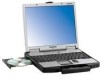
Names and Functions of Parts G H I J K A A L M N B I : LED indicator of microphones are connected, audio from the internal speakers is not heard. If other types H :LCD I C D O E P F Q A :Speaker J : Power switch B :USB port K :Function key C :...
Names and Functions of Parts G H I J K A A L M N B I : LED indicator of microphones are connected, audio from the internal speakers is not heard. If other types H :LCD I C D O E P F Q A :Speaker J : Power switch B :USB port K :Function key C :...

Service Manual
Page 18
... loaded? When you execute an automatic test 1.ɹ"Ctrl" + "F7" is pushed while the "Panasonic" start "PC-Diagnostic utility" again after the computer is selected on the screen of the breakdown part. 7-1 Setting of content of setup ɹɹɹɹ1.ɹThe power supply of the computer ...is turned on. ɹɹɹɹ2.ɹ" F2 " is pushed on the screen of "Panasonic" while " press " is displayed after doing the...
... loaded? When you execute an automatic test 1.ɹ"Ctrl" + "F7" is pushed while the "Panasonic" start "PC-Diagnostic utility" again after the computer is selected on the screen of the breakdown part. 7-1 Setting of content of setup ɹɹɹɹ1.ɹThe power supply of the computer ...is turned on. ɹɹɹɹ2.ɹ" F2 " is pushed on the screen of "Panasonic" while " press " is displayed after doing the...

Service Manual
Page 22
... ANTENNA PCB R JK2 JK1 Headphone Microphone KBD FPC KEYBOARD PCMCIA SLOT CN26 CN13 HDD PACK CN1301 SW1304 SW1301 Connector by Cable Direct connection by Connectors Parts on Bottom Side PAD SW PCB CN1302 SW1303 FLAT PAD 8-1
... ANTENNA PCB R JK2 JK1 Headphone Microphone KBD FPC KEYBOARD PCMCIA SLOT CN26 CN13 HDD PACK CN1301 SW1304 SW1301 Connector by Cable Direct connection by Connectors Parts on Bottom Side PAD SW PCB CN1302 SW1303 FLAT PAD 8-1

Service Manual
Page 23
...• Please execute writing BIOS ID when you exchange the Main Board. • You cannot reuse the Conductive Clothes and the heat dissi- Use new parts. 9.1.2. Slide the HDD Latch Knob (4), and then without releasing it, slide the DVD-ROM Drive Unit. (7) HDD Conductive Sheet HDD Earth Plate HDD Case... 1. pating parts such as Sheet and Rubber. Remove the HDD Damper. 3. Do not add peripherals while the computer is in the Suspend or hibernation mode; Preparation...
...• Please execute writing BIOS ID when you exchange the Main Board. • You cannot reuse the Conductive Clothes and the heat dissi- Use new parts. 9.1.2. Slide the HDD Latch Knob (4), and then without releasing it, slide the DVD-ROM Drive Unit. (7) HDD Conductive Sheet HDD Earth Plate HDD Case... 1. pating parts such as Sheet and Rubber. Remove the HDD Damper. 3. Do not add peripherals while the computer is in the Suspend or hibernation mode; Preparation...

Service Manual
Page 24
Removing the DIMM Memory Card DIMM Cover Hook Hook 2. Remove the four Screws and the KBD Angle L and R. 4. Lift the upper part of the Keyboard and draw it backward, release the six Hooks fixing the front side of the Center Cover and draw it backward, and then ... seven Hooks fixing the rear side of the DIMM Memory Card outward, and remove the DIMM Memory Card. Remove the Speaker L and R. 4. Lift the upper part of the Center Cover, and then remove the Center Cover. 3. KBD WP Sheet Connectors DIMM Memory Card 1. Remove the KBD FPC, Hooks 1. Remove the two...
Removing the DIMM Memory Card DIMM Cover Hook Hook 2. Remove the four Screws and the KBD Angle L and R. 4. Lift the upper part of the Keyboard and draw it backward, release the six Hooks fixing the front side of the Center Cover and draw it backward, and then ... seven Hooks fixing the rear side of the DIMM Memory Card outward, and remove the DIMM Memory Card. Remove the Speaker L and R. 4. Lift the upper part of the Center Cover, and then remove the Center Cover. 3. KBD WP Sheet Connectors DIMM Memory Card 1. Remove the KBD FPC, Hooks 1. Remove the two...

Service Manual
Page 30
...the Inverter with the Inverter Case to the LCD Rear Cabinet. 4. Screws : XQN17+BJ6FJ LCD Unit Inverter Inverter Case LCD/INV. 9.2. Attention when CF-74 series is repaired • Please execute writing BIOS ID when you exchange the Main Board. • You cannot reuse the Conductive Clothes and the... heat dissipating parts such as Sheet and Rubber. Setting the LCD Unit and the Inverter 1. Connect the LCD/INV. Cable W-LAN PCB L W-LAN PCB R LCD...
...the Inverter with the Inverter Case to the LCD Rear Cabinet. 4. Screws : XQN17+BJ6FJ LCD Unit Inverter Inverter Case LCD/INV. 9.2. Attention when CF-74 series is repaired • Please execute writing BIOS ID when you exchange the Main Board. • You cannot reuse the Conductive Clothes and the... heat dissipating parts such as Sheet and Rubber. Setting the LCD Unit and the Inverter 1. Connect the LCD/INV. Cable W-LAN PCB L W-LAN PCB R LCD...

Service Manual
Page 31
... ribs.) LCD Rear Cabnet Pass the Cable through the notch and lead it downward. A A LCD Damper D 0~1mm Match the LCD Damper D to the upper part and lower part of the LCD Unit. Pass the Cable between the boss and rib. Pass the Cable through the notch and lead it downward. Attach the...
... ribs.) LCD Rear Cabnet Pass the Cable through the notch and lead it downward. A A LCD Damper D 0~1mm Match the LCD Damper D to the upper part and lower part of the LCD Unit. Pass the Cable between the boss and rib. Pass the Cable through the notch and lead it downward. Attach the...

Service Manual
Page 32
... the surface of the Cushion. Safety Working S1 A: Match the Cloth by Cushion edge 0~1mm 9-10 B Attach the Cloth along the surface of the metal part. 95~100mm Use the Cable covered with the Conductive Cloth only. Fold it does not come out of the EMI Sheet. Cloth 0~2mm Corner of...
... the surface of the Cushion. Safety Working S1 A: Match the Cloth by Cushion edge 0~1mm 9-10 B Attach the Cloth along the surface of the metal part. 95~100mm Use the Cable covered with the Conductive Cloth only. Fold it does not come out of the EMI Sheet. Cloth 0~2mm Corner of...

Service Manual
Page 33
S2 Safety Working Cable Sheet Corner of the Connector S1 part in the same length. Inverter Case S5 Safety Critical components Inverter 1. Tape Inverter Case S2 Safety Working Inverter Cable Pass the Cables through the notch. ... Case, and connect the Inverter Cable to the mark. Pass the Cable between the LCD and the Inverter Case. Fix the Connector of the metal part. 0~1mm TP Power Cable Pass the Cables over the "a" line. (Otherwise they push up the front surface.) 0~1mm Tape Fold it back and fix it...
S2 Safety Working Cable Sheet Corner of the Connector S1 part in the same length. Inverter Case S5 Safety Critical components Inverter 1. Tape Inverter Case S2 Safety Working Inverter Cable Pass the Cables through the notch. ... Case, and connect the Inverter Cable to the mark. Pass the Cable between the LCD and the Inverter Case. Fix the Connector of the metal part. 0~1mm TP Power Cable Pass the Cables over the "a" line. (Otherwise they push up the front surface.) 0~1mm Tape Fold it back and fix it...

Service Manual
Page 40
... Cable using the Tape. Match the end of the Tape. (0 to CN14) (CN14) on the back side. Tape Pass the Cable between the parts. (Avoid running over the parts.) Main PCB 9.2.11. Fix the PC Card Ejector to the Connector (CN14) on the back side. 3. Match the end of the Tape. (0 to...
... Cable using the Tape. Match the end of the Tape. (0 to CN14) (CN14) on the back side. Tape Pass the Cable between the parts. (Avoid running over the parts.) Main PCB 9.2.11. Fix the PC Card Ejector to the Connector (CN14) on the back side. 3. Match the end of the Tape. (0 to...

Service Manual
Page 52
...E22-6-3 E22-6-4 E22-6-5 E22-6-6 E23 E24 E25 S E26 E27 E28 E29 E30 E31 E32 PART NO. CF-74GCDADBM REF. When replacing any of these components, use only manufacturer's specified parts. mark have special characteristics important for safety. DL3U11600AAA DL3U21600AAA DL3U31600AAA DL3U41600AAA DL3U51600AAA DL3UP1602AAA DL3U11501AAA DL3U21501AAA N5ZZ00000128... DAMPER HDD CASE HOLDER HDD CN HDD CONDUCTIVE SHEET B HDD EARTH PLATE HDD CF74 KBD FPC UNIT DRIVE, DVD-ROM & CF-R/RW BEZEL ASSY MP DRIVE FPC UNIT LCD UNIT ASS'Y LCD PREPARATION UNIT LCD DAMPER A LCD DAMPER B LCD DAMPER C ...
...E22-6-3 E22-6-4 E22-6-5 E22-6-6 E23 E24 E25 S E26 E27 E28 E29 E30 E31 E32 PART NO. CF-74GCDADBM REF. When replacing any of these components, use only manufacturer's specified parts. mark have special characteristics important for safety. DL3U11600AAA DL3U21600AAA DL3U31600AAA DL3U41600AAA DL3U51600AAA DL3UP1602AAA DL3U11501AAA DL3U21501AAA N5ZZ00000128... DAMPER HDD CASE HOLDER HDD CN HDD CONDUCTIVE SHEET B HDD EARTH PLATE HDD CF74 KBD FPC UNIT DRIVE, DVD-ROM & CF-R/RW BEZEL ASSY MP DRIVE FPC UNIT LCD UNIT ASS'Y LCD PREPARATION UNIT LCD DAMPER A LCD DAMPER B LCD DAMPER C ...

Service Manual
Page 53
...E36 E37 E38 E1001 E1003 E1005 Accessories A1 A2 A3 A4 A5 A6 A7 Packing Material P1 P2 P3 P4 P5 Mechanical Parts K1 K2 K3 K4 K5 K6 K7 K8 K9 K10 K11 K12 K13 K14 K15 K16 K17 K18 K19 K20 K21 K23... K30 K31 K32 K33 K34 K35 K36 K37 K38 K39 K40 K41 K42 K43 UDQFRPH32 DFJS995YA DFJS987ZA DFJS992XA N2ABZJ000033 K1NB94BA0001 DL3UP1505AAA DL3UP1517AAA DFJK10T053DB S CF-AA1683AM3 S N4HUNTA00002 S DFQW5047ZA S K2CG3DR00003 DFJS954ZA DFHS9017ZA DFHR6207ZA DFPK1182YA DFPK1185ZA DFPE0827ZA DFPN0834ZA DFPN0835ZA DFUQ0110ZB DFMD7A65ZA-0 DFMD7A83ZA DFMD7A84ZA DFMD9098ZC DFMC0670YA DFMX0778ZA DFMX1223ZA DFMY5036YA...
...E36 E37 E38 E1001 E1003 E1005 Accessories A1 A2 A3 A4 A5 A6 A7 Packing Material P1 P2 P3 P4 P5 Mechanical Parts K1 K2 K3 K4 K5 K6 K7 K8 K9 K10 K11 K12 K13 K14 K15 K16 K17 K18 K19 K20 K21 K23... K30 K31 K32 K33 K34 K35 K36 K37 K38 K39 K40 K41 K42 K43 UDQFRPH32 DFJS995YA DFJS987ZA DFJS992XA N2ABZJ000033 K1NB94BA0001 DL3UP1505AAA DL3UP1517AAA DFJK10T053DB S CF-AA1683AM3 S N4HUNTA00002 S DFQW5047ZA S K2CG3DR00003 DFJS954ZA DFHS9017ZA DFHR6207ZA DFPK1182YA DFPK1185ZA DFPE0827ZA DFPN0834ZA DFPN0835ZA DFUQ0110ZB DFMD7A65ZA-0 DFMD7A83ZA DFMD7A84ZA DFMD9098ZC DFMC0670YA DFMX0778ZA DFMX1223ZA DFMY5036YA...

Service Manual
Page 56
..., 324, 335, 391, 507, 508, 518, 523 87, 90, 154, 180, 181, C 185, 254, 394, 442, 455, 479, 480, 485, 502, 514 PART NO. Replacement Parts List Note: Important Safety Notice Components identified by ! When replacing any of these components use only manufacturer's specified parts. CF-74GCDADBM REF. mark have special characteristics important for safety.
..., 324, 335, 391, 507, 508, 518, 523 87, 90, 154, 180, 181, C 185, 254, 394, 442, 455, 479, 480, 485, 502, 514 PART NO. Replacement Parts List Note: Important Safety Notice Components identified by ! When replacing any of these components use only manufacturer's specified parts. CF-74GCDADBM REF. mark have special characteristics important for safety.