

Installation Instructions
Page 1
... Mounting ) Installation V ( Wooden Header ) Installation VI( In Existing Construction ) Maintenance Practical Guide to comply with instructions could result in personal injury and/or property damage. INSTALLATION INSTRUCTIONS Ventilating Fan FV-05VQ3 FV-08VQ3 FV-11VQ3 FV-15VQ4 Panasonid READ AND SAVE THESE INSTRUCTIONS. Please retain this booklet for future reference. Please read these instructions carefully before attempting to install, operate or service the Panasonic Ventilating Fan...
... Mounting ) Installation V ( Wooden Header ) Installation VI( In Existing Construction ) Maintenance Practical Guide to comply with instructions could result in personal injury and/or property damage. INSTALLATION INSTRUCTIONS Ventilating Fan FV-05VQ3 FV-08VQ3 FV-11VQ3 FV-15VQ4 Panasonid READ AND SAVE THESE INSTRUCTIONS. Please retain this booklet for future reference. Please read these instructions carefully before attempting to install, operate or service the Panasonic Ventilating Fan...

Installation Instructions
Page 2
...used to have an extended service life with dolphin-shaped blades driven by a capacitor motor. A damper for safety. It also incorporates a thermal-cutoff for preventing counterflow is a spring-loaded, quick-release type. The grille covering the main body is provided. SUPPLIED ACCESSORIES FV-05VQ3 FV-08VQ3 FV-11VQ3 FV-15VQ4 Part...Capacitor Motor White I Suspension bracket II -- - ' 1 Suspension bracket III 1 DESCRIPTION These Panasonic ceiling mount ventilation fans use a sirocco fan with reduced energy consumption. Double orifice technology is designed to reduce noise. ...
...used to have an extended service life with dolphin-shaped blades driven by a capacitor motor. A damper for safety. It also incorporates a thermal-cutoff for preventing counterflow is a spring-loaded, quick-release type. The grille covering the main body is provided. SUPPLIED ACCESSORIES FV-05VQ3 FV-08VQ3 FV-11VQ3 FV-15VQ4 Part...Capacitor Motor White I Suspension bracket II -- - ' 1 Suspension bracket III 1 DESCRIPTION These Panasonic ceiling mount ventilation fans use a sirocco fan with reduced energy consumption. Double orifice technology is designed to reduce noise. ...

Installation Instructions
Page 3
...) 4 7 7/8 (200) 3 10 1/4 (261) 3 1/2 (90) FV-08VQ3 FV-11VQ3 FV-15VQ4 RD /1 / (2, i. / (The dimension in square brackets refers to FV-15VQ4 which is different from FV-08/11VQ3) 3 1 2 (90) r 1 (25) 1 (26 3/4 (45) / 5 0 I , for 19.2 inches on center joists, only use suspension bracket III, If more than 19.2 inches on center joists, use suspension bracket I (259) Ra . Part name 1 Grille 2 Adaptor 3 Fan...
...) 4 7 7/8 (200) 3 10 1/4 (261) 3 1/2 (90) FV-08VQ3 FV-11VQ3 FV-15VQ4 RD /1 / (2, i. / (The dimension in square brackets refers to FV-15VQ4 which is different from FV-08/11VQ3) 3 1 2 (90) r 1 (25) 1 (26 3/4 (45) / 5 0 I , for 19.2 inches on center joists, only use suspension bracket III, If more than 19.2 inches on center joists, use suspension bracket I (259) Ra . Part name 1 Grille 2 Adaptor 3 Fan...

Installation Instructions
Page 4
Air direction V Hz diameter Noise Power consumption Speed Air deliver at (inches) (sones) (W) (tr/min) 0.1" WG(cfm) Weight lb.(kg) FV-05VQ3 4 SPECIFICATIONS Duct Model No.
Air direction V Hz diameter Noise Power consumption Speed Air deliver at (inches) (sones) (W) (tr/min) 0.1" WG(cfm) Weight lb.(kg) FV-05VQ3 4 SPECIFICATIONS Duct Model No.

Installation Instructions
Page 5
...use in a ceiling thermally insulated to a value greater than R40. (This is needed for proper combustion and exhausting of gases through the flue (chimney) of fire, electric shock or injury to the service panel. Not for Heating Refrigeration and Air Conditioning Engineers (ASHRAE) and the local code authorities. Installation work and electrical... models are UL listed for installation in the manner intended by the National Fire Protection Association (NFPA), and the American Society for use only. This product must be installed in cooking area. (Fig .B) 3. Do not use to...
...use in a ceiling thermally insulated to a value greater than R40. (This is needed for proper combustion and exhausting of gases through the flue (chimney) of fire, electric shock or injury to the service panel. Not for Heating Refrigeration and Air Conditioning Engineers (ASHRAE) and the local code authorities. Installation work and electrical... models are UL listed for installation in the manner intended by the National Fire Protection Association (NFPA), and the American Society for use only. This product must be installed in cooking area. (Fig .B) 3. Do not use to...

Installation Instructions
Page 6
... A on center joists is 24 inches, connect suspension bracket II and DI (C4 mark to open the orifice cover. Before installation, open the orifice cover, Secure the fan body to adaptor by using thumb screw. (Fig.1) Press and hold the claw of orifice cover to C4 mark) as shown below : Adaptor - - As... bracket I Fig. 2-1 Suspension bracket III Fig. 2-2 Suspension bracket I ) 1. Claw -../ .,, lk Orifice cover oClifNi 0 104. 1 Thumb screw IMPORTANT: Remove the tape from damper and adaptor before installation. INSTALLATION I (JOIST MOUNTING-I Fig, 2-3 Suspension bracketI Fig. 2-4
... A on center joists is 24 inches, connect suspension bracket II and DI (C4 mark to open the orifice cover. Before installation, open the orifice cover, Secure the fan body to adaptor by using thumb screw. (Fig.1) Press and hold the claw of orifice cover to C4 mark) as shown below : Adaptor - - As... bracket I Fig. 2-1 Suspension bracket III Fig. 2-2 Suspension bracket I ) 1. Claw -../ .,, lk Orifice cover oClifNi 0 104. 1 Thumb screw IMPORTANT: Remove the tape from damper and adaptor before installation. INSTALLATION I (JOIST MOUNTING-I Fig, 2-3 Suspension bracketI Fig. 2-4

Installation Instructions
Page 7
... nuts, connect house power wires to ventilating fan wires: black to white; green to the fan body by using screw II (ST4.2X10). (Fig.4) 5. Install the suspension bracket to joists by using long screws (ST4.2X20) and secure it with duct tape or clamps. 7 Joist 0 Fan body 2 Long ...5 Refer to junction box knock-out hole. (Fig.5) 6. Remove junction box cover and secure conduit or stress relief to wiring diagram below. Replace the junction box cover. (Fig.5) Wiring diagram Fan body Red Junction box Motor Capacitor White" White White Neutra-l > Power Supply Black kBlac ...
... nuts, connect house power wires to ventilating fan wires: black to white; green to the fan body by using screw II (ST4.2X10). (Fig.4) 5. Install the suspension bracket to joists by using long screws (ST4.2X20) and secure it with duct tape or clamps. 7 Joist 0 Fan body 2 Long ...5 Refer to junction box knock-out hole. (Fig.5) 6. Remove junction box cover and secure conduit or stress relief to wiring diagram below. Replace the junction box cover. (Fig.5) Wiring diagram Fan body Red Junction box Motor Capacitor White" White White Neutra-l > Power Supply Black kBlac ...

Installation Instructions
Page 8
... bracket III 21 1/4-23 1/2 (540-597) suspension bracket II&III 3. Insert the suspension bracket into fan body (refering to step 2 of the installation I ) CONTINUED 8. Finish ceiling work and wiring. 4. Select the suspension bracket according to spacing A as shown and mount grille to fan body. ...motor humming noise. 0 / Ceiling inches (mm) Slot Ceiling Fig. 6 Mounting spring Grille Fig. 7 INSTALLATION II (JOIST MOUNTING-II) 1. Insert the suspension bracket into the adaptor and secure it to joists by using long screw (ST4.2X20). (Fig.8) Ensure that distance B (7/8 inch, 21.6mm) for...
... bracket III 21 1/4-23 1/2 (540-597) suspension bracket II&III 3. Insert the suspension bracket into fan body (refering to step 2 of the installation I ) CONTINUED 8. Finish ceiling work and wiring. 4. Select the suspension bracket according to spacing A as shown and mount grille to fan body. ...motor humming noise. 0 / Ceiling inches (mm) Slot Ceiling Fig. 6 Mounting spring Grille Fig. 7 INSTALLATION II (JOIST MOUNTING-II) 1. Insert the suspension bracket into the adaptor and secure it to joists by using long screw (ST4.2X20). (Fig.8) Ensure that distance B (7/8 inch, 21.6mm) for...

Installation Instructions
Page 9
...it to receptacle. (Fig.10) Fig.12-2 joist Fig.12-3 Receptacle Thumb screw plug connector Fig. 10 Screw II (ST4.2X10) Ai Screw driver 3 Screws joist Fig.12-4 2 Long screws (ST4.2X20) Joist Fig. 11 9 Insert the blower into Fan body 9 joists. (Fig.9) 5.... (Fig.10) 7, Secure the suspension bracket to joists by using thumb screw. (Fig.10) Fan body 0 6, Secure the fan body to joists as in vertical direction. (Fig.11) 8. Remove blower section. (Fig.12-2) 3 Screws O O a a Adaptor a a a Fig.12-1 3. INSTALLATION II ( JOIST MOUNTING-II ) CONTINUED 5, Insert the fan ...
...it to receptacle. (Fig.10) Fig.12-2 joist Fig.12-3 Receptacle Thumb screw plug connector Fig. 10 Screw II (ST4.2X10) Ai Screw driver 3 Screws joist Fig.12-4 2 Long screws (ST4.2X20) Joist Fig. 11 9 Insert the blower into Fan body 9 joists. (Fig.9) 5.... (Fig.10) 7, Secure the suspension bracket to joists by using thumb screw. (Fig.10) Fan body 0 6, Secure the fan body to joists as in vertical direction. (Fig.11) 8. Remove blower section. (Fig.12-2) 3 Screws O O a a Adaptor a a a Fig.12-1 3. INSTALLATION II ( JOIST MOUNTING-II ) CONTINUED 5, Insert the fan ...
Installation Instructions
Page 10
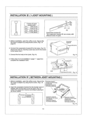
... ( BETWEEN JOIST MOUNTING ) 1. Connect the suspension bracket III to fan body. (Fig.13) (Select the hole by using thumb screw. (Fig.1 of installation I (page 7 - Follow step 5 to 9 of 16 inches and 19.2 inches page 6) horizental Joist Suspension bracket M 19.2 Inches vertical joist 2....the frame hole.) 3. Secure the Suspension bracket fan body to adaptor by using thumb screw. (Fig.1 of page 6) 2. Insert the suspension bracket into the bracket cover of • adaptor side and the back of I -joist. 1. Before installation, open the orifice cover. page 8) to the I -joist. (...
... ( BETWEEN JOIST MOUNTING ) 1. Connect the suspension bracket III to fan body. (Fig.13) (Select the hole by using thumb screw. (Fig.1 of installation I (page 7 - Follow step 5 to 9 of 16 inches and 19.2 inches page 6) horizental Joist Suspension bracket M 19.2 Inches vertical joist 2....the frame hole.) 3. Secure the Suspension bracket fan body to adaptor by using thumb screw. (Fig.1 of page 6) 2. Insert the suspension bracket into the bracket cover of • adaptor side and the back of I -joist. 1. Before installation, open the orifice cover. page 8) to the I -joist. (...

Installation Instructions
Page 11
... Joists Ensure that distance B (7/8 inch, 21.6mm) for the thickness of installation I (page 7 - Follow step 5 to complete the installation work. Insert the fan body between joists. Secure the suspension bracket to joists by using long screws (ST4.2X20). (Fig.17 , Fig.18) inches(mm) B... 7/8 (21,6) 2 Long screws (ST4.2X20) Fig. 16 Joist 5. Secure the suspension bracket to fan body by using screw II (ST4.2x10). (Fig.18) 6. INSTALLATION IV ( BETWEEN JOIST MOUNTING ) CONTINUED 3. page 8) to 9 of ceiling board. Joist .• • Fig. 17 2 Screw 11...
... Joists Ensure that distance B (7/8 inch, 21.6mm) for the thickness of installation I (page 7 - Follow step 5 to complete the installation work. Insert the fan body between joists. Secure the suspension bracket to joists by using long screws (ST4.2X20). (Fig.17 , Fig.18) inches(mm) B... 7/8 (21,6) 2 Long screws (ST4.2X20) Fig. 16 Joist 5. Secure the suspension bracket to fan body by using screw II (ST4.2x10). (Fig.18) 6. INSTALLATION IV ( BETWEEN JOIST MOUNTING ) CONTINUED 3. page 8) to 9 of ceiling board. Joist .• • Fig. 17 2 Screw 11...

Installation Instructions
Page 12
... be done and that area is sufficient for fan body. (next to adaptor by using long screws (ST4.2X20). (Fig.19, Fig.20) 4. Installation from accessible area above the planning installation location or existing ducting and wiring. (1) To install the fan body, follow the procedures described in an existing building requires an accessible area...
... be done and that area is sufficient for fan body. (next to adaptor by using long screws (ST4.2X20). (Fig.19, Fig.20) 4. Installation from accessible area above the planning installation location or existing ducting and wiring. (1) To install the fan body, follow the procedures described in an existing building requires an accessible area...

Installation Instructions
Page 13
... the ventilating fan. 2. Remove dust and dirt from fan body. Do not soak resin parts in water over 60°C. 1. Replace grille. Do not damp water to motor. 3. CAUTION: 1, Never use petrol, benzene, thinner or any dirt from fan body using a vacuum cleaner. (Fig.23) 4. Remove grille. (Squeeze mounting spring and pull down carefully...
... the ventilating fan. 2. Remove dust and dirt from fan body. Do not soak resin parts in water over 60°C. 1. Replace grille. Do not damp water to motor. 3. CAUTION: 1, Never use petrol, benzene, thinner or any dirt from fan body using a vacuum cleaner. (Fig.23) 4. Remove grille. (Squeeze mounting spring and pull down carefully...

Installation Instructions
Page 14
... placed directly over the fan housing in the attic. Our efficient, cool-running motors and our fluorescent bulbs do not create excessive heat that is a common problem with backdraft flap(s), Caulk termination to drywall, Short piece of Covers. No service information is maintained to support your product's warranty. (In the U.S.A., call center.) 14 Panasonic fans...
... placed directly over the fan housing in the attic. Our efficient, cool-running motors and our fluorescent bulbs do not create excessive heat that is a common problem with backdraft flap(s), Caulk termination to drywall, Short piece of Covers. No service information is maintained to support your product's warranty. (In the U.S.A., call center.) 14 Panasonic fans...

Installation Instructions
Page 15
PANASONIC CONSUMER ELECTRONICS COMPANY Division of Panasonic Corporation of North America, One Panasonic Way, Secaucus, NJ 07094 PANASONIC CANADA INC. 5770 Ambler Driver, Mississauga, ON L4W 2T3 www.panasonic.com X1204-8189 08VQ34020G
PANASONIC CONSUMER ELECTRONICS COMPANY Division of Panasonic Corporation of North America, One Panasonic Way, Secaucus, NJ 07094 PANASONIC CANADA INC. 5770 Ambler Driver, Mississauga, ON L4W 2T3 www.panasonic.com X1204-8189 08VQ34020G