FV08VQCL6 User Guide
Page 1
... (Replacement of lamp) 11 Practical Guide To Installation Back cover Specifications Product Service Back cover Back cover READ AND SAVE THESE INSTRUCTIONS Thank you for future reference. Please explain to users how to users. I (Joist Mounting - Please read these instructions carefully before attempting to comply with instructions could result in personal injury or property damage. Failure to install, operate or service the Panasonic product...
... (Replacement of lamp) 11 Practical Guide To Installation Back cover Specifications Product Service Back cover Back cover READ AND SAVE THESE INSTRUCTIONS Thank you for future reference. Please explain to users how to users. I (Joist Mounting - Please read these instructions carefully before attempting to comply with instructions could result in personal injury or property damage. Failure to install, operate or service the Panasonic product...

FV08VQCL6 User Guide
Page 2
... symbol is used to alert users to a specific operating procedure that could result in minor injury. O Installation work and electrical wiring must be performed. 0I This symbol is used to alert users not to disassemble the equipment. 0 This symbol is used to alert users to make sure of fuel burning equipment to a GFCI(Ground Fault Circuit Interrupter) - Follow the heating equipment manufacturer...
... symbol is used to alert users to a specific operating procedure that could result in minor injury. O Installation work and electrical wiring must be performed. 0I This symbol is used to alert users not to disassemble the equipment. 0 This symbol is used to alert users to make sure of fuel burning equipment to a GFCI(Ground Fault Circuit Interrupter) - Follow the heating equipment manufacturer...

FV08VQCL6 User Guide
Page 3
...electric service supply voltage is to no longer be properly grounded. O A statement to the effect that when the product is AC 120V, 60Hz. Prohibited Follow all local electrical and safety codes, as well as mounting fixtures, must be used , it must be used if such parts...Prohibited 0 For general ventilating use to prevent it from sharp edges, oil, grease, hot surfaces, chemicals or other objects. O Do not install with any solid-state speed control device. Prohibited Always disconnect the power source before working on or near the fan, motor, light fixture or junction box. ...
...electric service supply voltage is to no longer be properly grounded. O A statement to the effect that when the product is AC 120V, 60Hz. Prohibited Follow all local electrical and safety codes, as well as mounting fixtures, must be used , it must be used if such parts...Prohibited 0 For general ventilating use to prevent it from sharp edges, oil, grease, hot surfaces, chemicals or other objects. O Do not install with any solid-state speed control device. Prohibited Always disconnect the power source before working on or near the fan, motor, light fixture or junction box. ...

FV08VQCL6 User Guide
Page 4
..., if not installed and used in a particular installation. A damper for help. This device complies with the instructions, may cause undesired operation. The lighting unit is detected, when humidity increases rapidly, or when humidity rises above a 30% - 80% relative humidity set-point. These limits are no guarantee that turn on a circuit different from carton. These Panasonic ventilating fan models use a sirocco fan...
..., if not installed and used in a particular installation. A damper for help. This device complies with the instructions, may cause undesired operation. The lighting unit is detected, when humidity increases rapidly, or when humidity rises above a 30% - 80% relative humidity set-point. These limits are no guarantee that turn on a circuit different from carton. These Panasonic ventilating fan models use a sirocco fan...

FV08VQCL6 User Guide
Page 5
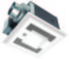
...Motion sensor unit 4 Junction box 5 Adaptor 6 Lens 7 Night lamp 8 Switch unit No. a- Part name 9 Lighting unit 10 Fluorescent lamp 11 Humidity sensor unit 12 Damper 13 Suspension bracket 14 Fan body 15 Bracket ... Black Neutral Live AC120V 60Hz (Power supply) (VENT.) Humidity sensor Motion sensor Adjustment Switch Fluorescent lamp (Self-ballasted) Night lamp Green (Earth ground) Black White Black Live (LIGHT) (Power supply) Neutral AC120V 60Hz Live AC120V 60Hz > (N.LIGHT) 5 Capacitor (114°c Fuse in Motor) Impedance - DIMENSIONS 0N 0 OD Cr CO O 2 0 ...
...Motion sensor unit 4 Junction box 5 Adaptor 6 Lens 7 Night lamp 8 Switch unit No. a- Part name 9 Lighting unit 10 Fluorescent lamp 11 Humidity sensor unit 12 Damper 13 Suspension bracket 14 Fan body 15 Bracket ... Black Neutral Live AC120V 60Hz (Power supply) (VENT.) Humidity sensor Motion sensor Adjustment Switch Fluorescent lamp (Self-ballasted) Night lamp Green (Earth ground) Black White Black Live (LIGHT) (Power supply) Neutral AC120V 60Hz Live AC120V 60Hz > (N.LIGHT) 5 Capacitor (114°c Fuse in Motor) Impedance - DIMENSIONS 0N 0 OD Cr CO O 2 0 ...

FV08VQCL6 User Guide
Page 6
... operation will influence the detecting precision as dust accumulates. " means "about 5%RH. Humidity preset switch may occasionally turn on blower unit Humidity preset switch positions (Tolerance:±10%) MIN -MAX -30% -40% -50% -60% -70% -80% Factory setting: - 50% RH ("- Human Fan activity w 9) Z Stop...► 0.5 1 2 3 5 10 20 30 60 Factory setting : 10 minutes. The distance that motion ti can be install over a tub or shower, for an adjustable duration of the O 90°. The "TIMER" controls how long the fan remains on and humidity change . PC•...
... operation will influence the detecting precision as dust accumulates. " means "about 5%RH. Humidity preset switch may occasionally turn on blower unit Humidity preset switch positions (Tolerance:±10%) MIN -MAX -30% -40% -50% -60% -70% -80% Factory setting: - 50% RH ("- Human Fan activity w 9) Z Stop...► 0.5 1 2 3 5 10 20 30 60 Factory setting : 10 minutes. The distance that motion ti can be install over a tub or shower, for an adjustable duration of the O 90°. The "TIMER" controls how long the fan remains on and humidity change . PC•...

FV08VQCL6 User Guide
Page 7
... bracket and the flange of frame to joists by using long screws (ST4.2X20) and secure it to 24 inches (609 mm) on center joists, please follow the installation step as shown below: Unit: inches (mm) 13 1/4 - 15 1/2 (336-394) 16 1/2 -18 3/4 (419-480) 21 1/4 - 23 1/2 (540-597) ... situation: A Spacing A is 16 inches (406 mm) to 24 inches (609 mm) on center joists Joists 1. INSTALLATION I Fig.1 2. If the spacing A is 16 inches (406 mm) to the fan body by using screw II (ST4.2X14). (Fig.2) Motion sensor unit 4 Long screws (ST4.2X20) Joist O o\ 0 2 Long screws (ST4.2X20...
... bracket and the flange of frame to joists by using long screws (ST4.2X20) and secure it to 24 inches (609 mm) on center joists, please follow the installation step as shown below: Unit: inches (mm) 13 1/4 - 15 1/2 (336-394) 16 1/2 -18 3/4 (419-480) 21 1/4 - 23 1/2 (540-597) ... situation: A Spacing A is 16 inches (406 mm) to 24 inches (609 mm) on center joists Joists 1. INSTALLATION I Fig.1 2. If the spacing A is 16 inches (406 mm) to the fan body by using screw II (ST4.2X14). (Fig.2) Motion sensor unit 4 Long screws (ST4.2X20) Joist O o\ 0 2 Long screws (ST4.2X20...

FV08VQCL6 User Guide
Page 8
Follow all the local electrical safety codes as well as the National Electrical Code (NEC). Ceiling hole should be aligned with the...junction box knock-out hole. (Fig.3) 6. Refer to relevant part of the flange. (Fig.5) IMPORTANT: Remove the tapes from louver and springs before installation. Install a circular duct and secure it with clamps, or wire ... duct is needed to connect to wiring diagram below : Tapes 04. As shown below . INSTALLATION I (JOIST MOUNTING -I ) CONTINUED 4. Using UL approved wire nuts, connect house power wires to prevent air leakage Fig.5 Note: Wiring detail...
Follow all the local electrical safety codes as well as the National Electrical Code (NEC). Ceiling hole should be aligned with the...junction box knock-out hole. (Fig.3) 6. Refer to relevant part of the flange. (Fig.5) IMPORTANT: Remove the tapes from louver and springs before installation. Install a circular duct and secure it with clamps, or wire ... duct is needed to connect to wiring diagram below : Tapes 04. As shown below . INSTALLATION I (JOIST MOUNTING -I ) CONTINUED 4. Using UL approved wire nuts, connect house power wires to prevent air leakage Fig.5 Note: Wiring detail...

FV08VQCL6 User Guide
Page 9
... so that lead wire of the grille ; Install light cover. (Fig.8) Fig.7 Rib Claw Insert plug connector Fig.9 Light cover C) Secure screw (M4X8) do* • Fig.8 11. Fix the lead wire of sensor unit into slot of lighting unit is not pinched. Fig.12 9 Remove...sensor unit into the clasp (1 position).(Fig.10) 13. Install the night lamp and fluorescent lamps. (Fig.7) Fluorescent lamp Gloves Lighting unit Grille Lighting unit Night lamp 10. If not, the lighting can't work. Remove light cover. (Fig.6) Light cover (I ) CONTINUED 8. Insert the grille mounting spring on...
... so that lead wire of the grille ; Install light cover. (Fig.8) Fig.7 Rib Claw Insert plug connector Fig.9 Light cover C) Secure screw (M4X8) do* • Fig.8 11. Fix the lead wire of sensor unit into slot of lighting unit is not pinched. Fig.12 9 Remove...sensor unit into the clasp (1 position).(Fig.10) 13. Install the night lamp and fluorescent lamps. (Fig.7) Fluorescent lamp Gloves Lighting unit Grille Lighting unit Night lamp 10. If not, the lighting can't work. Remove light cover. (Fig.6) Light cover (I ) CONTINUED 8. Insert the grille mounting spring on...

FV08VQCL6 User Guide
Page 10
Follow steps 4 to 14 of installation I (page 8, page 9) to complete the installation work . If the spacing A is 16 inches (406 mm) to complete the installation work . Install the suspension bracket to joists by using long screws (ST4.2X20)(Fig.14) and secure it to 11 1/2 inches (292 mm) r \ ir Joists inches ...joist Joists Suspension bracket I (ST4.2X6) 3. II) Joist situation: ir B Spacing B is 10 1/2 inches (266 mm) to the fan body by using screw II (ST4.2X14) (Fig.15) 4. Joist Fan body 18,1 a a 4 Long screws (ST4.2X20) Fig.16 10 Insert the suspension bracket ...
Follow steps 4 to 14 of installation I (page 8, page 9) to complete the installation work . If the spacing A is 16 inches (406 mm) to complete the installation work . Install the suspension bracket to joists by using long screws (ST4.2X20)(Fig.14) and secure it to 11 1/2 inches (292 mm) r \ ir Joists inches ...joist Joists Suspension bracket I (ST4.2X6) 3. II) Joist situation: ir B Spacing B is 10 1/2 inches (266 mm) to the fan body by using screw II (ST4.2X14) (Fig.15) 4. Joist Fan body 18,1 a a 4 Long screws (ST4.2X20) Fig.16 10 Insert the suspension bracket ...

FV08VQCL6 User Guide
Page 11
....22 11 Install light cover. (Fig.8 of Fig.21. Do not soak resin parts in water when cleaning. Remove by pulling down one mounting spring. Replace the fluorescent lamps (Maxlite MLS13GU35 13W) as shown in step (I (CLEANING) AWARNING O Disconnect power source before working on unit. Clean grille. (Don't put into hot water. Use non-abrasive kitchen detergent, wipe dry with clean cloth. (Fig.19...
....22 11 Install light cover. (Fig.8 of Fig.21. Do not soak resin parts in water when cleaning. Remove by pulling down one mounting spring. Replace the fluorescent lamps (Maxlite MLS13GU35 13W) as shown in step (I (CLEANING) AWARNING O Disconnect power source before working on unit. Clean grille. (Don't put into hot water. Use non-abrasive kitchen detergent, wipe dry with clean cloth. (Fig.19...

FV08VQCL6 User Guide
Page 12
...glue PVC joints) Fig.23 SPECIFICATIONS Model No. Clamps plus mastic or approved foil faced tape at 0.1"WG (cFM) Weight lb.( kg) FV-08VQCL6 Exhaust 120 60 4 or 6 PRACTICAL GUIDE TO INSTALLATION Properly insulate the area around the fan to minimize building heat loss and gain. (Fig.23...create excessive heat that is a common problem with mastic or approved foil faced tape 2-3 ft straight run before elbow In attic installation, caulk box to be placed directly over the fan housing in the attic. Panasonic fans and fan/light combination units do not create enough ambient heat to drywall...
...glue PVC joints) Fig.23 SPECIFICATIONS Model No. Clamps plus mastic or approved foil faced tape at 0.1"WG (cFM) Weight lb.( kg) FV-08VQCL6 Exhaust 120 60 4 or 6 PRACTICAL GUIDE TO INSTALLATION Properly insulate the area around the fan to minimize building heat loss and gain. (Fig.23...create excessive heat that is a common problem with mastic or approved foil faced tape 2-3 ft straight run before elbow In attic installation, caulk box to be placed directly over the fan housing in the attic. Panasonic fans and fan/light combination units do not create enough ambient heat to drywall...

