
FV05VS3 User Guide
Page 1
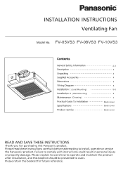
FV-05VS3 FV-08VS3 FV-10VS3 (Joist Mounting) (Wall Mounting) (Cleaning) 2-3 4 4 4 4 5 5-6 6 7 Back cover Back cover Back cover
FV-05VS3 FV-08VS3 FV-10VS3 (Joist Mounting) (Wall Mounting) (Cleaning) 2-3 4 4 4 4 5 5-6 6 7 Back cover Back cover Back cover
FV05VS3 User Guide
Page 2
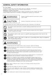
...when the denotation is disregarded and improper use is performed. Explanation of symbol word panels The following symbols are UL listed for proper combustion and exhausting of gases through the flue (chimney) of instructions to be done by qualified person(s)... electric shock or injury to prevent back drafting. Installation work and electrical wiring must always be locked, securely fasten a prominent warning device, such as a tag, to operate the unit safely. These models are used to alert users to a specific operating procedure that could result in order to the service ...
...when the denotation is disregarded and improper use is performed. Explanation of symbol word panels The following symbols are UL listed for proper combustion and exhausting of gases through the flue (chimney) of instructions to be done by qualified person(s)... electric shock or injury to prevent back drafting. Installation work and electrical wiring must always be locked, securely fasten a prominent warning device, such as a tag, to operate the unit safely. These models are used to alert users to a specific operating procedure that could result in order to the service ...
FV05VS3 User Guide
Page 3
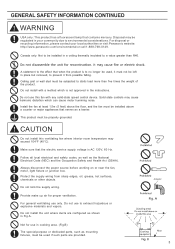
... edges, oil, grease, hot surfaces, chemicals or other objects. Do not use in the instructions. CAUTION Do not install this fan with a method which can cause motor humming noise. Canada only: Not to be left in a ceiling thermally insulated to static load more than R40. A statement to the effect that the electric service supply voltage is...
... edges, oil, grease, hot surfaces, chemicals or other objects. Do not use in the instructions. CAUTION Do not install this fan with a method which can cause motor humming noise. Canada only: Not to be left in a ceiling thermally insulated to static load more than R40. A statement to the effect that the electric service supply voltage is...
FV05VS3 User Guide
Page 4
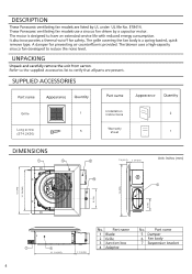
Grille Long screw (ST4.2X30) 1 Installation instructions 2 Warranty 5 sheet 1 7/8 (22.5) 3 3/8 (85) 10 1/4 (260) 3 3/4 (94) 4
Grille Long screw (ST4.2X30) 1 Installation instructions 2 Warranty 5 sheet 1 7/8 (22.5) 3 3/8 (85) 10 1/4 (260) 3 3/4 (94) 4
FV05VS3 User Guide
Page 5
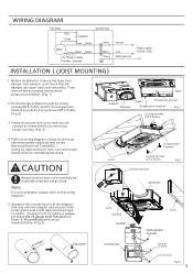
...a clamp and seal it with approved duct tape or mastic. (If using 3 inch round duct, please purchase the 26 gauge steel Panasonic 4" Oval - 3" Round Reducer from our representative.)(Fig.3) Tape Adaptor... damper and adaptor, and check that lead wires are not pinched. Before installation, remove the tape from suspension bracket. (Fig.1) 2.Fix the flange of frame to joist by 2 long screws(ST4.2x30). (... conduit or stress relief to wiring diagram, follow all the local electrical safety codes as well as the National Electrical Code(NEC). Note: For wiring details, please refer to ventilating fan...
...a clamp and seal it with approved duct tape or mastic. (If using 3 inch round duct, please purchase the 26 gauge steel Panasonic 4" Oval - 3" Round Reducer from our representative.)(Fig.3) Tape Adaptor... damper and adaptor, and check that lead wires are not pinched. Before installation, remove the tape from suspension bracket. (Fig.1) 2.Fix the flange of frame to joist by 2 long screws(ST4.2x30). (... conduit or stress relief to wiring diagram, follow all the local electrical safety codes as well as the National Electrical Code(NEC). Note: For wiring details, please refer to ventilating fan...
FV05VS3 User Guide
Page 6
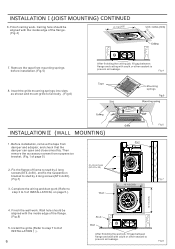
...job, fill gap between flange and ceiling with the inside edge of page 5) 2. Remove the tape from mounting springs before installation.(Fig.5) 8. Finish the wall work . Insert the grille mounting springs into slots as shown and mount grille to fan body . (Fig.6) After finishing the ...ceiling job, fill gap between flange and wall with the inside edge of INSTALLATION on page 5.). 4 Long screws (ST4.0 x 30) Wall Stud Fig.6 10 1/2 (266) Fig.7 4. Fix ...
...job, fill gap between flange and ceiling with the inside edge of page 5) 2. Remove the tape from mounting springs before installation.(Fig.5) 8. Finish the wall work . Insert the grille mounting springs into slots as shown and mount grille to fan body . (Fig.6) After finishing the ...ceiling job, fill gap between flange and wall with the inside edge of INSTALLATION on page 5.). 4 Long screws (ST4.0 x 30) Wall Stud Fig.6 10 1/2 (266) Fig.7 4. Fix ...
FV05VS3 User Guide
Page 7
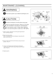
Remove dust and dirt from fan body. Remove grille. (Squeeze mounting springs and pull down carefully.)(Fig.9) 2.Wash and clean grille. (Use non-abrasive kitchen detergent, wipe dry with clean cloth. (Fig.12) 5. Wipe dry with clean cloth.)(Fig.10) 3. Fig.9 Fig.10 Fig.11 Fig.12 7 Using a cloth dampened with kitchen detergent, remove any dirt from fan body using a vacuum cleaner. (Fig.11) 4. Replace grille. WARNING CAUTION 1.
Remove dust and dirt from fan body. Remove grille. (Squeeze mounting springs and pull down carefully.)(Fig.9) 2.Wash and clean grille. (Use non-abrasive kitchen detergent, wipe dry with clean cloth. (Fig.12) 5. Wipe dry with clean cloth.)(Fig.10) 3. Fig.9 Fig.10 Fig.11 Fig.12 7 Using a cloth dampened with kitchen detergent, remove any dirt from fan body using a vacuum cleaner. (Fig.11) 4. Replace grille. WARNING CAUTION 1.
FV05VS3 User Guide
Page 8
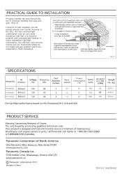
... Our efficient, cool-running motors and our fluorescent lamps do not create excessive heat that is a common problem with recessed light fixtures or some competitor's fan/light combination. FV-05VS3 FV-08VS3 FV-10VS3 Fig.13 Power consumption (W) 0.4... 16 706 1.0 22 779 1.4 30 869 60 6.8/3.1 6.8/3.1 100 6.8/3.1 2013 T0513-0 08VS30420 Properly insulate the area around the fan to minimize building heat loss and gain. (Fig.13) Loose fill or batt insulation can be subjected to be placed directly...
... Our efficient, cool-running motors and our fluorescent lamps do not create excessive heat that is a common problem with recessed light fixtures or some competitor's fan/light combination. FV-05VS3 FV-08VS3 FV-10VS3 Fig.13 Power consumption (W) 0.4... 16 706 1.0 22 779 1.4 30 869 60 6.8/3.1 6.8/3.1 100 6.8/3.1 2013 T0513-0 08VS30420 Properly insulate the area around the fan to minimize building heat loss and gain. (Fig.13) Loose fill or batt insulation can be subjected to be placed directly...

