
FV08VSL3 User Guide
Page 1
FV-08VSL3 FV-10VSL3 2-3 4 4 4 5 5 (Joist Mounting) 6-7 (Wall Mounting) 8 (Cleaning) 9 (Replacement of lamp) 10 11 11
FV-08VSL3 FV-10VSL3 2-3 4 4 4 5 5 (Joist Mounting) 6-7 (Wall Mounting) 8 (Cleaning) 9 (Replacement of lamp) 10 11 11
FV08VSL3 User Guide
Page 2
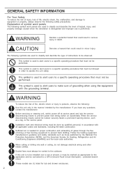
... used to alert users to a specific operating procedure that must be marked as a tag, to the service panel. When the service disconnecting means cannot be locked, securely fasten a prominent warning device, such as appropriate for Heating, Refrigeration and Air Conditioning Engineers (ASHRAE) and the local code authorities. When cutting or drilling into wall or ceiling, do not damage electrical...
... used to alert users to a specific operating procedure that must be marked as a tag, to the service panel. When the service disconnecting means cannot be locked, securely fasten a prominent warning device, such as appropriate for Heating, Refrigeration and Air Conditioning Engineers (ASHRAE) and the local code authorities. When cutting or drilling into wall or ceiling, do not damage electrical...
FV08VSL3 User Guide
Page 3
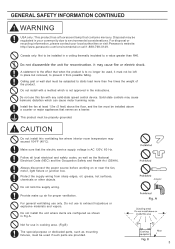
... dedicated parts, such as shown in the instructions. This product must be properly grounded. Do not use this ventilating fan where interior room temperature may be left in your local authorities or visit Panasonic website: http://www.panasonic.com/environmental or call 1-888-769-0149. Disposal may exceed 104°F (40°C). CAUTION Do not install this...
... dedicated parts, such as shown in the instructions. This product must be properly grounded. Do not use this ventilating fan where interior room temperature may be left in your local authorities or visit Panasonic website: http://www.panasonic.com/environmental or call 1-888-769-0149. Disposal may exceed 104°F (40°C). CAUTION Do not install this...
FV08VSL3 User Guide
Page 4
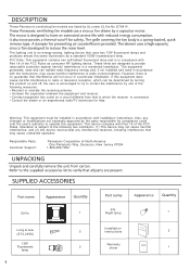
... with Part 18 of North America One Panasonic Way, Secaucus, New Jersey 07094 1-866-292-7292 Grille 4W 1 Night lamp 1 Long screw Installation 5 instructions 2 (ST4.2X30) 13W Warranty Fluorescent 2 sheet 1 lamp 4 Responsible Party: Customer Support: Panasonic Corporation of the FCC Rules. The lighting unit is subject to radio communications. This equipment generates, uses and can be installed in a particular installation...
... with Part 18 of North America One Panasonic Way, Secaucus, New Jersey 07094 1-866-292-7292 Grille 4W 1 Night lamp 1 Long screw Installation 5 instructions 2 (ST4.2X30) 13W Warranty Fluorescent 2 sheet 1 lamp 4 Responsible Party: Customer Support: Panasonic Corporation of the FCC Rules. The lighting unit is subject to radio communications. This equipment generates, uses and can be installed in a particular installation...

FV08VSL3 User Guide
Page 5
2 7/8 (73) 3 3/8 (85) 10 1/4 (260) 3 3/4 (94) Fan body Fluorescent lamp (Self-ballasted) Night lamp Junction box Black White Black Red White Capacitor White White Motor Black Black (114 CFuse in motor) Thermally - protected White Black Green Live Neutral Live (LIGHT) Power supply AC120V 60Hz Power supply AC120V 60Hz (N.LIGHT) Neutral Live Earth ground Power supply AC120V 60Hz 5
2 7/8 (73) 3 3/8 (85) 10 1/4 (260) 3 3/4 (94) Fan body Fluorescent lamp (Self-ballasted) Night lamp Junction box Black White Black Red White Capacitor White White Motor Black Black (114 CFuse in motor) Thermally - protected White Black Green Live Neutral Live (LIGHT) Power supply AC120V 60Hz Power supply AC120V 60Hz (N.LIGHT) Neutral Live Earth ground Power supply AC120V 60Hz 5
FV08VSL3 User Guide
Page 6
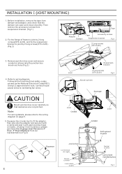
... steel Panasonic 4" Oval - 3" Round Reducer from suspension bracket. (Fig.1) 2. Remove junction box cover and secure conduit or stress relief to ventilating fan wires. Using UL approved wire nuts, connect house power wires to junction box knock-out hole.(Fig.3) 4. Light) Neutral to white Live to black (Light) 6 Joist Neutral to wiring diagram. Before installation, remove...
... steel Panasonic 4" Oval - 3" Round Reducer from suspension bracket. (Fig.1) 2. Remove junction box cover and secure conduit or stress relief to ventilating fan wires. Using UL approved wire nuts, connect house power wires to junction box knock-out hole.(Fig.3) 4. Light) Neutral to white Live to black (Light) 6 Joist Neutral to wiring diagram. Before installation, remove...
FV08VSL3 User Guide
Page 7
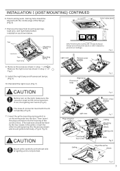
... installation as shown in step 1 of the Junction box. (The lead wire should be fixed by the four claws in step 2 of the flange. (Fig.4) 7. Then Insert the plug connector into the housing of Fig.5. Tape Lead wire Tape Night lamp 8. Reinstall the light cover.(Fig.7) CAUTION Before turn ...edge of Fig.5. 9. 6. Remove the light cover as shown and mount grille to prevent air leakage. Ceiling hole should be aligned with caulk or other mounting spring into the slot. Finish ceiling work .(Fig.8) The claw of lighting unit is on the light, make sure the conector insert at ...
... installation as shown in step 1 of the Junction box. (The lead wire should be fixed by the four claws in step 2 of the flange. (Fig.4) 7. Then Insert the plug connector into the housing of Fig.5. Tape Lead wire Tape Night lamp 8. Reinstall the light cover.(Fig.7) CAUTION Before turn ...edge of Fig.5. 9. 6. Remove the light cover as shown and mount grille to prevent air leakage. Ceiling hole should be aligned with caulk or other mounting spring into the slot. Finish ceiling work .(Fig.8) The claw of lighting unit is on the light, make sure the conector insert at ...
FV08VSL3 User Guide
Page 8
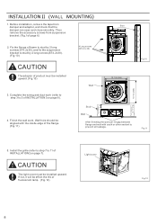
... 2 long screws(ST4.2x30), and fix the suspension bracket to 5 of product must be installed upward.(Fig.10) 3. Finish the wall work (refer to step 3 to stud by 2 long screws(ST4.2x30). (Fig.10) CAUTION The adaptor of INSTALLATION on page 7). CAUTION The light cover must be installed upward. WALL 1. Before installation, remove the tape from suspension...
... 2 long screws(ST4.2x30), and fix the suspension bracket to 5 of product must be installed upward.(Fig.10) 3. Finish the wall work (refer to step 3 to stud by 2 long screws(ST4.2x30). (Fig.10) CAUTION The adaptor of INSTALLATION on page 7). CAUTION The light cover must be installed upward. WALL 1. Before installation, remove the tape from suspension...
FV08VSL3 User Guide
Page 9
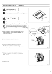
Remove grille by pulling down the mounting spring in the right side of "Panasonic" logo. Wipe dry with clean cloth.)(Fig.13) 2. The grille should be dry after cleaning. 3. WARNING CAUTION 1. Clean grille.(Don't put into water over Use non-abrasive kitchen detergent, wipe dry with clean cloth. (Fig.15) 5. Using a cloth dampened with kitchen detergent, remove any dirt from fan body using a vacuum cleaner. (Fig.14) 4. Replace grille. Fig.13 Fig.14 Fig.15 9 Remove dust and dirt from fan body.
Remove grille by pulling down the mounting spring in the right side of "Panasonic" logo. Wipe dry with clean cloth.)(Fig.13) 2. The grille should be dry after cleaning. 3. WARNING CAUTION 1. Clean grille.(Don't put into water over Use non-abrasive kitchen detergent, wipe dry with clean cloth. (Fig.15) 5. Using a cloth dampened with kitchen detergent, remove any dirt from fan body using a vacuum cleaner. (Fig.14) 4. Replace grille. Fig.13 Fig.14 Fig.15 9 Remove dust and dirt from fan body.
FV08VSL3 User Guide
Page 10
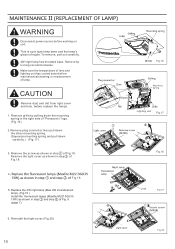
...Install the fluorescent lamps (Maxlite MLS13GU35 13W) as shown in the right side of Fig.18. 4 Fig.19. 5. Reinstall the light cover.(Fig.20) 10 Fig.16 Mounting spring Lighting unit Fig.17 Fig.18 Lens Fig.19 Fig.20 Remove the screw as shown in step 2 of "Panasonic... mounting spring in step 1 of Fig. 6 (page 7). 6. CAUTION Remove dust and dirt from light cover and lens, before maintenance(cleaning) or replacement of lens and lighting unit has cooled down carefully.) (Fig.17) 3. Make sure the temperature of lamp. WARNING Disconnect power source before working on unit.
...Install the fluorescent lamps (Maxlite MLS13GU35 13W) as shown in the right side of Fig.18. 4 Fig.19. 5. Reinstall the light cover.(Fig.20) 10 Fig.16 Mounting spring Lighting unit Fig.17 Fig.18 Lens Fig.19 Fig.20 Remove the screw as shown in step 2 of "Panasonic... mounting spring in step 1 of Fig. 6 (page 7). 6. CAUTION Remove dust and dirt from light cover and lens, before maintenance(cleaning) or replacement of lens and lighting unit has cooled down carefully.) (Fig.17) 3. Make sure the temperature of lamp. WARNING Disconnect power source before working on unit.
FV08VSL3 User Guide
Page 11
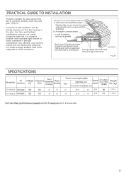
... lamps do not create excessive heat that is a common problem with recessed light fixtures or some competitor's fan/light combination. Our fans and fan/light combination units do not create enough ambient heat to be subjected to minimize building heat loss and gain. (Fig.21) Loose fill or batt insulation can be placed directly over the fan housing...
... lamps do not create excessive heat that is a common problem with recessed light fixtures or some competitor's fan/light combination. Our fans and fan/light combination units do not create enough ambient heat to be subjected to minimize building heat loss and gain. (Fig.21) Loose fill or batt insulation can be placed directly over the fan housing...

