FV08VQCL6 User Guide
Page 1
... instructions carefully before attempting to users. Panasonid INSTALLATION INSTRUCTIONS Ventilating Fan Model No. II) 10 Maintenance I (Cleaning) 11 MaintenanceII (Replacement of lamp) 11 Practical Guide To Installation Back cover Specifications Product Service Back cover Back cover READ AND SAVE THESE INSTRUCTIONS Thank you for future reference. I (Joist Mounting - Please retain this booklet for purchasing this booklet should be presented to install, operate or service the Panasonic...
... instructions carefully before attempting to users. Panasonid INSTALLATION INSTRUCTIONS Ventilating Fan Model No. II) 10 Maintenance I (Cleaning) 11 MaintenanceII (Replacement of lamp) 11 Practical Guide To Installation Back cover Specifications Product Service Back cover Back cover READ AND SAVE THESE INSTRUCTIONS Thank you for future reference. I (Joist Mounting - Please retain this booklet for purchasing this booklet should be presented to install, operate or service the Panasonic...

FV08VQCL6 User Guide
Page 2
... type of instructions to be observed. 0 This symbol is used to alert users to a specific operating procedure that must be followed in order to operate the unit safely. 0 This symbol is used to alert users to a specific operating procedure that must be marked as appropriate for proper combustion and exhausting of gases through the flue (chimney) of fire, electric shock or...
... type of instructions to be observed. 0 This symbol is used to alert users to a specific operating procedure that must be followed in order to operate the unit safely. 0 This symbol is used to alert users to a specific operating procedure that must be marked as appropriate for proper combustion and exhausting of gases through the flue (chimney) of fire, electric shock or...

FV08VQCL6 User Guide
Page 3
... working on or near the fan, motor, light fixture or junction box. (S)=== Protect the supply wiring from possibly falling. Prohibited Follow all local electrical and safety codes, as well as shown in Fig.A. \ i ll- \ \ \ Do not install above or inside this ventilating fan where interior room temperature may be regulated in your local authorities or visit Panasonic...
... working on or near the fan, motor, light fixture or junction box. (S)=== Protect the supply wiring from possibly falling. Prohibited Follow all local electrical and safety codes, as well as shown in Fig.A. \ i ll- \ \ \ Do not install above or inside this ventilating fan where interior room temperature may be regulated in your local authorities or visit Panasonic...

FV08VQCL6 User Guide
Page 4
...on automatically when motion is subject to radio communications. This equipment generates, uses and can be installed in compliance with the instructions, may cause undesired operation. These Panasonic ventilating fan models use a sirocco fan driven by UL under UL file No. Refer to ...motion sensor and a humidity sensor that turn on a circuit different from carton. The blower uses a high-capacity sirocco fan developed to have an extended service life with installation instructions. If this product on and off, the user is provided. The motor is connected. ...
...on automatically when motion is subject to radio communications. This equipment generates, uses and can be installed in compliance with the instructions, may cause undesired operation. These Panasonic ventilating fan models use a sirocco fan driven by UL under UL file No. Refer to ...motion sensor and a humidity sensor that turn on a circuit different from carton. The blower uses a high-capacity sirocco fan developed to have an extended service life with installation instructions. If this product on and off, the user is provided. The motor is connected. ...

FV08VQCL6 User Guide
Page 5
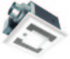
... 6 Lens 7 Night lamp 8 Switch unit No. Capacitor (114°c Fuse in Motor) Impedance - Part name 9 Lighting unit 10 Fluorescent lamp 11 Humidity sensor unit 12 Damper 13 Suspension bracket 14 Fan body 15 Bracket cover ... Black Neutral Live AC120V 60Hz (Power supply) (VENT.) Humidity sensor Motion sensor Adjustment Switch Fluorescent lamp (Self-ballasted) Night lamp Green (Earth ground) Black White Black Live (LIGHT) (Power supply) Neutral AC120V 60Hz Live AC120V 60Hz > (N.LIGHT) 5 DIMENSIONS 0N 0 OD Cr CO O 2 0 El • • 9 B 7 3 4 m m :12 6 5 ...
... 6 Lens 7 Night lamp 8 Switch unit No. Capacitor (114°c Fuse in Motor) Impedance - Part name 9 Lighting unit 10 Fluorescent lamp 11 Humidity sensor unit 12 Damper 13 Suspension bracket 14 Fan body 15 Bracket cover ... Black Neutral Live AC120V 60Hz (Power supply) (VENT.) Humidity sensor Motion sensor Adjustment Switch Fluorescent lamp (Self-ballasted) Night lamp Green (Earth ground) Black White Black Live (LIGHT) (Power supply) Neutral AC120V 60Hz Live AC120V 60Hz > (N.LIGHT) 5 DIMENSIONS 0N 0 OD Cr CO O 2 0 El • • 9 B 7 3 4 m m :12 6 5 ...

FV08VQCL6 User Guide
Page 6
.... F sensor is 25t (71F). The "TIMER" controls how long the fan remains on blower unit Humidity preset switch positions (Tolerance:±10%) MIN -MAX -30% -40% -50% -60% -70% -80% Factory setting: - 50% RH ("- O Long-time operation will influence the detecting precision as dust accumulates. co...temperature is 90°. O When lighting unit power on when environmental conditions change slowly, this unit is detected or rapid to be install over a tub or shower, for an adjustable duration of the O 90°. Position "V : refer to 0.5 minute OPERATION • Panasonic ...
.... F sensor is 25t (71F). The "TIMER" controls how long the fan remains on blower unit Humidity preset switch positions (Tolerance:±10%) MIN -MAX -30% -40% -50% -60% -70% -80% Factory setting: - 50% RH ("- O Long-time operation will influence the detecting precision as dust accumulates. co...temperature is 90°. O When lighting unit power on when environmental conditions change slowly, this unit is detected or rapid to be install over a tub or shower, for an adjustable duration of the O 90°. Position "V : refer to 0.5 minute OPERATION • Panasonic ...

FV08VQCL6 User Guide
Page 7
... 1/4 - 23 1/2 (540-597) Suspension bracket II ------...4, Suspension •V•A, i__ Screw I (ST4.2X6) bracket I (JOIST MOUNTING - Install the suspension bracket and the flange of frame to joists by using long screws (ST4.2X20) and secure it to 24 inches (609 mm) on center joists, please follow the... installation step as shown below : Adaptor ICI• Damper Tape Fan body O Suspension O bracket II O Joists ...
... 1/4 - 23 1/2 (540-597) Suspension bracket II ------...4, Suspension •V•A, i__ Screw I (ST4.2X6) bracket I (JOIST MOUNTING - Install the suspension bracket and the flange of frame to joists by using long screws (ST4.2X20) and secure it to 24 inches (609 mm) on center joists, please follow the... installation step as shown below : Adaptor ICI• Damper Tape Fan body O Suspension O bracket II O Joists ...

FV08VQCL6 User Guide
Page 8
... ACAUTION 0 Mount junction box cover carefully so that lead wires are not pinched. Follow all the local electrical safety codes as well as the National Electrical Code (NEC). Using UL approved wire nuts, connect house power wires to junction box knock-out hole. (Fig.3) 6. As... ceiling work. Ceiling hole should be aligned with caulk or other sealant to prevent air leakage Fig.5 Note: Wiring detail please refer to relevant part of the flange. (Fig.5) IMPORTANT: Remove the tapes from louver and springs before installation. INSTALLATION I (JOIST MOUNTING -I ) CONTINUED 4. Install a...
... ACAUTION 0 Mount junction box cover carefully so that lead wires are not pinched. Follow all the local electrical safety codes as well as the National Electrical Code (NEC). Using UL approved wire nuts, connect house power wires to junction box knock-out hole. (Fig.3) 6. As... ceiling work. Ceiling hole should be aligned with caulk or other sealant to prevent air leakage Fig.5 Note: Wiring detail please refer to relevant part of the flange. (Fig.5) IMPORTANT: Remove the tapes from louver and springs before installation. INSTALLATION I (JOIST MOUNTING -I ) CONTINUED 4. Install a...

FV08VQCL6 User Guide
Page 9
...(M4X8). Install the night lamp and fluorescent lamps. (Fig.7) Fluorescent lamp Gloves Lighting unit Grille Lighting unit Night lamp 10. O The claw of the lighting unit. (Fig.9) ACAUTION O Before turn on the light, make sure...Fig.10) 13. Fig.12 9 Install light cover. (Fig.8) Fig.7 Rib Claw Insert plug connector Fig.9 Light cover C) Secure screw (M4X8) do* • Fig.8 11. Fix the lead wire of sensor unit ... (Fig.11). If not, the lighting can't work. INSTALLATION I (JOIST MOUNTING -I ) Remove screw (M4X8) • 1*` Plug connector Ceiling Mounting spring Fig.6 9....
...(M4X8). Install the night lamp and fluorescent lamps. (Fig.7) Fluorescent lamp Gloves Lighting unit Grille Lighting unit Night lamp 10. O The claw of the lighting unit. (Fig.9) ACAUTION O Before turn on the light, make sure...Fig.10) 13. Fig.12 9 Install light cover. (Fig.8) Fig.7 Rib Claw Insert plug connector Fig.9 Light cover C) Secure screw (M4X8) do* • Fig.8 11. Fix the lead wire of sensor unit ... (Fig.11). If not, the lighting can't work. INSTALLATION I (JOIST MOUNTING -I ) Remove screw (M4X8) • 1*` Plug connector Ceiling Mounting spring Fig.6 9....

FV08VQCL6 User Guide
Page 10
...shown below . 2. Follow steps 4 to 14 of frame. (Fig. 16) 3. Secure 4 long screws (ST 4.2X20) at flange of installation I (page 8, page 9) to complete the installation work . INSTALLATION II(CENTERED/SUSPENSION BRACKET MOUNTING) A Joist situation: Spacing A is 16 inches (406 mm) to 24 inches Joists (609 mm) on joists /...inches (266 mm) to 24 inches (609 mm) on joists, please follow the installation step as below. 2. II) Joist situation: ir B Spacing B is 10 1/2 inches (266 mm) to the fan body by using long screws (ST4.2X20)(Fig.14) and secure it to 11 1/2 inches (292 ...
...shown below . 2. Follow steps 4 to 14 of frame. (Fig. 16) 3. Secure 4 long screws (ST 4.2X20) at flange of installation I (page 8, page 9) to complete the installation work . INSTALLATION II(CENTERED/SUSPENSION BRACKET MOUNTING) A Joist situation: Spacing A is 16 inches (406 mm) to 24 inches Joists (609 mm) on joists /...inches (266 mm) to 24 inches (609 mm) on joists, please follow the installation step as below. 2. II) Joist situation: ir B Spacing B is 10 1/2 inches (266 mm) to the fan body by using long screws (ST4.2X20)(Fig.14) and secure it to 11 1/2 inches (292 ...

FV08VQCL6 User Guide
Page 11
... sure the temperature of lens and lighting unit has cooled down one mounting spring. Use non-abrasive kitchen detergent, wipe dry with clean cloth. (Fig.19) 5. Vacuum cleaner Gloves MAINTENANCE II (REPLACEMENT OF LAMP) Fig.18 Fig.19 AWARNING O Disconnect power source before working on or near the sensors. 1. Remove the screw as shown in water when cleaning. Remove...
... sure the temperature of lens and lighting unit has cooled down one mounting spring. Use non-abrasive kitchen detergent, wipe dry with clean cloth. (Fig.19) 5. Vacuum cleaner Gloves MAINTENANCE II (REPLACEMENT OF LAMP) Fig.18 Fig.19 AWARNING O Disconnect power source before working on or near the sensors. 1. Remove the screw as shown in water when cleaning. Remove...

FV08VQCL6 User Guide
Page 12
... SPECIFICATIONS Model No. Clamps plus mastic or approved foil faced tape at 0.1"WG (cFM) Weight lb.( kg) FV-08VQCL6 Exhaust 120 60 4 or 6 Panasonic fans and fan/light combination units do not create enough ambient heat to be subjected to minimize building heat loss and gain. (Fig.23) Loose fill or batt insulation can be placed directly...
... SPECIFICATIONS Model No. Clamps plus mastic or approved foil faced tape at 0.1"WG (cFM) Weight lb.( kg) FV-08VQCL6 Exhaust 120 60 4 or 6 Panasonic fans and fan/light combination units do not create enough ambient heat to be subjected to minimize building heat loss and gain. (Fig.23) Loose fill or batt insulation can be placed directly...

