FV08VQL6 User Guide
Page 1
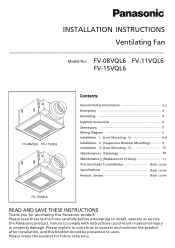
FV-08VQL6 FV-11VQL6 FV-15VQL6 FV-08VQL6 FV-11VQL6 FV-15VQL6 Thank you for purchasing this Panasonic product. 2-3 5 5 6-8 11 Back cover Back cover Back cover
FV-08VQL6 FV-11VQL6 FV-15VQL6 FV-08VQL6 FV-11VQL6 FV-15VQL6 Thank you for purchasing this Panasonic product. 2-3 5 5 6-8 11 Back cover Back cover Back cover

FV08VQL6 User Guide
Page 2
... as a tag, to the service panel. Before servicing or cleaning unit, switch power off at service panel and lock the service disconnecting means to the outdoors. These models are UL listed for tub and shower enclosures. 2 This symbol is used to alert users to a specific operating procedure that must be done by the manufacturer. Installation work and electrical wiring must be performed. When...
... as a tag, to the service panel. Before servicing or cleaning unit, switch power off at service panel and lock the service disconnecting means to the outdoors. These models are UL listed for tub and shower enclosures. 2 This symbol is used to alert users to a specific operating procedure that must be done by the manufacturer. Installation work and electrical wiring must be performed. When...

FV08VQL6 User Guide
Page 3
...use to exhaust hazardous or explosive materials and vapors. Not for use in your local authorities or visit Panasonic website: http://www.panasonic.com/environmental or call 1-888-769-0149. Adaptor 3 Disposal may cause fire or electric shock. Protect the supply wiring from sharp edges, oil, grease, hot...grounded. This product must be installed in the instrucions. Always disconnect the power source before working on or near the fan, motor, light fixture or junction box. CAUTION Do not install this ventilating fan where interior room temperature may exceed 104°F(40&#...
...use to exhaust hazardous or explosive materials and vapors. Not for use in your local authorities or visit Panasonic website: http://www.panasonic.com/environmental or call 1-888-769-0149. Adaptor 3 Disposal may cause fire or electric shock. Protect the supply wiring from sharp edges, oil, grease, hot...grounded. This product must be installed in the instrucions. Always disconnect the power source before working on or near the fan, motor, light fixture or junction box. CAUTION Do not install this ventilating fan where interior room temperature may exceed 104°F(40&#...

FV08VQL6 User Guide
Page 4
... and, if not installed and used in compliance with the instructions, may cause undesired operation. Operation is subject to the following measures: • Reorient or relocate the receiving antenna. • Increase the separation between the equipment and receiver. • Connect equipment into outlet on and off, the user is in accordance with Part 18 of the FCC...
... and, if not installed and used in compliance with the instructions, may cause undesired operation. Operation is subject to the following measures: • Reorient or relocate the receiving antenna. • Increase the separation between the equipment and receiver. • Connect equipment into outlet on and off, the user is in accordance with Part 18 of the FCC...

FV08VQL6 User Guide
Page 5
FV-08VQL6 FV-11VQL6 FV-15VQL6 10 1/4 (260) 4 3/5 (116) 4 3/5 (116) 10 1/4 (260) Fan body Wiring diagram Junction box Fluorescent lamp (Self-ballasted) Night lamp Black Live White Neutral Black Live (LIGHT) (N.LIGHT) Capacitor Motor (Fuse in motor) Fuse type: FV-08VQL6: (114 c) Impedance - protected FV-15VQL6: (134 c) Thermally protected (Power supply) AC120V 60Hz White Black Green Neutral Live (VENT.) (Earth ground) Earth ground 5 protected FV-11VQL6: (114 c) Impedance -
FV-08VQL6 FV-11VQL6 FV-15VQL6 10 1/4 (260) 4 3/5 (116) 4 3/5 (116) 10 1/4 (260) Fan body Wiring diagram Junction box Fluorescent lamp (Self-ballasted) Night lamp Black Live White Neutral Black Live (LIGHT) (N.LIGHT) Capacitor Motor (Fuse in motor) Fuse type: FV-08VQL6: (114 c) Impedance - protected FV-15VQL6: (134 c) Thermally protected (Power supply) AC120V 60Hz White Black Green Neutral Live (VENT.) (Earth ground) Earth ground 5 protected FV-11VQL6: (114 c) Impedance -

FV08VQL6 User Guide
Page 7
6. Remove screw (M4X8). Remove light cover. (Fig.6) Fig.5 Fig.6 7 Refer to wiring diagram. (Wiring detail please refer to the wiring diagram on page 5.) CAUTION (Night lamp) Fig.3 Fig.4 8.
6. Remove screw (M4X8). Remove light cover. (Fig.6) Fig.5 Fig.6 7 Refer to wiring diagram. (Wiring detail please refer to the wiring diagram on page 5.) CAUTION (Night lamp) Fig.3 Fig.4 8.

FV08VQL6 User Guide
Page 8
Install the night lamp and fluorescent lamps. (Fig.7) 3 10. Install light cover. (Fig.8) CAUTION (Fig.9) 11. (Fig.9) 12. (Fig.9, Fig.10) CAUTION 8 Fig.7 Secure screw (M4X8) Fig.8 Fig.9 Fig.10 9.
Install the night lamp and fluorescent lamps. (Fig.7) 3 10. Install light cover. (Fig.8) CAUTION (Fig.9) 11. (Fig.9) 12. (Fig.9, Fig.10) CAUTION 8 Fig.7 Secure screw (M4X8) Fig.8 Fig.9 Fig.10 9.

FV08VQL6 User Guide
Page 10
Use non-abrasive kitchen detergent, wipe dry with clean cloth) (Fig.15) (Fig.16) 10 (Fig.17) Fig.14 Fig.15 Fig.16 Fig.17 (Fig.14) 12 (page 7, page 8) WARNING CAUTION 1.Clean grille. (Don't put into hot water.
Use non-abrasive kitchen detergent, wipe dry with clean cloth) (Fig.15) (Fig.16) 10 (Fig.17) Fig.14 Fig.15 Fig.16 Fig.17 (Fig.14) 12 (page 7, page 8) WARNING CAUTION 1.Clean grille. (Don't put into hot water.

FV08VQL6 User Guide
Page 11
Fig.18 (Fig.18) Fig.19 . Replace the 4W night lamp. (Fig. 20) Install the fluorescent lamps (Maxlite MLS13GU35 13W) as shown in step 2 and step 3 of Fig.7 (page 8). 5. Replace the fluorescent lamps (Maxlite MLS13GU35 13W) as shown in step 1 and step 2 of page 8) Lens Fig.19 3 Fig.20 11 Install light cover. (Fig.8 of Fig.20. 4. WARNING ' CAUTION Remove dust and dirt from light cover and lens, before replace the lamps. Fig.19. 3.
Fig.18 (Fig.18) Fig.19 . Replace the 4W night lamp. (Fig. 20) Install the fluorescent lamps (Maxlite MLS13GU35 13W) as shown in step 2 and step 3 of Fig.7 (page 8). 5. Replace the fluorescent lamps (Maxlite MLS13GU35 13W) as shown in step 1 and step 2 of page 8) Lens Fig.19 3 Fig.20 11 Install light cover. (Fig.8 of Fig.20. 4. WARNING ' CAUTION Remove dust and dirt from light cover and lens, before replace the lamps. Fig.19. 3.

