
FV40VQ3 User Guide
Page 1
Please retain this Panasonic product. Please read these instructions carefully before attempting to users. FV-20VQ3 FV-30VQ3 FV-40VQ4 Table of Contents Supplied Accessories Description Wiring Diagram Dimensions .... Please explain to users how to operate and maintain the product after installation, and this booklet should be presented to install, operate or service the Panasonic product. Failure to installation Product Service 2 2 2 3 3 3 4 5 6 7 7-Back cover Back cover Back cover READ AND SAVE THESE INSTRUCTIONS Thank you for purchasing this booklet for future...
Please retain this Panasonic product. Please read these instructions carefully before attempting to users. FV-20VQ3 FV-30VQ3 FV-40VQ4 Table of Contents Supplied Accessories Description Wiring Diagram Dimensions .... Please explain to users how to operate and maintain the product after installation, and this booklet should be presented to install, operate or service the Panasonic product. Failure to installation Product Service 2 2 2 3 3 3 4 5 6 7 7-Back cover Back cover Back cover READ AND SAVE THESE INSTRUCTIONS Thank you for purchasing this booklet for future...
FV40VQ3 User Guide
Page 2
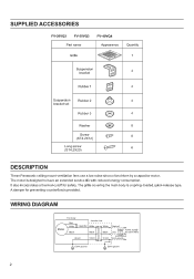
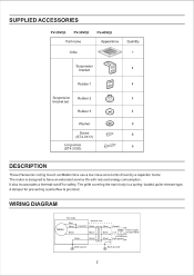
...Rubber 1 4 Suspension Rubber 2 4 bracket set Rubber 3 CD 4 Washer 0 8 Screw (ST4.2X12) 8 Long screw (ST4.2X20) L 3' 6 DESCRIPTION These Panasonic ceiling mount ventilation fans use a low noise sirocco fan driven by a capacitor motor. It also incorporates a thermal-cutoff for preventing counterflow is a spring- A damper for safety. Motor... Fan body Red White i Black Junction box Capacitor White White Black Black Green Green Green Neutral Switch Power supply...
...Rubber 1 4 Suspension Rubber 2 4 bracket set Rubber 3 CD 4 Washer 0 8 Screw (ST4.2X12) 8 Long screw (ST4.2X20) L 3' 6 DESCRIPTION These Panasonic ceiling mount ventilation fans use a low noise sirocco fan driven by a capacitor motor. It also incorporates a thermal-cutoff for preventing counterflow is a spring- A damper for safety. Motor... Fan body Red White i Black Junction box Capacitor White White Black Black Green Green Green Neutral Switch Power supply...
FV40VQ3 User Guide
Page 3
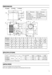
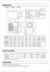
Part name ® Grille © Adapter 0 Junction box 0 Junction box cover 0 Fan body No. Air direction V Hz FV-20VQ3 FV-30VQ3 FV-40VQ4 Exhaust 120 60 Specifications are present. 3 FV-20VQ3 FV-30VQ3 FV-40VQ4 A 16 17 /...
Part name ® Grille © Adapter 0 Junction box 0 Junction box cover 0 Fan body No. Air direction V Hz FV-20VQ3 FV-30VQ3 FV-40VQ4 Exhaust 120 60 Specifications are present. 3 FV-20VQ3 FV-30VQ3 FV-40VQ4 A 16 17 /...
FV40VQ3 User Guide
Page 4
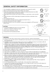
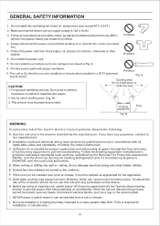
... it must be used , it can cause motor humming noise. M. Ceiling joist must be reached from being switched on or near the fan, motor or junction box. 5. This unit is not approved in a GFCI protected branch circuit. C. For general ventilating use over a tub...device. N. Follow all applicable codes and standards, including fire-rated construction. It may cause harmonic distortion which is UL listed for use this ventilating fan where air temperature may exceed 40°C (104°F). 2. A statement to no longer be left in cooking area. (Fig .B) \\ ...
... it must be used , it can cause motor humming noise. M. Ceiling joist must be reached from being switched on or near the fan, motor or junction box. 5. This unit is not approved in a GFCI protected branch circuit. C. For general ventilating use over a tub...device. N. Follow all applicable codes and standards, including fire-rated construction. It may cause harmonic distortion which is UL listed for use this ventilating fan where air temperature may exceed 40°C (104°F). 2. A statement to no longer be left in cooking area. (Fig .B) \\ ...
FV40VQ3 User Guide
Page 5
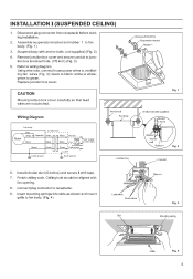
... Neutral Switch Power supply Live AC120V 60Hz Green Green (not included) Gre Earth ground>.. (•3 Earth ground Earth ground Fig. 1 Anchor bolt Fan body Junction box Anchor bolt (Not supplied) Rubber !!2 and 3 Washer " Anc or bolt Rubber 1 Fig. 2 Conduit 6. Replace junction box... cover carefully so that lead wires are not pinched. Refer to wiring diagram Using wire nuts, connect house power wires to ventilating fan wires (Fig. 3): black to white; INSTALLATION I (SUSPENDED CEILING) 1. Disconnect plug connector from receptacle before starting installation. 2. ...
... Neutral Switch Power supply Live AC120V 60Hz Green Green (not included) Gre Earth ground>.. (•3 Earth ground Earth ground Fig. 1 Anchor bolt Fan body Junction box Anchor bolt (Not supplied) Rubber !!2 and 3 Washer " Anc or bolt Rubber 1 Fig. 2 Conduit 6. Replace junction box... cover carefully so that lead wires are not pinched. Refer to wiring diagram Using wire nuts, connect house power wires to ventilating fan wires (Fig. 3): black to white; INSTALLATION I (SUSPENDED CEILING) 1. Disconnect plug connector from receptacle before starting installation. 2. ...
FV40VQ3 User Guide
Page 6
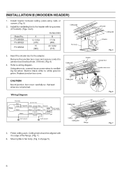
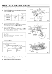
... joists using nails or screws. (Fig. 5) 2. FV-20VQ3 FV-30VQ3 FV-40VQ4 A 1213/32 (315) 15 (380) B 17 7/8 (454) 20 13/32 (518) fi Fan body 3. Insert the circular duct to white; white to the adapter. Finish ceiling work. Using wire nuts, connect house power wires to ventilating... fan wires: black to green. Mount grille to wiring diagram. green to black; Remove the junction box cover and secure conduit to the header with ...
... joists using nails or screws. (Fig. 5) 2. FV-20VQ3 FV-30VQ3 FV-40VQ4 A 1213/32 (315) 15 (380) B 17 7/8 (454) 20 13/32 (518) fi Fan body 3. Insert the circular duct to white; white to the adapter. Finish ceiling work. Using wire nuts, connect house power wires to ventilating... fan wires: black to green. Mount grille to wiring diagram. green to black; Remove the junction box cover and secure conduit to the header with ...
FV40VQ3 User Guide
Page 7
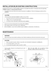
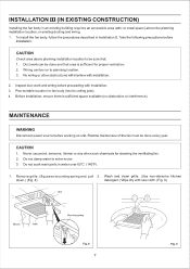
... (Use non-abrasive kitchen down.) (Fig. 8) detergent.) Wipe dry with installation. 2. INSTALLATION III (IN EXISTING CONSTRUCTION) Installing the fan body in an existing building requires an accessible area (attic or crawl space) above planning installation location to be sure that area is sufficient... space available (no obstruction or interference). No wiring or other such chemicals for cleaning the ventilating fan. 2. Before installation, ensure there is sufficient for proper ventilation. 2. Do not damp water to ceiling joist). 4. Take the ...
... (Use non-abrasive kitchen down.) (Fig. 8) detergent.) Wipe dry with installation. 2. INSTALLATION III (IN EXISTING CONSTRUCTION) Installing the fan body in an existing building requires an accessible area (attic or crawl space) above planning installation location to be sure that area is sufficient... space available (no obstruction or interference). No wiring or other such chemicals for cleaning the ventilating fan. 2. Before installation, ensure there is sufficient for proper ventilation. 2. Do not damp water to ceiling joist). 4. Take the ...
FV40VQ3 User Guide
Page 8
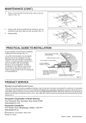
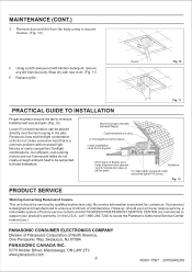
...insulation around the fan to locate the Panasonic Authorized Service Center nearest you.) Panasonic Corporation of North America One Panasonic Way, Secaucus, New Jersey 07094 www.panasonic.com Panasonic Canada Inc. 5770 Ambler Drive, Mississauga, Ontario L4W 2T3 www.panasonic.ca © Panasonic Corporation 2002-2012 ... a common problem with kitchen detergent, remove any dirt from fan body using a vacuum cleaner. (Fig. 10) 4. No service information is designed and manufactured to these limitations. Panasonic fans and fan/light combination units do not create enough ambient heat to be...
...insulation around the fan to locate the Panasonic Authorized Service Center nearest you.) Panasonic Corporation of North America One Panasonic Way, Secaucus, New Jersey 07094 www.panasonic.com Panasonic Canada Inc. 5770 Ambler Drive, Mississauga, Ontario L4W 2T3 www.panasonic.ca © Panasonic Corporation 2002-2012 ... a common problem with kitchen detergent, remove any dirt from fan body using a vacuum cleaner. (Fig. 10) 4. No service information is designed and manufactured to these limitations. Panasonic fans and fan/light combination units do not create enough ambient heat to be...
Installation Instructions
Page 1
... Header Installation) 6 InstallationIII (In Existing Construction) 7 Maintenance 7-8 Practical guide to comply with instructions could result in personal injury and/or property damage. INSTALLATION INSTRUCTIONS Ventilating Fan FV-20VQ3 FV-30VQ3 FV-40VQ3 Panasonid READ AND SAVE THESE INSTRUCTIONS. Please read these instructions carefully before attempting to install, operate or service the...
... Header Installation) 6 InstallationIII (In Existing Construction) 7 Maintenance 7-8 Practical guide to comply with instructions could result in personal injury and/or property damage. INSTALLATION INSTRUCTIONS Ventilating Fan FV-20VQ3 FV-30VQ3 FV-40VQ3 Panasonid READ AND SAVE THESE INSTRUCTIONS. Please read these instructions carefully before attempting to install, operate or service the...
Installation Instructions
Page 2
... service life with reduced energy consumption. Earth ground Earth ground 2 The motor is a spring- A damper for safety. WIRING DIAGRAM Motor Fan body Red White Black Junction box Capacitor White White Black Black Green Green Green Neutral Switch Power supply Live AC120V 60Hz (not included) Earth... az9 4 Rubber 1 4 103: Suspension Rubber 2 4 bracket set Rubber 3 0 4 Washer CD 8 Screw (ST4.2X12) 8 1) Long screw (ST4.2X20) El l' 6 DESCRIPTION These Panasonic ceiling mount ventilation fans use a low noise sirocco fan driven by a capacitor motor.
... service life with reduced energy consumption. Earth ground Earth ground 2 The motor is a spring- A damper for safety. WIRING DIAGRAM Motor Fan body Red White Black Junction box Capacitor White White Black Black Green Green Green Neutral Switch Power supply Live AC120V 60Hz (not included) Earth... az9 4 Rubber 1 4 103: Suspension Rubber 2 4 bracket set Rubber 3 0 4 Washer CD 8 Screw (ST4.2X12) 8 1) Long screw (ST4.2X20) El l' 6 DESCRIPTION These Panasonic ceiling mount ventilation fans use a low noise sirocco fan driven by a capacitor motor.
Installation Instructions
Page 3
... accessories list to verify that all parts are based on HVI standard. Part name 0 Grille © Adapter ® Junction box © Junction box cover © Fan body No. Power consumption (W) 43.5 66.5 119 Speed (rpm) 590 780 680 Air deliver at 0.1" WG (cfm) 190 290 380 Weight lb. (kg) 16.1 (7.3) 17...
... accessories list to verify that all parts are based on HVI standard. Part name 0 Grille © Adapter ® Junction box © Junction box cover © Fan body No. Power consumption (W) 43.5 66.5 119 Speed (rpm) 590 780 680 Air deliver at 0.1" WG (cfm) 190 290 380 Weight lb. (kg) 16.1 (7.3) 17...
Installation Instructions
Page 4
...and Air Conditioning Engineers (ASHRAE) and the local code authorities. When cutting or drilling into wall or ceiling, do not use this ventilating fan where air temperature may cause harmonic distortion which can be locked, securely fasten a prominent warning device, such as those published by the ... kink the power cord. 7. B WARNING: To reduce the risk of fuel burning equipment to prevent power from being switched on or near the fan, motor or junction box. 5. This unit is needed for use over a tub or shower, it can cause motor humming noise. Sufficient air ...
...and Air Conditioning Engineers (ASHRAE) and the local code authorities. When cutting or drilling into wall or ceiling, do not use this ventilating fan where air temperature may cause harmonic distortion which can be locked, securely fasten a prominent warning device, such as those published by the ... kink the power cord. 7. B WARNING: To reduce the risk of fuel burning equipment to prevent power from being switched on or near the fan, motor or junction box. 5. This unit is needed for use over a tub or shower, it can cause motor humming noise. Sufficient air ...

Installation Instructions
Page 5
... Slot Mounting spring f f Grille Fig. 4 5 Suspend body with fan opening. 8. Finish ceiling work. Insert mounting springs into slots as shown and mount grille to fan body. (Fig. 1) 3. Wiring Diagram Motor Fan body Red White Black Junction box Capacitor White White Black Black Neutral Switch...CEILING) 1. Refer to wiring diagram Using wire nuts, connect house power wires to ventilating fan wires (Fig. 3): black to black; Install circular duct (6 inches) and secure it with tape. 7. Anchor bolt Fan body Junction box Anchor bolt (Not supplied) II Rubber II and 3 Washer Anc or...
... Slot Mounting spring f f Grille Fig. 4 5 Suspend body with fan opening. 8. Finish ceiling work. Insert mounting springs into slots as shown and mount grille to fan body. (Fig. 1) 3. Wiring Diagram Motor Fan body Red White Black Junction box Capacitor White White Black Black Neutral Switch...CEILING) 1. Refer to wiring diagram Using wire nuts, connect house power wires to ventilating fan wires (Fig. 3): black to black; Install circular duct (6 inches) and secure it with tape. 7. Anchor bolt Fan body Junction box Anchor bolt (Not supplied) II Rubber II and 3 Washer Anc or...
Installation Instructions
Page 6
... Mount junction box cover carefully so that lead wires are not pinched. Mount grille to the header with the edge of page 5). 6 Install the ventilating fan to fan body. (Fig. 4 of the flange. (Fig. 7) 6. FV-20VQ3 FV-30VQ3 FV-40VQ3 A 12 13/32 (315) 15 (380) B 17 ...5 & 6) inches (mm) Model No. Refer to green. green to wiring diagram. Ceiling joist 6 Long screws (ST4.2X20) Wiring Diagram Motor Fan body Red White Black Junction box Capacitor White White Black Black Neutral SwitchPower supply Live ground_>.C120V 60Hz Green Green (not inducted) Greene Earth Earth...
... Mount junction box cover carefully so that lead wires are not pinched. Mount grille to the header with the edge of page 5). 6 Install the ventilating fan to fan body. (Fig. 4 of the flange. (Fig. 7) 6. FV-20VQ3 FV-30VQ3 FV-40VQ3 A 12 13/32 (315) 15 (380) B 17 ...5 & 6) inches (mm) Model No. Refer to green. green to wiring diagram. Ceiling joist 6 Long screws (ST4.2X20) Wiring Diagram Motor Fan body Red White Black Junction box Capacitor White White Black Black Neutral SwitchPower supply Live ground_>.C120V 60Hz Green Green (not inducted) Greene Earth Earth...
Installation Instructions
Page 7
...new cloth. (Fig. 9) Slot Gloves Grille Mounting spring Fig. 8 7 Fig. 9 INSTALLATION III (IN EXISTING CONSTRUCTION) Installing the fan body in an existing building requires an accessible area (attic or crawl space) above planning installation location to be run to planning location. ...precautions before installation. Wiring can be done every year. Before installation, ensure there is sufficient for proper ventilation. 2. To install the fan body, follow the procedures described in water over 60°C (140°F). 1. Do not soak resin parts in Installation II. ...
...new cloth. (Fig. 9) Slot Gloves Grille Mounting spring Fig. 8 7 Fig. 9 INSTALLATION III (IN EXISTING CONSTRUCTION) Installing the fan body in an existing building requires an accessible area (attic or crawl space) above planning installation location to be run to planning location. ...precautions before installation. Wiring can be done every year. Before installation, ensure there is sufficient for proper ventilation. 2. To install the fan body, follow the procedures described in water over 60°C (140°F). 1. Do not soak resin parts in Installation II. ...
Installation Instructions
Page 8
... be serviced by qualified technicians only. Replace grille. Short piece of North America, One Panasonic Way, Secaucus, NJ 07094 PANASONIC CANADA INC. 5770 Ambler Driver, Mississauga, ON L4W 2T3 www.panasonic.com 8 X0901-7067 20VQ34020G Wipe dry with backdraft flap(s). Panasonic fans and fan/light combination units do not create enough ambient heat to locate the...
... be serviced by qualified technicians only. Replace grille. Short piece of North America, One Panasonic Way, Secaucus, NJ 07094 PANASONIC CANADA INC. 5770 Ambler Driver, Mississauga, ON L4W 2T3 www.panasonic.com 8 X0901-7067 20VQ34020G Wipe dry with backdraft flap(s). Panasonic fans and fan/light combination units do not create enough ambient heat to locate the...
