Instruction Manual
Page 1
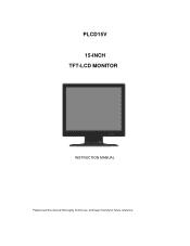
PLCD15V 15-INCH TFT-LCD MONITOR INSTRUCTION MANUAL Please read this manual thoroughly before use, and keep it handy for future reference.
PLCD15V 15-INCH TFT-LCD MONITOR INSTRUCTION MANUAL Please read this manual thoroughly before use, and keep it handy for future reference.
Instruction Manual
Page 2
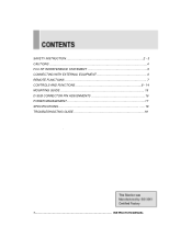
SAFETY INSTRUCTION 2 - 3 CAUTIONS ...4 FCC RF INTERFERENCE STATEMENT 5 CONNECTING WITH EXTERNAL EQUIPMENT 6 REMOTE FUNCTIONS 7 CONTROLS AND FUNCTIONS 8 - 14 MOUNTING GUIDE 15 D-SUB CONNECTOR PIN ASSIGNMENTS 16 POWER MANAGEMENT 17 SPECIFICATIONS 18 TROUBLESHOOTING GUIDE 19 . 1 INSTRUCTION MANUAL
SAFETY INSTRUCTION 2 - 3 CAUTIONS ...4 FCC RF INTERFERENCE STATEMENT 5 CONNECTING WITH EXTERNAL EQUIPMENT 6 REMOTE FUNCTIONS 7 CONTROLS AND FUNCTIONS 8 - 14 MOUNTING GUIDE 15 D-SUB CONNECTOR PIN ASSIGNMENTS 16 POWER MANAGEMENT 17 SPECIFICATIONS 18 TROUBLESHOOTING GUIDE 19 . 1 INSTRUCTION MANUAL
Instruction Manual
Page 3
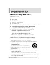
Install in any way, such as radiators, heat registers,stoves, or other . Only use caution when moving .. Use only with the cart, stand, tripod, bracket or table specified by the manufacturer. 12. Follow all warnings. 4. The wide ...plug. Read these Instructions. 3. the cart/apparatus combination to avoid injury from the apparatus. 11. INSTRUCTION MANUAL 2 Heed all instructions. 5. Refer all servicing to rain or moisture does not operate normally or has been dropped. Keep these instructions. 2. Do not block any heat sources such as power-supply cord or plug...
Install in any way, such as radiators, heat registers,stoves, or other . Only use caution when moving .. Use only with the cart, stand, tripod, bracket or table specified by the manufacturer. 12. Follow all warnings. 4. The wide ...plug. Read these Instructions. 3. the cart/apparatus combination to avoid injury from the apparatus. 11. INSTRUCTION MANUAL 2 Heed all instructions. 5. Refer all servicing to rain or moisture does not operate normally or has been dropped. Keep these instructions. 2. Do not block any heat sources such as power-supply cord or plug...
Instruction Manual
Page 4
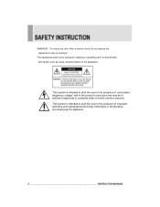
... may be of sufficient magnitude to constitute arisk of electric shock to the presence of important operating and maintenance(servicing) instructions in the literature accompanying the appliance. 3 INSTRUCTION MANUAL This symbol is intended to alert the user to rain or moisture." "WARNING - To reduce the risk of fire or electric shock, do not expose the...
... may be of sufficient magnitude to constitute arisk of electric shock to the presence of important operating and maintenance(servicing) instructions in the literature accompanying the appliance. 3 INSTRUCTION MANUAL This symbol is intended to alert the user to rain or moisture." "WARNING - To reduce the risk of fire or electric shock, do not expose the...
Instruction Manual
Page 5
CAUTIONk The power supply cord is used in direct sunshine or near the equipment and is located/installed near a heating appliance. ▶ TO ELIMINATE EYE FATIGUE Do not use the unit against a bright back ground and where sunlight or other light sources will shine directly on the monitor. ▶ BE CAREFUL OF HEAVY OBJECT Neither the monitor itself nor any other heavy...
CAUTIONk The power supply cord is used in direct sunshine or near the equipment and is located/installed near a heating appliance. ▶ TO ELIMINATE EYE FATIGUE Do not use the unit against a bright back ground and where sunlight or other light sources will shine directly on the monitor. ▶ BE CAREFUL OF HEAVY OBJECT Neither the monitor itself nor any other heavy...
Instruction Manual
Page 6
...frequency energy and, if not installed and used . Only shielded interface cable should be determined by turning the equipment off and on a circuit different from digital apparatus set out in a residential installation. If this equipment does cause harmful interference to radio or television reception which the receiver is connected... designed to Part 15 of the FCC Rules. Finally, any changes or modifications to the equipment by the user not expressly approved by one or more of communications. 5 INSTRUCTION MANUAL Connect the equipment into an outlet on , the user is no ...
...frequency energy and, if not installed and used . Only shielded interface cable should be determined by turning the equipment off and on a circuit different from digital apparatus set out in a residential installation. If this equipment does cause harmful interference to radio or television reception which the receiver is connected... designed to Part 15 of the FCC Rules. Finally, any changes or modifications to the equipment by the user not expressly approved by one or more of communications. 5 INSTRUCTION MANUAL Connect the equipment into an outlet on , the user is no ...
Instruction Manual
Page 7
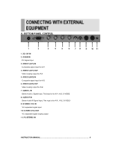
... STEREO IN 78 9 10 11 INSTRUCTION MANUAL 6 BOTTOM PANEL CONTROL 1 2 3 4 5 6 1. VIDEO 1(AV1) IN Composite signal Input for AV1 5. VIDEO 2(AV2) IN Composite signal Input for AV2 7. S-VIDEO (Y/C) OUT Y/C separated signal looping output 11. D-SUB IN PC Signal Input 3. AUDIO R IN Stereo Audio R Signal Input, This input is for AV1, AV2, S-VIDEO 9. S-VIDEO (Y/C) IN Y/C separated signal input 10. DC 12V IN 2. AUDIO L IN Stereo Audio L Signal Input, This input is for AV1, AV2, S-VIDEO 8. VIDEO 2(AV2) OUT Video looping output for AV2 6. A.
... STEREO IN 78 9 10 11 INSTRUCTION MANUAL 6 BOTTOM PANEL CONTROL 1 2 3 4 5 6 1. VIDEO 1(AV1) IN Composite signal Input for AV1 5. VIDEO 2(AV2) IN Composite signal Input for AV2 7. S-VIDEO (Y/C) OUT Y/C separated signal looping output 11. D-SUB IN PC Signal Input 3. AUDIO R IN Stereo Audio R Signal Input, This input is for AV1, AV2, S-VIDEO 9. S-VIDEO (Y/C) IN Y/C separated signal input 10. DC 12V IN 2. AUDIO L IN Stereo Audio L Signal Input, This input is for AV1, AV2, S-VIDEO 8. VIDEO 2(AV2) OUT Video looping output for AV2 6. A.
Instruction Manual
Page 8
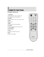
POWER( ) Turns the power ON or OFF. MUTE Mute the sound. 4. SOURCE Select pc or video( PC / AV1 / AV2 / S-Video ) sources. 3. VOL( ) Increases or decreases the level of audio volume. 6. MENU Activates and exits the On Screen Display. 5. EXIT Exit the On Screen Display. 7 INSTRUCTION MANUAL REMOTE CONTROLLER 1. AUTO Auto geometry adjustment in PC Source. 8. UP/DOWN( ) Move to OSD menu. 7. B. There will be a few seconds delay before the display appears. 2.
POWER( ) Turns the power ON or OFF. MUTE Mute the sound. 4. SOURCE Select pc or video( PC / AV1 / AV2 / S-Video ) sources. 3. VOL( ) Increases or decreases the level of audio volume. 6. MENU Activates and exits the On Screen Display. 5. EXIT Exit the On Screen Display. 7 INSTRUCTION MANUAL REMOTE CONTROLLER 1. AUTO Auto geometry adjustment in PC Source. 8. UP/DOWN( ) Move to OSD menu. 7. B. There will be a few seconds delay before the display appears. 2.
Instruction Manual
Page 9
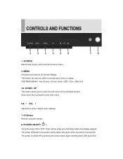
... turned off by pressing the power switch again and the power LED goes Red. This button can also be a few seconds delay before the display appears. OSD MENU(MAIN) : Input Source, Screen, Audio, OSD, Color, Utility, Exit. 3/4. MENU Activates and exits the On Screen Display. There will be used to move the previous menu. 2. The power is pressed on the main menu. 5/6. ◀ VOL ▶ Adjust the volume / Adjust menu settings. 7. SOURCE Select input source, and move previous menu or status. IR Sensor Remote controller...
... turned off by pressing the power switch again and the power LED goes Red. This button can also be a few seconds delay before the display appears. OSD MENU(MAIN) : Input Source, Screen, Audio, OSD, Color, Utility, Exit. 3/4. MENU Activates and exits the On Screen Display. There will be used to move the previous menu. 2. The power is pressed on the main menu. 5/6. ◀ VOL ▶ Adjust the volume / Adjust menu settings. 7. SOURCE Select input source, and move previous menu or status. IR Sensor Remote controller...

Instruction Manual
Page 10
SELF-TEST DISPLAY When there is no connection at PC, the On Screen Display will show for 3 seconds. 2. OSD MENU DESCRIPTION : Input Source Select PC or AV1, SVIDEO. INSTRUCTION MANUAL 8 1.
SELF-TEST DISPLAY When there is no connection at PC, the On Screen Display will show for 3 seconds. 2. OSD MENU DESCRIPTION : Input Source Select PC or AV1, SVIDEO. INSTRUCTION MANUAL 8 1.
Instruction Manual
Page 11
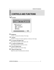
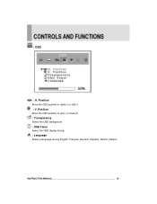
position (PC Mode Only) Move image horizontally on screen up or down. : Clock (PC Mode Only) Adjust the vertical noise of screen image. : Phase (PC Mode Only) Adjust the number of the image. : H. 9 INSTRUCTION MANUAL : Screen : Brightness Increase or decrease the intensity of the image. : Contrast Increase or decrease the intensity (lightness or dimness) of horizontal picture elements. INSTRUCTION MANUAL 10 position (PC Mode Only) Move image vertically on screen right or left. : V.
position (PC Mode Only) Move image horizontally on screen up or down. : Clock (PC Mode Only) Adjust the vertical noise of screen image. : Phase (PC Mode Only) Adjust the number of the image. : H. 9 INSTRUCTION MANUAL : Screen : Brightness Increase or decrease the intensity of the image. : Contrast Increase or decrease the intensity (lightness or dimness) of horizontal picture elements. INSTRUCTION MANUAL 10 position (PC Mode Only) Move image vertically on screen right or left. : V.
Instruction Manual
Page 12
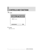
: Audio : Volume Adjust audio volume. 11 INSTRUCTION MANUAL
: Audio : Volume Adjust audio volume. 11 INSTRUCTION MANUAL
Instruction Manual
Page 13
Position Move the OSD position to right(▶) or left(◀). : V. Position Move the OSD position to up(▶) or down(◀). : Transparency Select the OSD background. : OSD Timer Select the OSD display timing. : Language Select a language among English, Français, Deutsch, Español, Danish, Italiano. INSTRUCTION MANUAL 12 : OSD : H.
Position Move the OSD position to right(▶) or left(◀). : V. Position Move the OSD position to up(▶) or down(◀). : Transparency Select the OSD background. : OSD Timer Select the OSD display timing. : Language Select a language among English, Français, Deutsch, Español, Danish, Italiano. INSTRUCTION MANUAL 12 : OSD : H.
Instruction Manual
Page 14
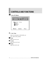
: Color (PC Mode) : Color Temp Adjust color temperature to 9300, 6500, user. (note : 9300 is factory default) : Red Adjust red color for user. : Green Adjust green color for user. : Blue Adjust blue color for user. 13 INSTRUCTION MANUAL
: Color (PC Mode) : Color Temp Adjust color temperature to 9300, 6500, user. (note : 9300 is factory default) : Red Adjust red color for user. : Green Adjust green color for user. : Blue Adjust blue color for user. 13 INSTRUCTION MANUAL
Instruction Manual
Page 15
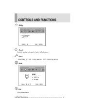
: Utility : Recall Select to reset all setting to the factory default values. : Lock Select ON or OFF (ON : Control key lock. INSTRUCTION MANUAL 14 OFF : Control key unlock) : Exit H :15.7KHz V : 60.0Hz : Exit Turn off OSD Menu.
: Utility : Recall Select to reset all setting to the factory default values. : Lock Select ON or OFF (ON : Control key lock. INSTRUCTION MANUAL 14 OFF : Control key unlock) : Exit H :15.7KHz V : 60.0Hz : Exit Turn off OSD Menu.
Instruction Manual
Page 16
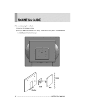
Wall mountable using two methods: 1) Using the 200 mm pre-cut holes 2) Using the VESA standard wall mount design and the 100mm hole pattern on the back panel to install the LCD monitor to the wall. 15 INSTRUCTION MANUAL
Wall mountable using two methods: 1) Using the 200 mm pre-cut holes 2) Using the VESA standard wall mount design and the 100mm hole pattern on the back panel to install the LCD monitor to the wall. 15 INSTRUCTION MANUAL
Instruction Manual
Page 17
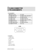
▶ PIN ASSIGNMENTS ▶ ACCESSORY 1. POWER CORD 2. PC cable 4. Remote Control 6. Wall mount (Option) 8. Rack mount (Option). USER'S MANUAL 3. Adaptor 5. Batteries 7. INSTRUCTION MANUAL 16
▶ PIN ASSIGNMENTS ▶ ACCESSORY 1. POWER CORD 2. PC cable 4. Remote Control 6. Wall mount (Option) 8. Rack mount (Option). USER'S MANUAL 3. Adaptor 5. Batteries 7. INSTRUCTION MANUAL 16
Instruction Manual
Page 18
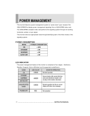
... STANDBY < 5W SUSPEND < 5W ACTIV OFF < 5W LED INDICATOR The power management feature of the monitor is comprised of the VESA DPMS(The display power management signaling) from a VESA DPMS video card. This monitor enters an appropriate mode through not sending horizontal, vertical, or sync signal. This monitor features a power management system to "power down" upon receipt of four stages : On(Green), Standby, Suspend, Active off(Amber) and Unsupported mode(Green). 17 INSTRUCTION MANUAL
... STANDBY < 5W SUSPEND < 5W ACTIV OFF < 5W LED INDICATOR The power management feature of the monitor is comprised of the VESA DPMS(The display power management signaling) from a VESA DPMS video card. This monitor enters an appropriate mode through not sending horizontal, vertical, or sync signal. This monitor features a power management system to "power down" upon receipt of four stages : On(Green), Standby, Suspend, Active off(Amber) and Unsupported mode(Green). 17 INSTRUCTION MANUAL
Instruction Manual
Page 19
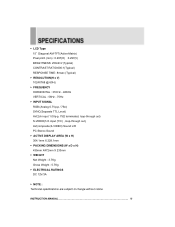
...-TFT(Active-Matrix) Pixel pitch (mm) : 0.297(H) 0.297(V) BRIGHTNESS: 250cd/㎡(Typical) CONTRAST RATIO:600:1(Typical) RESPONSE TIME: 8msec (Typical) ▶ RESOLUTION(H x V) 1024X768 @ 60Hz ▶ FREQUENCY HORIZONTAL : 31KHz - 48KHz VERTICAL : 56Hz - 75Hz ▶ INPUT SIGNAL RGB (Analog 0.7Vp-p / 75Ω) SYNC(Separate TTL Level) AV(2ch input 1.0Vp-p, 75Ω terminated, loop-through out) S-VIDEO(1ch input (Y/C) , loop-through out), AV(composite,S-VIDEO) Sound L/R PC Stereo Sound ▶ ACTIVE DISPLAY...
...-TFT(Active-Matrix) Pixel pitch (mm) : 0.297(H) 0.297(V) BRIGHTNESS: 250cd/㎡(Typical) CONTRAST RATIO:600:1(Typical) RESPONSE TIME: 8msec (Typical) ▶ RESOLUTION(H x V) 1024X768 @ 60Hz ▶ FREQUENCY HORIZONTAL : 31KHz - 48KHz VERTICAL : 56Hz - 75Hz ▶ INPUT SIGNAL RGB (Analog 0.7Vp-p / 75Ω) SYNC(Separate TTL Level) AV(2ch input 1.0Vp-p, 75Ω terminated, loop-through out) S-VIDEO(1ch input (Y/C) , loop-through out), AV(composite,S-VIDEO) Sound L/R PC Stereo Sound ▶ ACTIVE DISPLAY...
Instruction Manual
Page 20
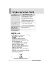
...disposal. 19 INSTRUCTION MANUAL "Going to Sleep" message on screen WEEE Symbols Correct Disposal of This Product (Waste Electrical &Electronic Equipment) (Applicable in the European Union and other European countries with separate collection systems) This marking shown on the product or its working life.To ...prevent possible harm to the environment or human health from other commercial wastes for environmentally safe recycling. Household users should contact either the retailer where they purchased this product,or their supplier and check the terms and ...
...disposal. 19 INSTRUCTION MANUAL "Going to Sleep" message on screen WEEE Symbols Correct Disposal of This Product (Waste Electrical &Electronic Equipment) (Applicable in the European Union and other European countries with separate collection systems) This marking shown on the product or its working life.To ...prevent possible harm to the environment or human health from other commercial wastes for environmentally safe recycling. Household users should contact either the retailer where they purchased this product,or their supplier and check the terms and ...


