Brochure
Page 1
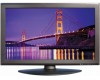
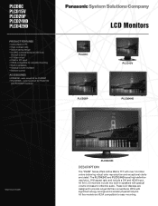
... savings and a smaller physical footprint. rack mount kit for PLCD15V and PLCD20P monitors LCD Monitors PLCD8C PLCD15V PLCD20P PLCD24HD *depends on model PLCD42HD DESCRIPTION The "PLCD" Series offers Active Matrix TFT with loop through outputs • S-Video in/out* • VGA for PC input • VESA compatible for effective audio. All five LCD monitors include two built-in speakers • Gradual volume increase • Remote control ACCESSORIES • PRMK08 - These LCD displays are VESA compatible...
... savings and a smaller physical footprint. rack mount kit for PLCD15V and PLCD20P monitors LCD Monitors PLCD8C PLCD15V PLCD20P PLCD24HD *depends on model PLCD42HD DESCRIPTION The "PLCD" Series offers Active Matrix TFT with loop through outputs • S-Video in/out* • VGA for PC input • VESA compatible for effective audio. All five LCD monitors include two built-in speakers • Gradual volume increase • Remote control ACCESSORIES • PRMK08 - These LCD displays are VESA compatible...
Brochure
Page 2
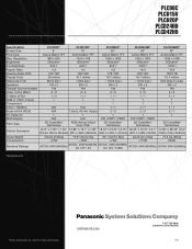
... (gray to gray) Speakers 1W x 2 2W x 2 2W x 2 2W x 2 2W x 2 Gradual Volume Increase Yes Yes Yes Yes Yes Video In/Out (BNC) 2/2 2/2 2/2 2/2 2/2 S-Video In/Out 1/0 1/1 1/1 1/1 1/1 RGB In (15Pin D-Sub) 1 1 1 1 1 Component ~ ~ 1 1 1 DVI In / HDMI In N/A N/A 1/1 1/1 1/1 Audio In/Out (RCA) N/A 1 Set (L+R) / No Output 2/2 2/2 2/1 PC Stereo In 1 1 1 1 1 Multi Display N/A N/A PIP / PBP1 / PBP2 PIP / PBP1 / PBP2 Filter Type 3D Combfilter/ Deinterlace RGB Vertical Stripe Color Filter 3D Combfilter...
... (gray to gray) Speakers 1W x 2 2W x 2 2W x 2 2W x 2 2W x 2 Gradual Volume Increase Yes Yes Yes Yes Yes Video In/Out (BNC) 2/2 2/2 2/2 2/2 2/2 S-Video In/Out 1/0 1/1 1/1 1/1 1/1 RGB In (15Pin D-Sub) 1 1 1 1 1 Component ~ ~ 1 1 1 DVI In / HDMI In N/A N/A 1/1 1/1 1/1 Audio In/Out (RCA) N/A 1 Set (L+R) / No Output 2/2 2/2 2/1 PC Stereo In 1 1 1 1 1 Multi Display N/A N/A PIP / PBP1 / PBP2 PIP / PBP1 / PBP2 Filter Type 3D Combfilter/ Deinterlace RGB Vertical Stripe Color Filter 3D Combfilter...
User Manual
Page 3
SAFETY INSTRUCTION CAUTIONS FCC RF INTERFERENCE STATEMENT CONNECTING WITH EXTERNAL EQUIPMENT REMOTE FUNCTIONS CONTROLS AND FUNCTIONS MOUNTING GUIDE D-SUB CONNECTOR PIN ASSIGNMENTS POWER MANAGEMENT SPECIFICATIONS TROUBLE SHOOTING GUIDE 2 ~ 3 4 5 6 7 8 ~ 31 32 33 34 35 36
SAFETY INSTRUCTION CAUTIONS FCC RF INTERFERENCE STATEMENT CONNECTING WITH EXTERNAL EQUIPMENT REMOTE FUNCTIONS CONTROLS AND FUNCTIONS MOUNTING GUIDE D-SUB CONNECTOR PIN ASSIGNMENTS POWER MANAGEMENT SPECIFICATIONS TROUBLE SHOOTING GUIDE 2 ~ 3 4 5 6 7 8 ~ 31 32 33 34 35 36
User Manual
Page 4
Keep these instructions. 2. Use only with the cart, stand, tripod, bracket or table specified by the manufacturer. 12. Read these Instructions. 3. Heed all instructions. 5. Do not install near water. 6. Do not use this apparatus near any ventilation openings. The wide blade or the third prong are provided for your outlet, consult an electrician for replacement of the polarized or grounding-type plug. Apolarized...
Keep these instructions. 2. Use only with the cart, stand, tripod, bracket or table specified by the manufacturer. 12. Read these Instructions. 3. Heed all instructions. 5. Do not install near water. 6. Do not use this apparatus near any ventilation openings. The wide blade or the third prong are provided for your outlet, consult an electrician for replacement of the polarized or grounding-type plug. Apolarized...
User Manual
Page 6
INSTRUCTION MANUAL 3 CAUTION The power supply cord is used as the main disconnect device, ensure that may be of sufficient magnitude to constitute a risk of electric shock to persons. ATTENTIONN Le cordon d`alimentation est utillsé comme interrupteur général. La prise de courant doit être située ou install...ès This symbol is intended to alert the user to the presence of important operating and maintenance(servicing) instructions in the product's enclosure that the socket-outlet is located/installed near the equipment and is easily accessible. This symbol...
INSTRUCTION MANUAL 3 CAUTION The power supply cord is used as the main disconnect device, ensure that may be of sufficient magnitude to constitute a risk of electric shock to persons. ATTENTIONN Le cordon d`alimentation est utillsé comme interrupteur général. La prise de courant doit être située ou install...ès This symbol is intended to alert the user to the presence of important operating and maintenance(servicing) instructions in the product's enclosure that the socket-outlet is located/installed near the equipment and is easily accessible. This symbol...
User Manual
Page 7
... in a residential installation. NEVER REMOVE THE BACK COVER Removal of the back cover should rest on the power cord. Damage to a power cord can radiate radio frequency energy and, if not installed and used in accordance with the limits for a Class A digital device, pursuant to prevent the temperature from rising. This equipment generates, uses and can cause fire or electrical shock. 4 INSTRUCTION MANUAL NOTE This equipment...
... in a residential installation. NEVER REMOVE THE BACK COVER Removal of the back cover should rest on the power cord. Damage to a power cord can radiate radio frequency energy and, if not installed and used in accordance with the limits for a Class A digital device, pursuant to prevent the temperature from rising. This equipment generates, uses and can cause fire or electrical shock. 4 INSTRUCTION MANUAL NOTE This equipment...
User Manual
Page 8
However, there is no guarantee that to which can be used. Increase the separation between the equipment and receiver. - Only shielded interface cable should be determined by one or more of communications. Consult the dealer or an... INSTRUCTION MANUAL 5 A. Finally, any changes or modifications to the equipment by the user not expressly approved by the grantee or manufacturer could void the users authority to correct the interference by turning the equipment off and on a circuit different from digital apparatus set out in a particular installation. BACK PANEL CONTROL ...
However, there is no guarantee that to which can be used. Increase the separation between the equipment and receiver. - Only shielded interface cable should be determined by one or more of communications. Consult the dealer or an... INSTRUCTION MANUAL 5 A. Finally, any changes or modifications to the equipment by the user not expressly approved by the grantee or manufacturer could void the users authority to correct the interference by turning the equipment off and on a circuit different from digital apparatus set out in a particular installation. BACK PANEL CONTROL ...
User Manual
Page 10
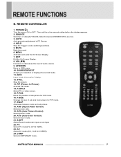
... On Screen Display. 7. S.SET Select Sound mode main input or sub input 22. COMP Select COMPONENT mode. HOLD Stop the Trigger & Auto switching functions. 5. EXIT Exit the On Screen Display. 8. ACC (Auto Color Control) Select Colour mode. 21. POWER( ) Turn the power ON or OFF. AUTO Auto geometry adjustment in PC Source. 4. P.POS Move the position of sub picture for PIP mode. 17. AV Select AV mode.(AV1, AV2 & S-VIDEO). 24. PIP (Picture In Picture) Activate PIP mode. 14. P.SIZE Change the size of audio volume. 9. INSTRUCTION MANUAL...
... On Screen Display. 7. S.SET Select Sound mode main input or sub input 22. COMP Select COMPONENT mode. HOLD Stop the Trigger & Auto switching functions. 5. EXIT Exit the On Screen Display. 8. ACC (Auto Color Control) Select Colour mode. 21. POWER( ) Turn the power ON or OFF. AUTO Auto geometry adjustment in PC Source. 4. P.POS Move the position of sub picture for PIP mode. 17. AV Select AV mode.(AV1, AV2 & S-VIDEO). 24. PIP (Picture In Picture) Activate PIP mode. 14. P.SIZE Change the size of audio volume. 9. INSTRUCTION MANUAL...
User Manual
Page 11
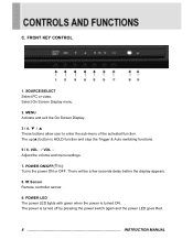
... power LED goes Red. 8 INSTRUCTION MANUAL The power is HOLD function and stop the Trigger & Auto switching functions. 5 / 6. SOURCE/SELECT Select PC or video. VOL / VOL Adjust the volume and menu settings. 7. POWER LED The power LED lights with green when the power is turned ON. Select On Screen Display menu. 2. C. POWER ON/OFF( / I ) Turns the power ON or OFF. MENU Activate and exit the On Screen Display. 3 / 4. ▼ / ▲ These buttons allow user to enter the sub-menu of the activated function. IR Sensor Remote controller...
... power LED goes Red. 8 INSTRUCTION MANUAL The power is HOLD function and stop the Trigger & Auto switching functions. 5 / 6. SOURCE/SELECT Select PC or video. VOL / VOL Adjust the volume and menu settings. 7. POWER LED The power LED lights with green when the power is turned ON. Select On Screen Display menu. 2. C. POWER ON/OFF( / I ) Turns the power ON or OFF. MENU Activate and exit the On Screen Display. 3 / 4. ▼ / ▲ These buttons allow user to enter the sub-menu of the activated function. IR Sensor Remote controller...
User Manual
Page 12
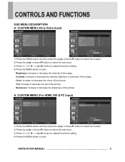
... image. A: CUSTOM MENU (For HDMI, DVI & PC Input) 1) Press the MENU button and then press the up(▲) or down(▼) button to select the Custom. 2) Press the up (▲) or down (▼) button to select the sub menu. 3) Press the left (◀) or right(▶) button to adjust the picture setting. 4) Press the MENU button to save . Contrast: Increase or decrease the intensity (lightness or dimness) of the picture. Brightness...
... image. A: CUSTOM MENU (For HDMI, DVI & PC Input) 1) Press the MENU button and then press the up(▲) or down(▼) button to select the Custom. 2) Press the up (▲) or down (▼) button to select the sub menu. 3) Press the left (◀) or right(▶) button to adjust the picture setting. 4) Press the MENU button to save . Contrast: Increase or decrease the intensity (lightness or dimness) of the picture. Brightness...
User Manual
Page 13
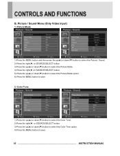
... Video Input) 1. Picture Mode 1) Press the MENU button and then press the up(▲) or down(▼) button to select the Picture / Sound. 2) Press the right(▶) or SOURCE/SELECT button. 3) Press the up(▲) or down(▼) button to select the Picture Mode. 4) Press the right(▶) or SOURCE/SELECT button. 5) Press the up (▲) or down (▼) button to select the Picture Mode option. 6) Press the MENU button to save 2. Color...
... Video Input) 1. Picture Mode 1) Press the MENU button and then press the up(▲) or down(▼) button to select the Picture / Sound. 2) Press the right(▶) or SOURCE/SELECT button. 3) Press the up(▲) or down(▼) button to select the Picture Mode. 4) Press the right(▶) or SOURCE/SELECT button. 5) Press the up (▲) or down (▼) button to select the Picture Mode option. 6) Press the MENU button to save 2. Color...
User Manual
Page 16
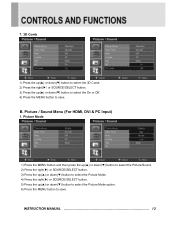
... MENU button to save . Picture / Sound Menu (For HDMI, DVI & PC Input) 1. INSTRUCTION MANUAL 13 Picture Mode 1) Press the MENU button and then press the up(▲) or down(▼) button to select the Picture/Sound. 2) Press the right(▶) or SOURCE/SELECT button. 3) Press the up(▲) or down(▼) button to select the Picture Mode. 4) Press the right(▶) or SOURCE/SELECT button. 5) Press the up (▲) or down (▼) button to select the Picture Mode...
... MENU button to save . Picture / Sound Menu (For HDMI, DVI & PC Input) 1. INSTRUCTION MANUAL 13 Picture Mode 1) Press the MENU button and then press the up(▲) or down(▼) button to select the Picture/Sound. 2) Press the right(▶) or SOURCE/SELECT button. 3) Press the up(▲) or down(▼) button to select the Picture Mode. 4) Press the right(▶) or SOURCE/SELECT button. 5) Press the up (▲) or down (▼) button to select the Picture Mode...
User Manual
Page 19
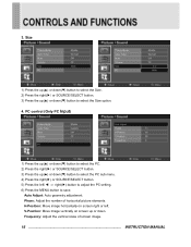
...;) button to save. Frequency: Adjust the vertical noise of horizontal picture elements. V-Position: Move image vertically on screen right or left (◀) or right(▶) button to adjust the PC setting. 6) Press the MENU button to select the Size. 2) Press the right(▶) or SOURCE/SELECT button. 3) Press the up or down. Auto Adjust: Auto geometry adjustment. Phase: Adjust the number of screen image. 16 INSTRUCTION MANUAL H-Position: Move image horizontally on screen up (▲) or down (▼) button to select the Size option. 4. PC control...
...;) button to save. Frequency: Adjust the vertical noise of horizontal picture elements. V-Position: Move image vertically on screen right or left (◀) or right(▶) button to adjust the PC setting. 6) Press the MENU button to select the Size. 2) Press the right(▶) or SOURCE/SELECT button. 3) Press the up or down. Auto Adjust: Auto geometry adjustment. Phase: Adjust the number of screen image. 16 INSTRUCTION MANUAL H-Position: Move image horizontally on screen up (▲) or down (▼) button to select the Size option. 4. PC control...
User Manual
Page 23
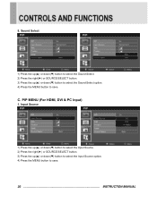
... button. 3) Press the up (▲) or down (▼) button to select the Input Source option. 4) Press the MENU button to save . 20 INSTRUCTION MANUAL Sound Select 1) Press the up(▲) or down(▼) button to select the Sound Select. 2) Press the right(▶) or SOURCE/SELECT button. 3) Press the up (▲) or down (▼) button to select the Sound Select option. 4) Press the MENU button to save . C. 5. PIP MENU (For HDMI, DVI...
... button. 3) Press the up (▲) or down (▼) button to select the Input Source option. 4) Press the MENU button to save . 20 INSTRUCTION MANUAL Sound Select 1) Press the up(▲) or down(▼) button to select the Sound Select. 2) Press the right(▶) or SOURCE/SELECT button. 3) Press the up (▲) or down (▼) button to select the Sound Select option. 4) Press the MENU button to save . C. 5. PIP MENU (For HDMI, DVI...
User Manual
Page 29
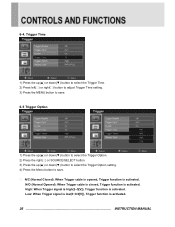
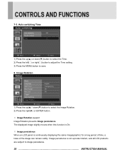
... INSTRUCTION MANUAL Low: When Trigger signal is low(0~0.6[V]), Trigger function is activated. N/O (Normal Opened): When Trigger cable is closed, Trigger function is activated. 6-4. High: When Trigger signal is high(2~5[V]), Trigger function is activated. Trigger Time 1) Press the up(▲) or down(▼) button to select the Trigger Time. 2) Press left( ) or right( ) button to adjust Trigger Time setting. 3) Press the MENU button...
... INSTRUCTION MANUAL Low: When Trigger signal is low(0~0.6[V]), Trigger function is activated. N/O (Normal Opened): When Trigger cable is closed, Trigger function is activated. 6-4. High: When Trigger signal is high(2~5[V]), Trigger function is activated. Trigger Time 1) Press the up(▲) or down(▼) button to select the Trigger Time. 2) Press left( ) or right( ) button to adjust Trigger Time setting. 3) Press the MENU button...
User Manual
Page 30
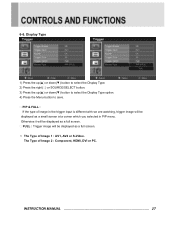
... SOURCE/SELECT button. 3) Press the up(▲) or down(▼) button to select the Display Type option. 4) Press the Menu button to save. The Type of Image 1 : AV1, AV2 or S-Video. 6-6. INSTRUCTION MANUAL 27 PIP & FULL : If the type of image in the trigger input is different with we are watching, trigger image will be displayed as a full screen. Otherwise it will be displayed as a small screen at...
... SOURCE/SELECT button. 3) Press the up(▲) or down(▼) button to select the Display Type option. 4) Press the Menu button to save. The Type of Image 1 : AV1, AV2 or S-Video. 6-6. INSTRUCTION MANUAL 27 PIP & FULL : If the type of image in the trigger input is different with we are watching, trigger image will be displayed as a full screen. Otherwise it will be displayed as a small screen at...
User Manual
Page 33
... setting. 3) Press the MENU button to image persistence. 30 INSTRUCTION MANUAL Image Rotation 1) Press the up (▲) or down (▼) button to select the Image Rotation. 2) Press the right(▶) or ENTER button. ※ Image Rotation support Image Rotation prevents Image persistence. The displayed image slightly moves when this function is On. ※ Image persistence When an LCD panel is not a product defect, and all LCD products are subject to save...
... setting. 3) Press the MENU button to image persistence. 30 INSTRUCTION MANUAL Image Rotation 1) Press the up (▲) or down (▼) button to select the Image Rotation. 2) Press the right(▶) or ENTER button. ※ Image Rotation support Image Rotation prevents Image persistence. The displayed image slightly moves when this function is On. ※ Image persistence When an LCD panel is not a product defect, and all LCD products are subject to save...
User Manual
Page 34
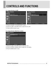
8-1. Image Rotation Min(Time control) 1) Press the up (▲) or down (▼) button to select the Time. 2) Press the left(◀) or right(▶) button to adjust the Time setting. 3) Press the MENU button to save . INSTRUCTION MANUAL 31 Image Rotation On/Off 1) Press the right(▶) or SOURCE/SELECT button. 2) Press the up (▲) or down (▼) button to select the On or Off . 3) Press the Menu button to save . 8-2.
8-1. Image Rotation Min(Time control) 1) Press the up (▲) or down (▼) button to select the Time. 2) Press the left(◀) or right(▶) button to adjust the Time setting. 3) Press the MENU button to save . INSTRUCTION MANUAL 31 Image Rotation On/Off 1) Press the right(▶) or SOURCE/SELECT button. 2) Press the up (▲) or down (▼) button to select the On or Off . 3) Press the Menu button to save . 8-2.
User Manual
Page 37
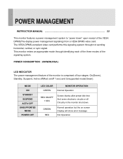
... of the monitor is comprised of the VESA DPMS(The display power management signaling) from a VESA DPMS video card. GREEN RED Normal operation but the on /off 1 sec) and Unsupported mode(Green). INSTRUCTION MANUAL 33 This monitor features a power management system to "power down . The VESA DPMS-compliant video card performs this signaling system through identifying each of the three modes of the signaling system. This monitor enters an appropriate mode through not sending horizontal, vertical, or sync signal.
... of the monitor is comprised of the VESA DPMS(The display power management signaling) from a VESA DPMS video card. GREEN RED Normal operation but the on /off 1 sec) and Unsupported mode(Green). INSTRUCTION MANUAL 33 This monitor features a power management system to "power down . The VESA DPMS-compliant video card performs this signaling system through identifying each of the three modes of the signaling system. This monitor enters an appropriate mode through not sending horizontal, vertical, or sync signal.
User Manual
Page 38
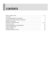
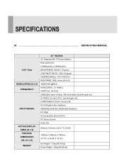
34 INSTRUCTION MANUAL LCD- Type RESOLUTION (H x V) FREQUENCY INPUT SIGNAL ACTIVE DISPLAY AREA (H x V) PACKING DIMENSIONS (W x H x D) WEIGHT 42'' WUXGA 42˝ Diagonal AM-TFT(Active-Matrix) Pixel pitch(mm) : 0.4845mm(H) x 0.4845mm(V) BRIGHTNESS: 500cd/㎡(Typical) CONTRAST RATIO: 1300:1(Typical) VIEWING ANGLE: 178°/178°(H/V) RESPONSE TIME: 5msec(G-to-G) 1920X1080 @60Hz HORIZONTAL: 31- 80KHz VERTICAL: 56-75Hz VIDEO(2ch input 1.0Vp-p, 75Ω terminated, loop-through out) S-VIDEO(1ch input (Y/C), loop-through...
34 INSTRUCTION MANUAL LCD- Type RESOLUTION (H x V) FREQUENCY INPUT SIGNAL ACTIVE DISPLAY AREA (H x V) PACKING DIMENSIONS (W x H x D) WEIGHT 42'' WUXGA 42˝ Diagonal AM-TFT(Active-Matrix) Pixel pitch(mm) : 0.4845mm(H) x 0.4845mm(V) BRIGHTNESS: 500cd/㎡(Typical) CONTRAST RATIO: 1300:1(Typical) VIEWING ANGLE: 178°/178°(H/V) RESPONSE TIME: 5msec(G-to-G) 1920X1080 @60Hz HORIZONTAL: 31- 80KHz VERTICAL: 56-75Hz VIDEO(2ch input 1.0Vp-p, 75Ω terminated, loop-through out) S-VIDEO(1ch input (Y/C), loop-through...


