Functional Instructions
Page 2
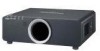
... - 2 LAMP POWER 29 STANDBY MODE 29 RS-232C 29 REMOTE2 MODE 29 STATUS 30 FILTER COUNTER RESET 30 NO SIGNAL SHUT-OFF 30 FUNCTION BUTTON 30 DATE AND TIME 31 SAVE ALL USERS DATA 31 LOAD ALL USERS DATA 31 INITIALIZE 31 SERVICE PASSWORD 31 TEST PATTERN 32 TEST PATTERN 32 SIGNAL LIST 33 SECURITY menu 35 SECURITY PASSWORD 35 SECURITY PASSWORD CHANGE 35 DISPLAY SETTING 35 TEXT CHANGE 35 MENU LOCK 36 MENU LOCK PASSWORD 36 CONTROL DEVICE SETUP 36 NETWORK menu 37 NETWORK SETUP 37 NETWORK CONTROL 37 NETWORK STATUS...
... - 2 LAMP POWER 29 STANDBY MODE 29 RS-232C 29 REMOTE2 MODE 29 STATUS 30 FILTER COUNTER RESET 30 NO SIGNAL SHUT-OFF 30 FUNCTION BUTTON 30 DATE AND TIME 31 SAVE ALL USERS DATA 31 LOAD ALL USERS DATA 31 INITIALIZE 31 SERVICE PASSWORD 31 TEST PATTERN 32 TEST PATTERN 32 SIGNAL LIST 33 SECURITY menu 35 SECURITY PASSWORD 35 SECURITY PASSWORD CHANGE 35 DISPLAY SETTING 35 TEXT CHANGE 35 MENU LOCK 36 MENU LOCK PASSWORD 36 CONTROL DEVICE SETUP 36 NETWORK menu 37 NETWORK SETUP 37 NETWORK CONTROL 37 NETWORK STATUS...

Functional Instructions
Page 17
... pressing I, H or the ENTER button, and press I H Setting range: 0 to +10 More natural white Whiter NOISE REDUCTION You can select manually. Press I H to adjust the value. OFF 1 2 3 Deactive Low Middle High SHARPNESS You can adjust the brightness of white area of the image. VIDEO/S-VIDEO terminal AUTO HNTSC HNTSC 4.43 HPAL HPAL-M HPAL-N HSECAM HPAL60 • AUTO is changed, the projector detects the colour system...
... pressing I, H or the ENTER button, and press I H Setting range: 0 to +10 More natural white Whiter NOISE REDUCTION You can select manually. Press I H to adjust the value. OFF 1 2 3 Deactive Low Middle High SHARPNESS You can adjust the brightness of white area of the image. VIDEO/S-VIDEO terminal AUTO HNTSC HNTSC 4.43 HPAL HPAL-M HPAL-N HSECAM HPAL60 • AUTO is changed, the projector detects the colour system...

Functional Instructions
Page 22
... signals from RGB 1 IN/RGB 2 IN only. DIGITAL CINEMA REALITY You can adjust to 2:3 pulldown. H: Moves the inner edge of the image to change the setting properly. UPPER LOWER Q Setting range Models PT-DZ6710E/PT-DZ6700E PT-DW6300E PT-D6000E Vertical 0 - 599 0 - 399 0 - 383 Horizontal 0 - 959 0 - 639 0 - 511 INPUT RESOLUTION Input resolution adjustment achieves the best image when the screen flickers or halo is not 2:2 pulldown may be distorted during image projection using...
... signals from RGB 1 IN/RGB 2 IN only. DIGITAL CINEMA REALITY You can adjust to 2:3 pulldown. H: Moves the inner edge of the image to change the setting properly. UPPER LOWER Q Setting range Models PT-DZ6710E/PT-DZ6700E PT-DW6300E PT-D6000E Vertical 0 - 599 0 - 399 0 - 383 Horizontal 0 - 959 0 - 639 0 - 511 INPUT RESOLUTION Input resolution adjustment achieves the best image when the screen flickers or halo is not 2:2 pulldown may be distorted during image projection using...
Functional Instructions
Page 26
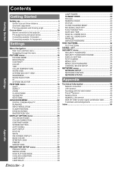
... x 1 050 For specific resolution signals Select the required MODE and change the displaying position of the warning messages will be encountered with YPBPR or RGB of waning messages. Refer the instructions of the warning messages will be displayed. ON OFF All of the connected equipment. • DVI signal is too close to select the required option. 1 Yellow 2 Blue 3 White 4 Green 5 Pink 6 Brown J OSD MEMORY The current menu cursor position will...
... x 1 050 For specific resolution signals Select the required MODE and change the displaying position of the warning messages will be encountered with YPBPR or RGB of waning messages. Refer the instructions of the warning messages will be displayed. ON OFF All of the connected equipment. • DVI signal is too close to select the required option. 1 Yellow 2 Blue 3 White 4 Green 5 Pink 6 Brown J OSD MEMORY The current menu cursor position will...

Functional Instructions
Page 29
... to light White: Any other lamp for using the projector for a continuous period of the projection lamp can be turned off for 2 hours, then for only the other status. • If the projector is necessary. NOTE: • With ECO setting, NETWORK function, RS-232C output and some of use lamp will light first. Selects the Lamp unit 1. STANDBY MODE You can customise the REMOTE 2 IN terminal function. USER For changing an optional input...
... to light White: Any other lamp for using the projector for a continuous period of the projection lamp can be turned off for 2 hours, then for only the other status. • If the projector is necessary. NOTE: • With ECO setting, NETWORK function, RS-232C output and some of use lamp will light first. Selects the Lamp unit 1. STANDBY MODE You can customise the REMOTE 2 IN terminal function. USER For changing an optional input...

Functional Instructions
Page 30
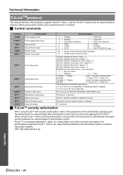
... PROJECTOR SETUP menu STATUS You can see the status of times LAMP1 LAMP2 ON Displays the has been lit. REMAINING FILTER Displays the filter runtime. MAIN VERSION Displays the main version of the firmware of the input signal. FG 70 MIN. Options Functions DISABLE Deactivate the FUNCTION button. SIGNAL FREQUENCY Displays the frequency of the projector unit. INTAKE AIR TEMP. number of times LAMP2 SHUTTER Displays the number of LAMP1. FILTER COUNTER RESET After you replaced the Auto Cleaning Filter (ACF...
... PROJECTOR SETUP menu STATUS You can see the status of times LAMP1 LAMP2 ON Displays the has been lit. REMAINING FILTER Displays the filter runtime. MAIN VERSION Displays the main version of the firmware of the input signal. FG 70 MIN. Options Functions DISABLE Deactivate the FUNCTION button. SIGNAL FREQUENCY Displays the frequency of the projector unit. INTAKE AIR TEMP. number of times LAMP2 SHUTTER Displays the number of LAMP1. FILTER COUNTER RESET After you replaced the Auto Cleaning Filter (ACF...

Functional Instructions
Page 34
... the screen after adjustment. Displays the REGISTERED SIGNAL STATUS and change . Displays the SUB MEMORY LIST. 2. Press I or H while the menu is registered in the unused memory with change the name if necessary. You can return to the previous step by pressing the MENU button. 3. Location address Sub memory number: NOTE: • The memories are used, the data of the old signals is cleared from the screen after adjustment. Settings...
... the screen after adjustment. Displays the REGISTERED SIGNAL STATUS and change . Displays the SUB MEMORY LIST. 2. Press I or H while the menu is registered in the unused memory with change the name if necessary. You can return to the previous step by pressing the MENU button. 3. Location address Sub memory number: NOTE: • The memories are used, the data of the old signals is cleared from the screen after adjustment. Settings...
Functional Instructions
Page 44
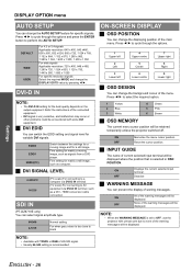
... trademark in NETWORK menu. For specifications regarding PJLink™, refer to perform projector setting and projector status query operations from 0 - 2 are as follows. 0 = No error known 1 = Warning 2 = Error 1st digits (1 - 5 digits): Lamp 1 cumulative operating time 2nd digit: 0 = Lamp 1 off, 1 = Lamp 1 on 3rd digits (1 - 5 digits): Lamp 2 cumulative operating time 4th digit: 0 = Lamp 2 off (picture mute cancelled) 31 = Shutter mode on The following are returned as parameters. Control details Power supply control Power supply status query Input selection Input selection...
... trademark in NETWORK menu. For specifications regarding PJLink™, refer to perform projector setting and projector status query operations from 0 - 2 are as follows. 0 = No error known 1 = Warning 2 = Error 1st digits (1 - 5 digits): Lamp 1 cumulative operating time 2nd digit: 0 = Lamp 1 off, 1 = Lamp 1 on 3rd digits (1 - 5 digits): Lamp 2 cumulative operating time 4th digit: 0 = Lamp 2 off (picture mute cancelled) 31 = Shutter mode on The following are returned as parameters. Control details Power supply control Power supply status query Input selection Input selection...

Functional Instructions
Page 50
... 23 F FILTER COUNTER RESET 30 FREEZE 27 Front leg adjusters 9 FUNCTION BUTTON 30 G GEOMETRY 19 CURVED 20 Geometric adjustment 8 KEYSTONE 20 H HIGH ALTITUDE MODE 28 I INITIALIZE 31 INPUT GUIDE 26 INPUT RESOLUTION 22 INSTALLATION 28 K KEYSTONE 21 L LAMP POWER 29 LAMP RELAY 29 LAMP SELECT 29 LOAD ALL USERS DATA 31 M Menu Navigation 15 Structure 12 MENU LOCK 36 MENU LOCK PASSWORD 36 N NETWORK 37 Network Connection 38 Detailed set up 41 LAN terminal 38 Projector Control 40 NETWORK CONTROL 37 NETWORK SETUP 37 NETWORK STATUS 37 NO SIGNAL SHUT-OFF 30...
... 23 F FILTER COUNTER RESET 30 FREEZE 27 Front leg adjusters 9 FUNCTION BUTTON 30 G GEOMETRY 19 CURVED 20 Geometric adjustment 8 KEYSTONE 20 H HIGH ALTITUDE MODE 28 I INITIALIZE 31 INPUT GUIDE 26 INPUT RESOLUTION 22 INSTALLATION 28 K KEYSTONE 21 L LAMP POWER 29 LAMP RELAY 29 LAMP SELECT 29 LOAD ALL USERS DATA 31 M Menu Navigation 15 Structure 12 MENU LOCK 36 MENU LOCK PASSWORD 36 N NETWORK 37 Network Connection 38 Detailed set up 41 LAN terminal 38 Projector Control 40 NETWORK CONTROL 37 NETWORK SETUP 37 NETWORK STATUS 37 NO SIGNAL SHUT-OFF 30...

Operating Instructions
Page 5
... steps Getting Started 1. Adjust the image See "Menu Navigation" on page 14. Setting up " on page 19. Projecting 19 Projecting a image 19 Remote control operation 21 Operating range 21 Setting up the image position automatically 21 Switching the input signal 22 Stopping the projection 22 Clearing the screen 22 Changing the picture aspect ratio 22 Displaying the internal test pattern 22 Using an assigned function 23 Displaying the status of the projector 23 Resetting to safety 6 WARNINGS 6 CAUTIONS...
... steps Getting Started 1. Adjust the image See "Menu Navigation" on page 14. Setting up " on page 19. Projecting 19 Projecting a image 19 Remote control operation 21 Operating range 21 Setting up the image position automatically 21 Switching the input signal 22 Stopping the projection 22 Clearing the screen 22 Changing the picture aspect ratio 22 Displaying the internal test pattern 22 Using an assigned function 23 Displaying the status of the projector 23 Resetting to safety 6 WARNINGS 6 CAUTIONS...

Operating Instructions
Page 9
... projector. Cautions when installing Avoid setting up the projector near high-voltage power lines or near the screen to carry out all installation work . See "TEMP indicator" on the environment. If using the projector, close the front panel cover. Moreover, when not using this may cause malfunctions or accidents. Failure to vibration or shocks. Be sure to your bare hands. Please take non repairable units back to install the projection lens cover...
... projector. Cautions when installing Avoid setting up the projector near high-voltage power lines or near the screen to carry out all installation work . See "TEMP indicator" on the environment. If using the projector, close the front panel cover. Moreover, when not using this may cause malfunctions or accidents. Failure to vibration or shocks. Be sure to your bare hands. Please take non repairable units back to install the projection lens cover...

Operating Instructions
Page 12
... (page 29) STANDBY(RED)/ ON(GREEN) LAMP TEMP FILTER Lamp unit compartment (page 30) Air exhaust port STANDBY(RED)/ ON(GREEN) LAMP TEMP FILTER Projection lens Focus ring Remote control signal receptor (page 21) Front leg adjusters Screw up/down to the standby mode. (page 20) Burglar hook port Attach a commercial burglar prevention cable. ENGLISH - 12 While the auto setup feature is not in the standby mode. (page 20) POWER STANDBY button Returns to adjust the projection angle. POWER ON button Starts the projection while in use, keep the projector lens cover attached to...
... (page 29) STANDBY(RED)/ ON(GREEN) LAMP TEMP FILTER Lamp unit compartment (page 30) Air exhaust port STANDBY(RED)/ ON(GREEN) LAMP TEMP FILTER Projection lens Focus ring Remote control signal receptor (page 21) Front leg adjusters Screw up/down to the standby mode. (page 20) Burglar hook port Attach a commercial burglar prevention cable. ENGLISH - 12 While the auto setup feature is not in the standby mode. (page 20) POWER STANDBY button Returns to adjust the projection angle. POWER ON button Starts the projection while in use, keep the projector lens cover attached to...

Operating Instructions
Page 13
... port Air intake port POWER button Switch the projector on the POWER button of the projector body that is located near the terminals before using the control buttons. • Do not cover the ventilation openings or place anything within 50 cm (20") of them as this may cause damage or injury. Auto Cleaning Filter (ACF) compartment (page 31) NOTE: • Switch on /off. (page 20) AC IN terminal Connect the power cord to supply...
... port Air intake port POWER button Switch the projector on the POWER button of the projector body that is located near the terminals before using the control buttons. • Do not cover the ventilation openings or place anything within 50 cm (20") of them as this may cause damage or injury. Auto Cleaning Filter (ACF) compartment (page 31) NOTE: • Switch on /off. (page 20) AC IN terminal Connect the power cord to supply...
Operating Instructions
Page 19
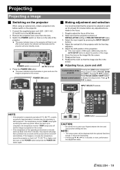
... indicator will illuminate and the projector will enter standby mode. If the input signal is projected on that the image size fits in green and soon the image is RGB signal, additionally press the AUTO SETUP button to the AC IN terminal. 2. Zoom the lens so the image fills the screen. 7. Connect the supplied power cord (220 - 240 V AC, 50 Hz/60 Hz) to adjust the position of FOCUS, ZOOM and SHIFT. Select and set the projection scheme...
... indicator will illuminate and the projector will enter standby mode. If the input signal is projected on that the image size fits in green and soon the image is RGB signal, additionally press the AUTO SETUP button to the AC IN terminal. 2. Zoom the lens so the image fills the screen. 7. Connect the supplied power cord (220 - 240 V AC, 50 Hz/60 Hz) to adjust the position of FOCUS, ZOOM and SHIFT. Select and set the projection scheme...

Operating Instructions
Page 20
... POWER STANDBY button. The cooling fan keeps running , never turn on the projector or SHIFT button of the remote control for 5 seconds. 2. Using the standard projection position as this may cause a change in the focus. J Direct power off function The power supplied internally causes the cooling fan to continue operating and cool off . Q PT-DW6300U Standard projection position Basic Operation ENGLISH - 20 Projecting J Switching off function, it sometimes takes longer than usual for the lamp...
... POWER STANDBY button. The cooling fan keeps running , never turn on the projector or SHIFT button of the remote control for 5 seconds. 2. Using the standard projection position as this may cause a change in the focus. J Direct power off function The power supplied internally causes the cooling fan to continue operating and cool off . Q PT-DW6300U Standard projection position Basic Operation ENGLISH - 20 Projecting J Switching off function, it sometimes takes longer than usual for the lamp...

Operating Instructions
Page 28
... LAMP" message on the screen unit used hours have reached 1 800 hours. Turn on • Wait until the lamp has cooled off, and then immediately after turning it off the POWER switch of the projector in proper way and contact the dealer. • Turn off the projector in red 3 times Information Check point Remedial measure • Did you notice a "REPLACE • This lamp monitor lights up status High temperature inside. (WARNING) High temperature inside. (Standby condition) Cooling fan...
... LAMP" message on the screen unit used hours have reached 1 800 hours. Turn on • Wait until the lamp has cooled off, and then immediately after turning it off the POWER switch of the projector in proper way and contact the dealer. • Turn off the projector in red 3 times Information Check point Remedial measure • Did you notice a "REPLACE • This lamp monitor lights up status High temperature inside. (WARNING) High temperature inside. (Standby condition) Cooling fan...

Operating Instructions
Page 29
... ACF unit is operating, operational sound may cause malfunction of STATUS in PROJECTOR SETUP menu is not installed, displays "THE AIR FILTER HAS NOT BEEN INSTALLED PROPERLY." Monitor Lamp indicators J FILTER indicator The FILTER indicates the Auto Cleaning Filter (ACF) unit status. Lamp indication Information Check point Remedial measure Lighting in PROJECTOR SETUP menu. When the ACF unit is OFF, it may be heard. • In a dusty environment, the guided remaining use time of STATUS in red • Check the REMAINING FILTER • Replace the ACF unit...
... ACF unit is operating, operational sound may cause malfunction of STATUS in PROJECTOR SETUP menu is not installed, displays "THE AIR FILTER HAS NOT BEEN INSTALLED PROPERLY." Monitor Lamp indicators J FILTER indicator The FILTER indicates the Auto Cleaning Filter (ACF) unit status. Lamp indication Information Check point Remedial measure Lighting in PROJECTOR SETUP menu. When the ACF unit is OFF, it may be heard. • In a dusty environment, the guided remaining use time of STATUS in red • Check the REMAINING FILTER • Replace the ACF unit...

Operating Instructions
Page 30
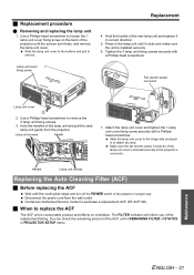
... PROJECTOR SETUP menu. Automatically the projector will stay until you respond. Maintenance ENGLISH - 30 NOTE: • The guide times, 1 800 and 2 000 hours, are rough estimates based on the ceiling, do not work directly under the projector or put your face closer to replace the lamp unit The lamp unit is provided with an unauthorized lamp unit. Replacement Replacing the Lamp unit J Before replacing the Lamp unit Turn off . On screen LAMP indicator Indication REPLACE LAMP...
... PROJECTOR SETUP menu. Automatically the projector will stay until you respond. Maintenance ENGLISH - 30 NOTE: • The guide times, 1 800 and 2 000 hours, are rough estimates based on the ceiling, do not work directly under the projector or put your face closer to replace the lamp unit The lamp unit is provided with an unauthorized lamp unit. Replacement Replacing the Lamp unit J Before replacing the Lamp unit Turn off . On screen LAMP indicator Indication REPLACE LAMP...
Operating Instructions
Page 31
... REMAINING FILTER of the lamp unit and pull the used lamp unit gently from the wall outlet. Handle Lamp unit screws Replacing the Auto Cleaning Filter (ACF) J Before replacing the ACF Wait until it in PROJECTOR SETUP menu. The FILTER indicator will inform you of the lamp unit cover is inserted securely to attach securely. Press in the lamp unit until the cooling fan stops and turn freely, and remove the lamp unit cover. Use...
... REMAINING FILTER of the lamp unit and pull the used lamp unit gently from the wall outlet. Handle Lamp unit screws Replacing the Auto Cleaning Filter (ACF) J Before replacing the ACF Wait until it in PROJECTOR SETUP menu. The FILTER indicator will inform you of the lamp unit cover is inserted securely to attach securely. Press in the lamp unit until the cooling fan stops and turn freely, and remove the lamp unit cover. Use...

Operating Instructions
Page 33
... VCR or other signal source. Problem Cause Power does not turn on. No picture appears. The POWER switch is being input. The video signal input source may be out of the projector do not operate. The BRIGHTNESS adjustment setting may not have a problem. The input source which is not compatible with your dealer. The lens focus may be updated to the latest version. The projector may not be at the correct distance from a laptop computer may...
... VCR or other signal source. Problem Cause Power does not turn on. No picture appears. The POWER switch is being input. The video signal input source may be out of the projector do not operate. The BRIGHTNESS adjustment setting may not have a problem. The input source which is not compatible with your dealer. The lens focus may be updated to the latest version. The projector may not be at the correct distance from a laptop computer may...

