
PT50PD3P User Guide
Page 5
... Instructions 3 ASPECT Controls 22 FCC STATEMENT 6 Adjusting PICTURE POS./SIZE 24 Safety Precautions 7 SOUND Adjustment 26 Accessories 9 MUTE 26 Accessories Supplied 9 SURROUND Controls 27 Optional Accessories 9 PICTURE Adjustments 28 Remote Control Batteries 10 SET UP for Input Signals 30 Basic Controls 11 COMPONENT/RGB IN SELECT 30 Connections 12 Adjusting unnatural video images How to connect the speakers 13 (3D Y/C FILTER 30 How to connect the AV Input Terminals 13 COLOR SYSTEM / Panasonic AUTO 31 How to connect the TUNER Input...
... Instructions 3 ASPECT Controls 22 FCC STATEMENT 6 Adjusting PICTURE POS./SIZE 24 Safety Precautions 7 SOUND Adjustment 26 Accessories 9 MUTE 26 Accessories Supplied 9 SURROUND Controls 27 Optional Accessories 9 PICTURE Adjustments 28 Remote Control Batteries 10 SET UP for Input Signals 30 Basic Controls 11 COMPONENT/RGB IN SELECT 30 Connections 12 Adjusting unnatural video images How to connect the speakers 13 (3D Y/C FILTER 30 How to connect the AV Input Terminals 13 COLOR SYSTEM / Panasonic AUTO 31 How to connect the TUNER Input...

PT50PD3P User Guide
Page 6
...; Reorient or relocate the receiving antenna. • Increase the separation between the equipment and receiver. • Connect the equipment into an outlet on pages 13, and 16. Operation is no guarantee that to which can radiate radio frequency energy and, if not installed and used when connecting this high definition plasma display to video equipment; Refer to instructions on a circuit different...
...; Reorient or relocate the receiving antenna. • Increase the separation between the equipment and receiver. • Connect the equipment into an outlet on pages 13, and 16. Operation is no guarantee that to which can radiate radio frequency energy and, if not installed and used when connecting this high definition plasma display to video equipment; Refer to instructions on a circuit different...

PT50PD3P User Guide
Page 8
... of still pictures include logos, video games, computer images, teletext and images displayed in contact with articles made from rubber or PVC. Safety Precautions CAUTION This High Definition Plasma Display is for use only with the following accessories are manufactured by Matsushita Electric Industrial Co., Ltd.) • Speakers TY-SP50PHD3W • Pedestal TY-ST42PT1U • Wall stand TY-ST42PW1 • Wall-hanging bracket (angled TY...
... of still pictures include logos, video games, computer images, teletext and images displayed in contact with articles made from rubber or PVC. Safety Precautions CAUTION This High Definition Plasma Display is for use only with the following accessories are manufactured by Matsushita Electric Industrial Co., Ltd.) • Speakers TY-SP50PHD3W • Pedestal TY-ST42PT1U • Wall stand TY-ST42PW1 • Wall-hanging bracket (angled TY...

PT50PD3P User Guide
Page 9
... and items shown Operating Instruction book Remote Control Transmitter EUR646525 INPUT SURROUND VOL N R Batteries for the Remote Control Transmitter (AA(R6) Battery × 2) PICTURE SOUND SET UP PICTURE POS. /SIZE ASPECT PC OFF TIMER PLASMA DISPLAY Warranty RCA/BNC Adapter Plug Ferrite core KRCBC160928B Speaker Wire × 2 Optional Accessories • Speakers TY-SP50PHD3W • Pedestal TY-ST42PT1U • Wall stand TY-ST42PW1 • Wall-hanging bracket (angled) TY-WK42PR1 • Connecting Cable TY-SCP15C03 49...
... and items shown Operating Instruction book Remote Control Transmitter EUR646525 INPUT SURROUND VOL N R Batteries for the Remote Control Transmitter (AA(R6) Battery × 2) PICTURE SOUND SET UP PICTURE POS. /SIZE ASPECT PC OFF TIMER PLASMA DISPLAY Warranty RCA/BNC Adapter Plug Ferrite core KRCBC160928B Speaker Wire × 2 Optional Accessories • Speakers TY-SP50PHD3W • Pedestal TY-ST42PT1U • Wall stand TY-ST42PW1 • Wall-hanging bracket (angled) TY-WK42PR1 • Connecting Cable TY-SCP15C03 49...
PT50PD3P User Guide
Page 11
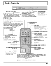
... off timer cancelled) each time the button is used to switch OFF TIMER button directly to display the current system status. The setting changes to stand-by after a fixed period. R button (see page 22) 3 Off timer VOL N R Press the Volume Up "+" or Down "-" button to turn the High Definition Plasma Display ON, from STANDBY mode. Indicator not illuminated (The unit will light. • Power-OFF ..... Green Input button (VIDEO (S-VIDEO)/COMPONENT, RGB/PC Mode Selection) Push the "INPUT" button to STANDBY mode. Push...
... off timer cancelled) each time the button is used to switch OFF TIMER button directly to display the current system status. The setting changes to stand-by after a fixed period. R button (see page 22) 3 Off timer VOL N R Press the Volume Up "+" or Down "-" button to turn the High Definition Plasma Display ON, from STANDBY mode. Indicator not illuminated (The unit will light. • Power-OFF ..... Green Input button (VIDEO (S-VIDEO)/COMPONENT, RGB/PC Mode Selection) Push the "INPUT" button to STANDBY mode. Push...
PT50PD3P User Guide
Page 13
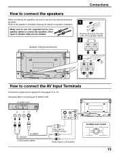
... Input Terminals Connect the signal source equipment (see pages 14 to 17). (Example) When connecting an S-VIDEO VCR (S-VIDEO VCR) Audio R OUT L Video OUT S-Video OUT AUDIO S-VIDEO 2×RCA audio cables L S-VIDEO VIDEO AV IN AUDIO R Video input to S-VIDEO socket Audio input to L/R sockets S-VIDEO 4 pin socket Luminance earth Chrominance earth Luminance in Chrominance in 13 Refer to the speaker's Installation Manual for details on speaker installation. Connections How to connect the speakers When connecting the speakers, be sure to use the supplied...
... Input Terminals Connect the signal source equipment (see pages 14 to 17). (Example) When connecting an S-VIDEO VCR (S-VIDEO VCR) Audio R OUT L Video OUT S-Video OUT AUDIO S-VIDEO 2×RCA audio cables L S-VIDEO VIDEO AV IN AUDIO R Video input to S-VIDEO socket Audio input to L/R sockets S-VIDEO 4 pin socket Luminance earth Chrominance earth Luminance in Chrominance in 13 Refer to the speaker's Installation Manual for details on speaker installation. Connections How to connect the speakers When connecting the speakers, be sure to use the supplied...
PT50PD3P User Guide
Page 14
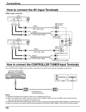
...Video OUT VIDEO BNC video cable AUDIO 2×RCA audio cables VIDEO RCA video cable AUDIO 2×RCA audio cables Video input to BNC socket Audio input to L/R sockets L S-VIDEO VIDEO AV IN Video input to BNC socket AUDIO R RCA-BNC adapter plug Audio input to L/R sockets How to the High Definition Plasma Display and CONTROLLER/TUNER is reserved for use with this set. (2) When connecting video cables, priority is given to the S-VIDEO cable when the S-VIDEO input terminal and the video input terminal are not supplied with future external compatible components. CONTROLLER/TUNER (Model...
...Video OUT VIDEO BNC video cable AUDIO 2×RCA audio cables VIDEO RCA video cable AUDIO 2×RCA audio cables Video input to BNC socket Audio input to L/R sockets L S-VIDEO VIDEO AV IN Video input to BNC socket AUDIO R RCA-BNC adapter plug Audio input to L/R sockets How to the High Definition Plasma Display and CONTROLLER/TUNER is reserved for use with this set. (2) When connecting video cables, priority is given to the S-VIDEO cable when the S-VIDEO input terminal and the video input terminal are not supplied with future external compatible components. CONTROLLER/TUNER (Model...
PT50PD3P User Guide
Page 15
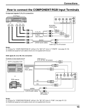
... equipment and cables shown are not supplied with this set . Connections How to connect the COMPONENT/RGB Input Terminals Component signals (Y, PB, PR) connection DVD Player L Audio R OUT L DVD (Y,PB, PR) OUT Y PB PR VD RCA-BNC adapter plug HD PR/CR/R PB/CB/B Y/G COMPONENT/RGB IN AUDIO R Y, PB, PR 3×RCA video cables AUDIO 2×RCA audio cables Audio input to L/R sockets Notes: (1) Change the "COMPONENT/RGB-IN" setting in the "SET UP" menu to...
... equipment and cables shown are not supplied with this set . Connections How to connect the COMPONENT/RGB Input Terminals Component signals (Y, PB, PR) connection DVD Player L Audio R OUT L DVD (Y,PB, PR) OUT Y PB PR VD RCA-BNC adapter plug HD PR/CR/R PB/CB/B Y/G COMPONENT/RGB IN AUDIO R Y, PB, PR 3×RCA video cables AUDIO 2×RCA audio cables Audio input to L/R sockets Notes: (1) Change the "COMPONENT/RGB-IN" setting in the "SET UP" menu to...
PT50PD3P User Guide
Page 16
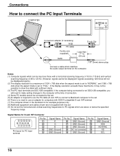
... cable D-sub 15p Ferrite core (supplied) Audio Less than 7" 7/8 (20 cm) 1/8" (3mm) stereo plug Connect a cable which are DDC1/2B-compatible. Notes: (1) Computer signals which can be input are not supplied with a horizontal scanning frequency of 15.5 to 110 kHz and vertical scanning frequency of 48 to 120 Hz. (However, signals cannot be displayed if signals exceeding 1200 lines will need to make setting changes to the computer at the time...
... cable D-sub 15p Ferrite core (supplied) Audio Less than 7" 7/8 (20 cm) 1/8" (3mm) stereo plug Connect a cable which are DDC1/2B-compatible. Notes: (1) Computer signals which can be input are not supplied with a horizontal scanning frequency of 15.5 to 110 kHz and vertical scanning frequency of 48 to 120 Hz. (However, signals cannot be displayed if signals exceeding 1200 lines will need to make setting changes to the computer at the time...
PT50PD3P User Guide
Page 17
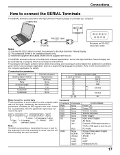
... the first command to come from the computer starts with this unit) PC mode Screen mode select (toggle) NORMAL (4:3) ZOOM FULL JUST Panasonic AUTO 17 COMPUTER RS-232C cable SERIAL 54321 9876 D-sub 9p Pin layout for RS-232C Conversion cable Notes: (1) Use the RS-232C cable to connect the computer to the High Definition Plasma Display. (2) The computers shown is controlled by a computer which...
... the first command to come from the computer starts with this unit) PC mode Screen mode select (toggle) NORMAL (4:3) ZOOM FULL JUST Panasonic AUTO 17 COMPUTER RS-232C cable SERIAL 54321 9876 D-sub 9p Pin layout for RS-232C Conversion cable Notes: (1) Use the RS-232C cable to connect the computer to the High Definition Plasma Display. (2) The computers shown is controlled by a computer which...

PT50PD3P User Guide
Page 18
Power ON/OFF and Input Signal Selection Power ON/OFF Connecting the plug to turn the High Definition Plasma Display on Power Indicator: Green To turn the set on POWER-ON Power Indicator: Green Example: The screen below is displayed for a while (setting condition is displayed. STANDBY G POWER ON TH-50PHW3 Power Indicator Push the POWER switch on the remote control to the Wall Outlet R - From the second time on or in standby mode. STANDBY G POWER ON INPUT - OSD LANGUAGE English (UK) Deutsch Fran ais...
Power ON/OFF and Input Signal Selection Power ON/OFF Connecting the plug to turn the High Definition Plasma Display on Power Indicator: Green To turn the set on POWER-ON Power Indicator: Green Example: The screen below is displayed for a while (setting condition is displayed. STANDBY G POWER ON TH-50PHW3 Power Indicator Push the POWER switch on the remote control to the Wall Outlet R - From the second time on or in standby mode. STANDBY G POWER ON INPUT - OSD LANGUAGE English (UK) Deutsch Fran ais...
PT50PD3P User Guide
Page 21
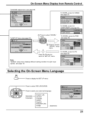
... 21 Press to "SET UP" menu. Press to select "SIGNAL" menu. On-Screen Menu Display from Remote Control To SOUND adjust menu (see page 26) SOUND NORMALIZE NORMAL AUDIO MENU BASS TREBLE BALANCE SURROUND NORMALIZE ADJUST SELECT STANDARD 0 0 0 ON RETURN To SIGNAL screen for VIDEO (see page 31) SIGNAL [ VIDEO ] 3D Y/C FILTER (NTSC) COLOR SYSTEM Panasonic AUTO (4:3) ON AUTO NORMAL To SIGNAL screen for COMPONENT (see page 32) SIGNAL [ COMPONENT ] To SET UP menu (see page 30) SET UP COMPONENT/RGB...
... 21 Press to "SET UP" menu. Press to select "SIGNAL" menu. On-Screen Menu Display from Remote Control To SOUND adjust menu (see page 26) SOUND NORMALIZE NORMAL AUDIO MENU BASS TREBLE BALANCE SURROUND NORMALIZE ADJUST SELECT STANDARD 0 0 0 ON RETURN To SIGNAL screen for VIDEO (see page 31) SIGNAL [ VIDEO ] 3D Y/C FILTER (NTSC) COLOR SYSTEM Panasonic AUTO (4:3) ON AUTO NORMAL To SIGNAL screen for COMPONENT (see page 32) SIGNAL [ COMPONENT ] To SET UP menu (see page 30) SET UP COMPONENT/RGB...
PT50PD3P User Guide
Page 22
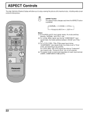
... (575i) signal input during "COMPONENT" input signal mode, the mode is set to enjoy viewing the picture at its maximum size, including wide screen cinema format picture. PC OFF TIMER PLASMA DISPLAY 22 INPUT SURROUND VOL N R PICTURE SOUND SET UP PICTURE POS. /SIZE ASPECT ASPECT ASPECT button The aspect mode changes each time the ASPECT button is memorized separately for each input terminal (VIDEO, COMPONENT, RGB and PC). NORMAL ZOOM FULL Panasonic AUTO JUST Notes: (1) During RGB and PC input signal modes, the mode switches between...
... (575i) signal input during "COMPONENT" input signal mode, the mode is set to enjoy viewing the picture at its maximum size, including wide screen cinema format picture. PC OFF TIMER PLASMA DISPLAY 22 INPUT SURROUND VOL N R PICTURE SOUND SET UP PICTURE POS. /SIZE ASPECT ASPECT ASPECT button The aspect mode changes each time the ASPECT button is memorized separately for each input terminal (VIDEO, COMPONENT, RGB and PC). NORMAL ZOOM FULL Panasonic AUTO JUST Notes: (1) During RGB and PC input signal modes, the mode switches between...
PT50PD3P User Guide
Page 24
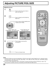
... "RGB" and "PC" input signal modes. PICTURE POS./SIZE NORMALIZE NORMAL H-POS H-SIZE V-POS V-SIZE CLOCK PHASE NORMALIZE ADJUST SELECT RETURN 3 Press to adjust screen/position (see page 23). 2 PICTURE POS. /SIZE Press to display the PICTURE POS./ SIZE menu. INPUT SURROUND VOL N R PICTURE SOUND SET UP PICTURE POS. /SIZE ASPECT PC OFF TIMER PLASMA DISPLAY R Press to select H-POS/H-SIZE/V-POS/ V-SIZE/CLOCK PHASE. Notes: (1) Adjustment details are memorized separately for different input signal formats (Adjustments for component signals are memorized for...
... "RGB" and "PC" input signal modes. PICTURE POS./SIZE NORMALIZE NORMAL H-POS H-SIZE V-POS V-SIZE CLOCK PHASE NORMALIZE ADJUST SELECT RETURN 3 Press to adjust screen/position (see page 23). 2 PICTURE POS. /SIZE Press to display the PICTURE POS./ SIZE menu. INPUT SURROUND VOL N R PICTURE SOUND SET UP PICTURE POS. /SIZE ASPECT PC OFF TIMER PLASMA DISPLAY R Press to select H-POS/H-SIZE/V-POS/ V-SIZE/CLOCK PHASE. Notes: (1) Adjustment details are memorized separately for different input signal formats (Adjustments for component signals are memorized for...
PT50PD3P User Guide
Page 26
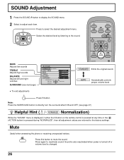
... the desired adjustment menu. INPUT SURROUND VOL N R PICTURE SOUND SET UP BASS Adjusts low sounds TREBLE Adjusts high sounds BALANCE Adjusts left and right volumes SURROUND (see page 27) Helpful Hint ( N / NORMALIZE Normalization) While the "SOUND" menu is displayed, if either the N button on the remote control is pressed at any time or the (ACTION button) is changed. 26 Press this button to the sound. AUTO Automatically controls proper volume level. • To end adjustments R Press R button Note...
... the desired adjustment menu. INPUT SURROUND VOL N R PICTURE SOUND SET UP BASS Adjusts low sounds TREBLE Adjusts high sounds BALANCE Adjusts left and right volumes SURROUND (see page 27) Helpful Hint ( N / NORMALIZE Normalization) While the "SOUND" menu is displayed, if either the N button on the remote control is pressed at any time or the (ACTION button) is changed. 26 Press this button to the sound. AUTO Automatically controls proper volume level. • To end adjustments R Press R button Note...
PT50PD3P User Guide
Page 28
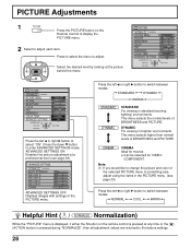
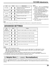
... Displays images with settings of BRIGHTNESS and PICTURE. This menu selects the normal levels of the selected PICTURE menu to something else, adjust using the items in the PICTURE menu. (see page 29). Note: (1) If you would like to switch between modes. Press to select the menu to select "ON". Press the left or right button to adjust. PICTURE NORMALIZE NORMAL PICTURE MENU PICTURE BRIGHTNESS COLOR TINT SHARPNESS COLOR TEMP ADVANCED SETTINGS NORMALIZE ADJUST...
... Displays images with settings of BRIGHTNESS and PICTURE. This menu selects the normal levels of the selected PICTURE menu to something else, adjust using the items in the PICTURE menu. (see page 29). Note: (1) If you would like to switch between modes. Press to select the menu to select "ON". Press the left or right button to adjust. PICTURE NORMALIZE NORMAL PICTURE MENU PICTURE BRIGHTNESS COLOR TINT SHARPNESS COLOR TEMP ADVANCED SETTINGS NORMALIZE ADJUST...
PT50PD3P User Guide
Page 29
... the "ADVANCED SETTINGS" menu is displayed, if either the N button on the remote control is pressed at any time or the (ACTION button) is increased with a bright picture or reduced with a dark picture. Adjust for each input mode (VIDEO, COMPONENT, RGB and PC). (4) The "TINT" setting can be used as an adjustment reference. Less More W/B LOW B Adjusts the white balance for "RGB" and "PC" input signal modes. (2) You can change when PICTURE is pressed...
... the "ADVANCED SETTINGS" menu is displayed, if either the N button on the remote control is pressed at any time or the (ACTION button) is increased with a bright picture or reduced with a dark picture. Adjust for each input mode (VIDEO, COMPONENT, RGB and PC). (4) The "TINT" setting can be used as an adjustment reference. Less More W/B LOW B Adjusts the white balance for "RGB" and "PC" input signal modes. (2) You can change when PICTURE is pressed...
PT50PD3P User Guide
Page 30
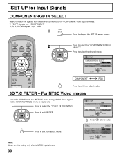
... PICTURE POS. /SIZE ASPECT COMPONENT RGB R Press to the COMPONENT/RGB input terminals. SET UP for Input Signals COMPONENT/RGB IN SELECT Select to match the signals from the source connected to exit from adjust mode. 3D Y/C FILTER - Note: When on, this setting only affects NTSC input signals. 30 SIGNAL 3D Y/C FILTER (NTSC) COLOR SYSTEM Panasonic AUTO (4:3) [ VIDEO ] ON AUTO NORMAL CHANGE SELECT RETURN For NTSC Video images Select the SIGNAL from the "SET UP" menu...
... PICTURE POS. /SIZE ASPECT COMPONENT RGB R Press to the COMPONENT/RGB input terminals. SET UP for Input Signals COMPONENT/RGB IN SELECT Select to match the signals from the source connected to exit from adjust mode. 3D Y/C FILTER - Note: When on, this setting only affects NTSC input signals. 30 SIGNAL 3D Y/C FILTER (NTSC) COLOR SYSTEM Panasonic AUTO (4:3) [ VIDEO ] ON AUTO NORMAL CHANGE SELECT RETURN For NTSC Video images Select the SIGNAL from the "SET UP" menu...

PT50PD3P User Guide
Page 33
... remain on the remote control.) No Picture Normal Sound If a signal with a cooling fan to display fixed images for extended periods of the screen may be heard from fixed image use . This is manufactured using an extremely high level of precision technology, however, sometimes some parts of time. Whirring sounds can cause a permanent after -image on the Plasma Display resulting from the display unit. Troubleshooting Before you call for service, determine the...
... remain on the remote control.) No Picture Normal Sound If a signal with a cooling fan to display fixed images for extended periods of the screen may be heard from fixed image use . This is manufactured using an extremely high level of precision technology, however, sometimes some parts of time. Whirring sounds can cause a permanent after -image on the Plasma Display resulting from the display unit. Troubleshooting Before you call for service, determine the...
PT50PD3P User Guide
Page 34
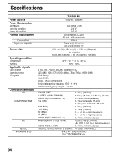
Specifications Power Source Power Consumption Normal use Stand-by condition Power off condition Plasma Display panel Contrast Ratio Brightness Capability Screen size Operating condition Temperature Humidity Applicable signals Color System Scanning format PC signals Connection terminals AV COMPONENT/RGB PC SERIAL SPEAKERS (6 Ω) TH-50PHD3 120 V AC, 50/60 Hz Max. of pixels 1,049,088 (1366 (W) × 768 (H)) [4,098 × 768 dots] 34 °F - 104 °F (0 °C - 40 °C) 20 % - 80 % NTSC, PAL...
Specifications Power Source Power Consumption Normal use Stand-by condition Power off condition Plasma Display panel Contrast Ratio Brightness Capability Screen size Operating condition Temperature Humidity Applicable signals Color System Scanning format PC signals Connection terminals AV COMPONENT/RGB PC SERIAL SPEAKERS (6 Ω) TH-50PHD3 120 V AC, 50/60 Hz Max. of pixels 1,049,088 (1366 (W) × 768 (H)) [4,098 × 768 dots] 34 °F - 104 °F (0 °C - 40 °C) 20 % - 80 % NTSC, PAL...


