

PTD6000U User Guide
Page 2
... use of uninsulated "dangerous voltage" within an equilateral triangle is intended to alert the user to persons. Do not remove the grounding pin on its bottom. If you need to at the directive 2004/108/EC, article 9(2) Panasonic Testing Center Panasonic Service Europe, a division of your Panasonic DLP™Based Projector. Do not remove Pursuant to obtain a separate 250 V power cord. This plug...
... use of uninsulated "dangerous voltage" within an equilateral triangle is intended to alert the user to persons. Do not remove the grounding pin on its bottom. If you need to at the directive 2004/108/EC, article 9(2) Panasonic Testing Center Panasonic Service Europe, a division of your Panasonic DLP™Based Projector. Do not remove Pursuant to obtain a separate 250 V power cord. This plug...

PTD6000U User Guide
Page 5
... Appendix ENGLISH - 5 Monitor Lamp indicators 28 Managing the indicated problems 28 Replacement 30 Replacing the Lamp unit 30 Replacing the Auto Cleaning Filter (ACF 31 Troubleshooting 33 Appendix 5. Adjust the image See "Menu Navigation" on page 14. Set up your projector See "Setting up 16 Projection method 16 Removing and attaching the projection lens 17 Power cord 18 Basic Operation 2. Important Information Preparation Basic Operation Getting Started Contents J Quick...
... Appendix ENGLISH - 5 Monitor Lamp indicators 28 Managing the indicated problems 28 Replacement 30 Replacing the Lamp unit 30 Replacing the Auto Cleaning Filter (ACF 31 Troubleshooting 33 Appendix 5. Adjust the image See "Menu Navigation" on page 14. Set up your projector See "Setting up 16 Projection method 16 Removing and attaching the projection lens 17 Power cord 18 Basic Operation 2. Important Information Preparation Basic Operation Getting Started Contents J Quick...

PTD6000U User Guide
Page 6
...or overheating could result. The wall outlet shall be installed near any inspection, adjustment and repair work (such as this projector in fire. Insert the power plug securely into water or let it...power cord that injury or electric shocks may result. Failure to use of a surface which are unstable. Installation work , please contact an Authorized Service Center. Continued use the projector in such cases, otherwise fire or electric shocks could result in a place which can cause fire or electric shocks. If the projector is broken, disconnect the power plug from the wall...
...or overheating could result. The wall outlet shall be installed near any inspection, adjustment and repair work (such as this projector in fire. Insert the power plug securely into water or let it...power cord that injury or electric shocks may result. Failure to use of a surface which are unstable. Installation work , please contact an Authorized Service Center. Continued use the projector in such cases, otherwise fire or electric shocks could result in a place which can cause fire or electric shocks. If the projector is broken, disconnect the power plug from the wall...

PTD6000U User Guide
Page 8
... contamination of time, disconnect the power plug from the wall outlet and remove the batteries from the remote control. Remove the used batteries in damage or injury. If dust builds up inside the projector at least once a year. Do not use chemical treated wipes when cleaning. Disconnect the power plug from the remote control promptly. Electric shocks can damage the cables, which could cause fire...
... contamination of time, disconnect the power plug from the wall outlet and remove the batteries from the remote control. Remove the used batteries in damage or injury. If dust builds up inside the projector at least once a year. Do not use chemical treated wipes when cleaning. Disconnect the power plug from the remote control promptly. Electric shocks can damage the cables, which could cause fire...

PTD6000U User Guide
Page 9
... installing the projection lens. The internal parts can occur on the screen affected by a qualified technician. See "TEMP indicator" on use In order to get the best picture quality Draw curtains or blinds over any windows and turn off any lights near an air conditioner or lighting equipment. If using the projector, close the front panel cover. Do not touch the surfaces of the set...
... installing the projection lens. The internal parts can occur on the screen affected by a qualified technician. See "TEMP indicator" on use In order to get the best picture quality Draw curtains or blinds over any windows and turn off any lights near an air conditioner or lighting equipment. If using the projector, close the front panel cover. Do not touch the surfaces of the set...

PTD6000U User Guide
Page 10
... condition and the installation environment. Change your personal registered information. The Authorized Service Center will never ask you use projectors with the adjustable feet or projection lens cover removed. The brightness of your password regularly. The lamp may explode only occasionally after the instructed lamp replacement timing. Note that in less than 22 hours, or the frequent switching on or off may...
... condition and the installation environment. Change your personal registered information. The Authorized Service Center will never ask you use projectors with the adjustable feet or projection lens cover removed. The brightness of your password regularly. The lamp may explode only occasionally after the instructed lamp replacement timing. Note that in less than 22 hours, or the frequent switching on or off may...

PTD6000U User Guide
Page 12
... exhaust port STANDBY(RED)/ ON(GREEN) LAMP TEMP FILTER Projection lens Focus ring Remote control signal receptor (page 21) Front leg adjusters Screw up/down to adjust focus, zoom and shift by the projection lens. (page 19) Navigation and ENTER buttons Navigate through the menu items with the ENTER button. (page 27) AUTO SETUP button Pressing this button while projecting an image automatically corrects the picture positioning on the screen...
... exhaust port STANDBY(RED)/ ON(GREEN) LAMP TEMP FILTER Projection lens Focus ring Remote control signal receptor (page 21) Front leg adjusters Screw up/down to adjust focus, zoom and shift by the projection lens. (page 19) Navigation and ENTER buttons Navigate through the menu items with the ENTER button. (page 27) AUTO SETUP button Pressing this button while projecting an image automatically corrects the picture positioning on the screen...

PTD6000U User Guide
Page 13
... Connect a video signals. (BNC) LAN Connect a LAN cable for network connection. (10BASE-T/100BASE-TX) About Your Projector RGB 1 IN Connect an RGB or YPBPR signals. (3, 4 or 5 wire BNC) RGB 2 IN Connect an RGB or YPBPR signals. (D-SUB 15 pin female) DVI-D IN Connect a single link DVI-D signals. ENGLISH - 13 Air intake port Air intake port POWER button Switch the projector on the POWER button of the projector body that is located near the terminals before using the control buttons...
... Connect a video signals. (BNC) LAN Connect a LAN cable for network connection. (10BASE-T/100BASE-TX) About Your Projector RGB 1 IN Connect an RGB or YPBPR signals. (3, 4 or 5 wire BNC) RGB 2 IN Connect an RGB or YPBPR signals. (D-SUB 15 pin female) DVI-D IN Connect a single link DVI-D signals. ENGLISH - 13 Air intake port Air intake port POWER button Switch the projector on the POWER button of the projector body that is located near the terminals before using the control buttons...

PTD6000U User Guide
Page 14
... button while projecting an image automatically corrects the picture positioning on screen indications. (page 22) TEST PATTERN button Displays the test pattern. (page 22) Numeric (0 - 9) buttons Enter ID number of the remote control, adjustment values of the remote control. (page 15) B Top view Remote control signal emitters Bottom view Remote control wired terminal A Battery compartment 1.Press the tab and lift up the cover. 2.Insert the batteries according to modify or disassemble the remote control. ENGLISH - 14 POWER...
... button while projecting an image automatically corrects the picture positioning on screen indications. (page 22) TEST PATTERN button Displays the test pattern. (page 22) Numeric (0 - 9) buttons Enter ID number of the remote control, adjustment values of the remote control. (page 15) B Top view Remote control signal emitters Bottom view Remote control wired terminal A Battery compartment 1.Press the tab and lift up the cover. 2.Insert the batteries according to modify or disassemble the remote control. ENGLISH - 14 POWER...

PTD6000U User Guide
Page 15
... number range: 01 - 64 About Your Projector J Using a wired remote control When multiple projectors are connected as part of the system, connect to units with a single remote control through the REMOTE 1 IN/OUT terminal. When the batteries are susceptible to match the intended projector. Displays the projector ID number on the remote control can be assigned a unique 2 digits ID number, and the remote control 2 digits ID number must be set to outside light. ENGLISH...
... number range: 01 - 64 About Your Projector J Using a wired remote control When multiple projectors are connected as part of the system, connect to units with a single remote control through the REMOTE 1 IN/OUT terminal. When the batteries are susceptible to match the intended projector. Displays the projector ID number on the remote control can be assigned a unique 2 digits ID number, and the remote control 2 digits ID number must be set to outside light. ENGLISH...

PTD6000U User Guide
Page 16
... in PROJECTOR SETUP menu on the functional instructions in the projector, J Setting on a desk/floor and J Setting on a desk/floor and projecting from front projecting from rear INSTALLATION: FRONT/FLOOR COOLING CONDITION: FLOOR SETTING J Mounting on the ceiling and projecting from front INSTALLATION: REAR/FLOOR COOLING CONDITION: FLOOR SETTING J Mounting on top of another projector. • Do not cover the ventilation openings or...
... in PROJECTOR SETUP menu on the functional instructions in the projector, J Setting on a desk/floor and J Setting on a desk/floor and projecting from front projecting from rear INSTALLATION: FRONT/FLOOR COOLING CONDITION: FLOOR SETTING J Mounting on the ceiling and projecting from front INSTALLATION: REAR/FLOOR COOLING CONDITION: FLOOR SETTING J Mounting on top of another projector. • Do not cover the ventilation openings or...

PTD6000U User Guide
Page 19
... before switch on the screen. Press F G I H to adjust the position of the projector. NOTE: • The setup screen will flash in the screen. Adjust the vertical tilt of the lens. 2. Press the POWER ON button The power indicator lamp illuminates in PROJECTOR SETUP menu. 3. Readjust the focus. 8. Press FOCUS, ZOOM or SHIFT button Remote control buttons to catch your fingers between the lens and shroud when shifting the lens. Connect the supplied power cord...
... before switch on the screen. Press F G I H to adjust the position of the projector. NOTE: • The setup screen will flash in the screen. Adjust the vertical tilt of the lens. 2. Press the POWER ON button The power indicator lamp illuminates in PROJECTOR SETUP menu. 3. Readjust the focus. 8. Press FOCUS, ZOOM or SHIFT button Remote control buttons to catch your fingers between the lens and shroud when shifting the lens. Connect the supplied power cord...

PTD6000U User Guide
Page 21
... automatic adjustment. • Even for an RGB signal for which automatic setup is possible, if automatic setup is performed while moving images are clear in white and black contrast when the system is in POSITION menu. • If an image with a bright white frame at the outermost periphery containing characters etc. Input an analogue RGB image signal. 2. Displays a message "PROGRESS". 4. The operating range may not be effective with a translucent screen. When...
... automatic adjustment. • Even for an RGB signal for which automatic setup is possible, if automatic setup is performed while moving images are clear in white and black contrast when the system is in POSITION menu. • If an image with a bright white frame at the outermost periphery containing characters etc. Input an analogue RGB image signal. 2. Displays a message "PROGRESS". 4. The operating range may not be effective with a translucent screen. When...
PTD6000U User Guide
Page 23
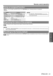
... the image. NOTE: • See FUNCTION in PROJECTOR SETUP menu and each corresponding menu items of the functional instructions that is in the provided CD-ROM. SYSTEM SELECTOR Switches the SYSTEM SELECTOR options. Resetting to the FUNCTION button. SIDE BY SIDE Start the SIDE BY SIDE mode. SUB MEMORY LIST Display the assigned SUB MEMORY LIST. Basic Operation ENGLISH - 23 Remote control operation Using an...
... the image. NOTE: • See FUNCTION in PROJECTOR SETUP menu and each corresponding menu items of the functional instructions that is in the provided CD-ROM. SYSTEM SELECTOR Switches the SYSTEM SELECTOR options. Resetting to the FUNCTION button. SIDE BY SIDE Start the SIDE BY SIDE mode. SUB MEMORY LIST Display the assigned SUB MEMORY LIST. Basic Operation ENGLISH - 23 Remote control operation Using an...

PTD6000U User Guide
Page 25
DISPLAY OPTION COLOR MATCHING OFF 3 COLORS 7 COLORS MEASURED COLOR CORRECTION OFF USER CONTRAST MODE NORMAL HIGH SCREEN SETTING SCREEN FORMAT 16:10 16:9 4:3 SCREEN POSITION AUTO SIGNAL ON AUTO SETUP DEFAULT USER DVI-D IN OFF WIDE DVI EDID EDID3 EDID1 EDID2(PC) DVI SIGNAL LEVEL 0-255:PC 16-235 SDI IN 64-940 4-1019 ON-SCREEN DISPLAY OSD POSITION 1 2 3 4 5 6 7 8 9 OSD DESIGN 1 2 3 4 5 6 OSD MEMORY ON OFF INPUT GUIDE ON OFF WARNING MESSAGE ON OFF BACK COLOR BLACK LOGO1 BLUE LOGO2 STARTUP LOGO LOGO2 LOGO1 NONE FREEZE SIDE...
DISPLAY OPTION COLOR MATCHING OFF 3 COLORS 7 COLORS MEASURED COLOR CORRECTION OFF USER CONTRAST MODE NORMAL HIGH SCREEN SETTING SCREEN FORMAT 16:10 16:9 4:3 SCREEN POSITION AUTO SIGNAL ON AUTO SETUP DEFAULT USER DVI-D IN OFF WIDE DVI EDID EDID3 EDID1 EDID2(PC) DVI SIGNAL LEVEL 0-255:PC 16-235 SDI IN 64-940 4-1019 ON-SCREEN DISPLAY OSD POSITION 1 2 3 4 5 6 7 8 9 OSD DESIGN 1 2 3 4 5 6 OSD MEMORY ON OFF INPUT GUIDE ON OFF WARNING MESSAGE ON OFF BACK COLOR BLACK LOGO1 BLUE LOGO2 STARTUP LOGO LOGO2 LOGO1 NONE FREEZE SIDE...
PTD6000U User Guide
Page 29
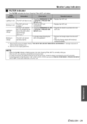
... will be shorter. message and power off with the indicator blinking in red • Check the REMAINING FILTER • Replace the ACF unit. Lamp indication Information Check point Remedial measure Lighting in red. *2. 200 hours is the roughly guided time. NOTE: • When the FILTER indicator is flashing green, the Auto Cleaning Filter (ACF) is normally rolling up. • When the ACF unit...
... will be shorter. message and power off with the indicator blinking in red • Check the REMAINING FILTER • Replace the ACF unit. Lamp indication Information Check point Remedial measure Lighting in red. *2. 200 hours is the roughly guided time. NOTE: • When the FILTER indicator is flashing green, the Auto Cleaning Filter (ACF) is normally rolling up. • When the ACF unit...

PTD6000U User Guide
Page 33
... flashes. The control buttons of the operation range. The power cord may be connected. The lens may not be dirty. COLOR or TINT adjustment may be incorrect. CONTROL PANEL of CONTROL DEVICE SETUP in the provided CD-ROM. Picture from a computer DVI-D graphic board does not appear. A signal which is connected to the projector may be restarted after switching DVI-D IN setting in use. CD-ROM: See the functional instructions in SECURITY menu is disabled...
... flashes. The control buttons of the operation range. The power cord may be connected. The lens may not be dirty. COLOR or TINT adjustment may be incorrect. CONTROL PANEL of CONTROL DEVICE SETUP in the provided CD-ROM. Picture from a computer DVI-D graphic board does not appear. A signal which is connected to the projector may be restarted after switching DVI-D IN setting in use. CD-ROM: See the functional instructions in SECURITY menu is disabled...

PTD6000U User Guide
Page 36
...SYNC, VD terminals are not compliant with the projector. Technical Information Specifications Power supply Power consumption Amps DLP™ chip Panel size (diagonal) Aspect ratio Display method Pixels Lens Motorized zoom Motorized focus Lamp Luminosity*2 Operating environment VIDEO/S-VIDEO RGB Scanning frequency*3 DVI-D YPBPR Color system Projection size Screen aspect ratio Installation Contrast...for the projectors that "L" follows in model number. WUXGA (non interlace) Dot clock frequency: 25 - 162 MHz WUXGA signal is set to HIGH) Appendix ENGLISH - 36 UHM lamp (300 W)...
...SYNC, VD terminals are not compliant with the projector. Technical Information Specifications Power supply Power consumption Amps DLP™ chip Panel size (diagonal) Aspect ratio Display method Pixels Lens Motorized zoom Motorized focus Lamp Luminosity*2 Operating environment VIDEO/S-VIDEO RGB Scanning frequency*3 DVI-D YPBPR Color system Projection size Screen aspect ratio Installation Contrast...for the projectors that "L" follows in model number. WUXGA (non interlace) Dot clock frequency: 25 - 162 MHz WUXGA signal is set to HIGH) Appendix ENGLISH - 36 UHM lamp (300 W)...

PTD6000U User Guide
Page 37
...15p (female) RGB signal 0.7 V [p-p], 75 Ω (G-SYNC: 1.0 V [p-p], 75 Ω) • HD/SYNC: TTL high impedance, automatic positive/negative polarity compatible • VD: TTL high impedance, automatic positive/negative polarity compatible YPBPR signal • Y: 1.0 V [p-p] Synchronisation signal included • PBPR: 0.7 V [p-p], 75 Ω 1 set, DVI-D 24-pin (Single link), DVI 1.0 compatible, HDCP compatible SERIAL 1 set, D-sub 9-pin (female), RS-232C compatible, computer control use REMOTE1 1 set, M3 pin jack, wired remote control use, multiple connection use Cabinet REMOTE2...
...15p (female) RGB signal 0.7 V [p-p], 75 Ω (G-SYNC: 1.0 V [p-p], 75 Ω) • HD/SYNC: TTL high impedance, automatic positive/negative polarity compatible • VD: TTL high impedance, automatic positive/negative polarity compatible YPBPR signal • Y: 1.0 V [p-p] Synchronisation signal included • PBPR: 0.7 V [p-p], 75 Ω 1 set, DVI-D 24-pin (Single link), DVI 1.0 compatible, HDCP compatible SERIAL 1 set, D-sub 9-pin (female), RS-232C compatible, computer control use REMOTE1 1 set, M3 pin jack, wired remote control use, multiple connection use Cabinet REMOTE2...

PTD6000U User Guide
Page 39
... 11 Air exhaust port 12 Air intake port 13 ASPECT Remote control button 14 Remote control function 22 Auto Cleaning Filter (ACF 13 AUTO SETUP Control panel button 12 Remote control button 14 Remote control function 21 B Battery 11 Compartment 14 Burglar hook port 12 C CD-ROM 11 Accessories 11 Menu 24 D DEFAULT Remote control button 14 Remote control function 23 Dimensions 38 Direct power off 20 DISPLAY LANGUAGE 24 DVI-D Control panel button 12 Remote control button 14 Terminal 13 E ENTER Control panel button 12 Menu navigation 27 Remote control button 14 F FILTER...
... 11 Air exhaust port 12 Air intake port 13 ASPECT Remote control button 14 Remote control function 22 Auto Cleaning Filter (ACF 13 AUTO SETUP Control panel button 12 Remote control button 14 Remote control function 21 B Battery 11 Compartment 14 Burglar hook port 12 C CD-ROM 11 Accessories 11 Menu 24 D DEFAULT Remote control button 14 Remote control function 23 Dimensions 38 Direct power off 20 DISPLAY LANGUAGE 24 DVI-D Control panel button 12 Remote control button 14 Terminal 13 E ENTER Control panel button 12 Menu navigation 27 Remote control button 14 F FILTER...


