

Brochure
Page 1
... In Audio In (L/R) Audio Out (L/R) M3 Jack x 1 (Shared with PC In) Mini D-sub 15-pin x 1, Plug & Play (VESA DDC 2B) M3 Jack x 1 (Shared with DVI-D In) RCA Pin Jack x 2 Wireless I Effective Display Area 5.31134) 2 3157.71 + it 20Lcas = U Approx. 730 W Approx. 630 W Power off Condition Approx. 0.3 W Approx. 0.2 W Stand-by Condition Approx. 0.5 W Approx. 0.4 W SOUND MECHANICAL Internal Speaker Output Dimensions (W x Fix 0) Weight Cabinet Color 8 0 20 W [10W. Measured in "Dynamic" picture mode using a white signal...
... In Audio In (L/R) Audio Out (L/R) M3 Jack x 1 (Shared with PC In) Mini D-sub 15-pin x 1, Plug & Play (VESA DDC 2B) M3 Jack x 1 (Shared with DVI-D In) RCA Pin Jack x 2 Wireless I Effective Display Area 5.31134) 2 3157.71 + it 20Lcas = U Approx. 730 W Approx. 630 W Power off Condition Approx. 0.3 W Approx. 0.2 W Stand-by Condition Approx. 0.5 W Approx. 0.4 W SOUND MECHANICAL Internal Speaker Output Dimensions (W x Fix 0) Weight Cabinet Color 8 0 20 W [10W. Measured in "Dynamic" picture mode using a white signal...
Brochure
Page 2
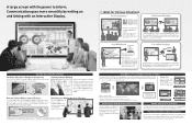
...: http://pa na sonic.nethrodisplaysipro d ucts/pbseries/function.html * The optional ET-WM200U Wireless Module is required for wireless connection. * Application software for graphic design and other situations where presentations are optional. *The "Whiteboard Software for Instant Use There's no need to display motion pictures in a remote location can be seen by wiping with the Marker function is also minimized to...
...: http://pa na sonic.nethrodisplaysipro d ucts/pbseries/function.html * The optional ET-WM200U Wireless Module is required for wireless connection. * Application software for graphic design and other situations where presentations are optional. *The "Whiteboard Software for Instant Use There's no need to display motion pictures in a remote location can be seen by wiping with the Marker function is also minimized to...

Operating Instructions
Page 2
...://panasonic.net Table of Contents Important Safety Notice 3 Safety Precautions 4 Accessories 7 Accessories Supply 7 Remote Control Batteries 8 Connections 9 AC cord connection and ¿xing, cable ¿xing 9 Video equipment connection 10 AUDIO OUT Terminals connection 11 VIDEO and COMPONENT / RGB IN connection ...11 HDMI connection 12 DVI-D IN connection 12 PC Input Terminals connection 13 SERIAL Terminals connection 14 Power On / Off 15 Selecting the input signal 17 Basic Controls 18 ASPECT Controls 20 Digital Zoom 21 On-Screen Menu Displays 22 Adjusting Pos./Size...
...://panasonic.net Table of Contents Important Safety Notice 3 Safety Precautions 4 Accessories 7 Accessories Supply 7 Remote Control Batteries 8 Connections 9 AC cord connection and ¿xing, cable ¿xing 9 Video equipment connection 10 AUDIO OUT Terminals connection 11 VIDEO and COMPONENT / RGB IN connection ...11 HDMI connection 12 DVI-D IN connection 12 PC Input Terminals connection 13 SERIAL Terminals connection 14 Power On / Off 15 Selecting the input signal 17 Basic Controls 18 ASPECT Controls 20 Digital Zoom 21 On-Screen Menu Displays 22 Adjusting Pos./Size...
Operating Instructions
Page 3
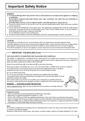
... unable to replace the fuse. Refer servicing to wobble or cause interference such as lighted candles, should be used with this appliance near sources of strong electromagnetic ¿elds. This plug will only ¿t an earthing-type power outlet. Open the fuse compartment with the input signals could cause the picture and sound to quali¿ed service personnel. 3) Do not remove the...
... unable to replace the fuse. Refer servicing to wobble or cause interference such as lighted candles, should be used with this appliance near sources of strong electromagnetic ¿elds. This plug will only ¿t an earthing-type power outlet. Open the fuse compartment with the input signals could cause the picture and sound to quali¿ed service personnel. 3) Do not remove the...

Operating Instructions
Page 4
... Setup This Plasma Display is for use only with the following accessories are manufactured by Panasonic Corporation.) • Pedestal TY-ST85P12 (for TH-85PB1E), TY-ST103PF9 (for TH-103PB1E) • Mobile stand for Display TY-ST85PB1 (for TH-85PB1E) • Floor stand TY-ST85PF12 (for TH-85PB1E) • Wall-hanging bracket (vertical TY-WK85PV12 (for TH-85PB1E), TY-WK103PV9 (for TH-103PB1E) • Ceiling-hanging bracket TY-CE85PS12 (for TH...
... Setup This Plasma Display is for use only with the following accessories are manufactured by Panasonic Corporation.) • Pedestal TY-ST85P12 (for TH-85PB1E), TY-ST103PF9 (for TH-103PB1E) • Mobile stand for Display TY-ST85PB1 (for TH-85PB1E) • Floor stand TY-ST85PF12 (for TH-85PB1E) • Wall-hanging bracket (vertical TY-WK85PV12 (for TH-85PB1E), TY-WK103PV9 (for TH-103PB1E) • Ceiling-hanging bracket TY-CE85PS12 (for TH...
Operating Instructions
Page 5
... the cabinet becomes damages, disconnect the power supply plug immediately. • A short circuit may damage the power cable. Contact your local Panasonic dealer. Safety Precautions When installing the Plasma Display vertically; Turn down the power switch for any modi¿cations to overheat, which could cause ¿re. Do not remove the cover or modify it repaired at all times. An apparatus with CLASS I construction shall...
... the cabinet becomes damages, disconnect the power supply plug immediately. • A short circuit may damage the power cable. Contact your local Panasonic dealer. Safety Precautions When installing the Plasma Display vertically; Turn down the power switch for any modi¿cations to overheat, which could cause ¿re. Do not remove the cover or modify it repaired at all times. An apparatus with CLASS I construction shall...
Operating Instructions
Page 11
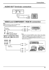
... Computer DVD Player RGB Camcorder 11 RCA-BNC Adapter plug VIDEO OUT L AUDIO R OUT VCR AUDIO L-R: Shared with VIDEO and COMPONENT/RGB IN Notes: • Change the "Component/RGB-in select" setting in audio equipment VIDEO and COMPONENT / RGB IN connection Note: Additional equipment, cables and adapter plugs shown are not supplied with this set. AUDIO OUT Terminals connection Connections Stereophonic sound code line-in the "Setup" menu to "Component" (when Component signal connection) or "RGB" (when RGB signal connection...
... Computer DVD Player RGB Camcorder 11 RCA-BNC Adapter plug VIDEO OUT L AUDIO R OUT VCR AUDIO L-R: Shared with VIDEO and COMPONENT/RGB IN Notes: • Change the "Component/RGB-in select" setting in audio equipment VIDEO and COMPONENT / RGB IN connection Note: Additional equipment, cables and adapter plugs shown are not supplied with this set. AUDIO OUT Terminals connection Connections Stereophonic sound code line-in the "Setup" menu to "Component" (when Component signal connection) or "RGB" (when RGB signal connection...
Operating Instructions
Page 15
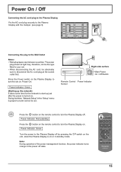
... Power Indicator: Green Turn the power to turn the set . switch on : Power-On. Power Indicator: Red (standby) Press the button on the remote control to the Plasma Display off . The power plug shown at the socket outlet ¿rst. Right side surface Main Power On / Off Switch Remote Control Power Indicator Sensor Press the button on . Fix the AC cord plug securely to the Plasma Display with the clamper. (see page 9) Connecting the plug to the Plasma Display. During that time, "Network Setup" in the "Setup" menu...
... Power Indicator: Green Turn the power to turn the set . switch on : Power-On. Power Indicator: Red (standby) Press the button on the remote control to the Plasma Display off . The power plug shown at the socket outlet ¿rst. Right side surface Main Power On / Off Switch Remote Control Power Indicator Sensor Press the button on . Fix the AC cord plug securely to the Plasma Display with the clamper. (see page 9) Connecting the plug to the Plasma Display. During that time, "Network Setup" in the "Setup" menu...
Operating Instructions
Page 17
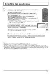
... input terminals is installed: PC NETWORK SLOT INPUT A SLOT INPUT B VIDEO COMPONENT HDMI DVI SLOT INPUT A, SLOT INPUT B: Dual input terminal in Terminal Board. When a Terminal Board with the Plasma Display is installed, "Non-Compatible Function Board" is kept on the unit. • Outputs the sound as set in "Audio input select" in the Options menu. (see page 57) • Select to match the signals from the equipment which has been connected to the Plasma Display. DVI: DVI input terminal in DVI...
... input terminals is installed: PC NETWORK SLOT INPUT A SLOT INPUT B VIDEO COMPONENT HDMI DVI SLOT INPUT A, SLOT INPUT B: Dual input terminal in Terminal Board. When a Terminal Board with the Plasma Display is installed, "Non-Compatible Function Board" is kept on the unit. • Outputs the sound as set in "Audio input select" in the Options menu. (see page 57) • Select to match the signals from the equipment which has been connected to the Plasma Display. DVI: DVI input terminal in DVI...
Operating Instructions
Page 19
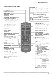
... again to change the ECO MODE setup status. (see page 40) FUNCTION buttons (FUNCTION) (see page 42) Basic Controls OFF TIMER button The Plasma Display can be plugged into the wall outlet and turned on at the power switch (see page 34) 4 Off timer The off timer indicator is displayed only when the off timer cancelled) each time the button is cancelled if a power interruption occurs. Press this button to previous menu screen. Sound is...
... again to change the ECO MODE setup status. (see page 40) FUNCTION buttons (FUNCTION) (see page 42) Basic Controls OFF TIMER button The Plasma Display can be plugged into the wall outlet and turned on at the power switch (see page 34) 4 Off timer The off timer indicator is displayed only when the off timer cancelled) each time the button is cancelled if a power interruption occurs. Press this button to previous menu screen. Sound is...
Operating Instructions
Page 23
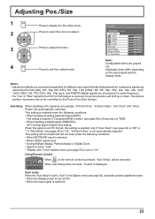
... Scan" (see page 24) is "Off" or "1:1 Pixel Mode" (see page 25) is "RGB". • When inputting a digital signal (HDMI/DVI): A PC format signal enables this setting. When Auto Setup does not work under the following conditions: • When NETWORK input is selected. • When VIDEO signal input • During Multiple display, Portrait display or Digital Zoom. • Aspect is set to "Just" • "Display size" in the Options menu (see page 53) is set to "Auto...
... Scan" (see page 24) is "Off" or "1:1 Pixel Mode" (see page 25) is "RGB". • When inputting a digital signal (HDMI/DVI): A PC format signal enables this setting. When Auto Setup does not work under the following conditions: • When NETWORK input is selected. • When VIDEO signal input • During Multiple display, Portrait display or Digital Zoom. • Aspect is set to "Just" • "Display size" in the Options menu (see page 53) is set to "Auto...

Operating Instructions
Page 24
..../Size manually. V-Size Adjust the vertical size. V-Pos Adjust the vertical position. In such case, switch to "On" in the Options menu, this happens, adjust so that any such noise is displayed. Adjusting Pos./Size H-Pos Notes: • If the dot clock frequency of alignment may results in correct Auto Setup. • Auto Setup does not work when a cropped or dark image is input. Dot Clock (During Component/PC input signal) Periodic striped pattern...
..../Size manually. V-Size Adjust the vertical size. V-Pos Adjust the vertical position. In such case, switch to "On" in the Options menu, this happens, adjust so that any such noise is displayed. Adjusting Pos./Size H-Pos Notes: • If the dot clock frequency of alignment may results in correct Auto Setup. • Auto Setup does not work when a cropped or dark image is input. Dot Clock (During Component/PC input signal) Periodic striped pattern...

Operating Instructions
Page 34
... dual input terminals is installed, "SLOT INPUT" is Off displayed as follows. Touch Only: Contact-type Touch Pen Touch & Remote: Contact-type Touch Pen and remote pointer SLOT INPUT - Pos./Size menu Picture menu Setup menu Signal Extended life settings MULTI DISPLAY Setup Portrait Setup Options menu ASPECT Controls 1:1 Pixel Mode: On Over scan: Off Picture Mode: Fixed to "Normal" (see page 21) • When using the electronic pen, adjust "Pos./Size" so that is displayed in "Setup" menu and press button.
... dual input terminals is installed, "SLOT INPUT" is Off displayed as follows. Touch Only: Contact-type Touch Pen Touch & Remote: Contact-type Touch Pen and remote pointer SLOT INPUT - Pos./Size menu Picture menu Setup menu Signal Extended life settings MULTI DISPLAY Setup Portrait Setup Options menu ASPECT Controls 1:1 Pixel Mode: On Over scan: Off Picture Mode: Fixed to "Normal" (see page 21) • When using the electronic pen, adjust "Pos./Size" so that is displayed in "Setup" menu and press button.
Operating Instructions
Page 40
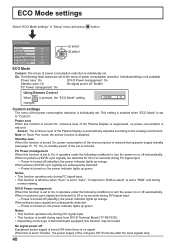
... Using Remote Control When is pressed, the "ECO Mode" setting ECO Mode On changes. the power indicator lights up orange. ECO Mode settings ECO Mode Power save Standby save : On No signal power off (standby); On: The following ¿xed values are subsequently detected: ĺ Power is individually set. the power indicator lights up green. Power save When this function may be invalid. Custom settings The menu of the Plasma Display is suppressed, so power consumption is reduced. When pictures (sync signal...
... Using Remote Control When is pressed, the "ECO Mode" setting ECO Mode On changes. the power indicator lights up orange. ECO Mode settings ECO Mode Power save Standby save : On No signal power off (standby); On: The following ¿xed values are subsequently detected: ĺ Power is individually set. the power indicator lights up green. Power save When this function may be invalid. Custom settings The menu of the Plasma Display is suppressed, so power consumption is reduced. When pictures (sync signal...

Operating Instructions
Page 42
... "Network Setup" menu is pressed. To exit this mode, press any button. • Function Button Guide The function display setting for the FUNCTION button is installed. INPUT (NETWORK) Simply press to "Operating Instructions, Network Operations" and the instruction manual of "Wireless Manager" in "Setup" menu and press button. AV Mute Mutes the audio and video. Scrolling bar Activates the "Scrolling bar only" screensaver. After 15 minutes, the display enters standby mode. To exit this mode, press button. The list...
... "Network Setup" menu is pressed. To exit this mode, press any button. • Function Button Guide The function display setting for the FUNCTION button is installed. INPUT (NETWORK) Simply press to "Operating Instructions, Network Operations" and the instruction manual of "Wireless Manager" in "Setup" menu and press button. AV Mute Mutes the audio and video. Scrolling bar Activates the "Scrolling bar only" screensaver. After 15 minutes, the display enters standby mode. To exit this mode, press button. The list...
Operating Instructions
Page 48
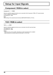
..." Notes: • Selection may not be possible, depending on which optional board is installed. • Make setting of the selected input terminal (COMPONENT/RGB IN or PC IN). Setup for Input Signals Component / RGB-in select YUV RGB Select to match the signals from the source connected to the DVI input terminals. YUV / RGB-in select Component RGB Select to match the...
..." Notes: • Selection may not be possible, depending on which optional board is installed. • Make setting of the selected input terminal (COMPONENT/RGB IN or PC IN). Setup for Input Signals Component / RGB-in select YUV RGB Select to match the signals from the source connected to the DVI input terminals. YUV / RGB-in select Component RGB Select to match the...

Operating Instructions
Page 49
..." input signal. • XGA Mode This menu is displayed when the input signal is not stable, turn the setting to suit the input signal for each adjustment (such as movie pictures, which are recorded at 24 frames per second. To display PAL60 signal, select "Auto" or "PAL". Switch the setting to "Off". Setup for Input Signals Signal menu Notes: • "Signal" setup menu displays a different setting condition for better display depends on the input signal type, an optional Terminal Board may in "Setup" menu...
..." input signal. • XGA Mode This menu is displayed when the input signal is not stable, turn the setting to suit the input signal for each adjustment (such as movie pictures, which are recorded at 24 frames per second. To display PAL60 signal, select "Auto" or "PAL". Switch the setting to "Off". Setup for Input Signals Signal menu Notes: • "Signal" setup menu displays a different setting condition for better display depends on the input signal type, an optional Terminal Board may in "Setup" menu...

Operating Instructions
Page 52
... INPUT*1 VIDEO COMPONENT*2 HDMI DVI PC NETWORK *1 "SLOT INPUT" is displayed when an optional Terminal Board is "Off". Options 1/3 Weekly Command Timer Audio input select Input Search Onscreen display On Initial input Off Initial VOL level Off 0 Maximum VOL level Off 0 Input lock Off Button lock Off Remocon User level Off 3 Press to adjust the maximum volume. Slot power O f f Power On Screen Delay Off Clock Display Off All Aspect Off Auto Setup Manual Rotate Off Advanced Motion Resolution On Power...
... INPUT*1 VIDEO COMPONENT*2 HDMI DVI PC NETWORK *1 "SLOT INPUT" is displayed when an optional Terminal Board is "Off". Options 1/3 Weekly Command Timer Audio input select Input Search Onscreen display On Initial input Off Initial VOL level Off 0 Maximum VOL level Off 0 Input lock Off Button lock Off Remocon User level Off 3 Press to adjust the maximum volume. Slot power O f f Power On Screen Delay Off Clock Display Off All Aspect Off Auto Setup Manual Rotate Off Advanced Motion Resolution On Power...
Operating Instructions
Page 53
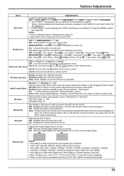
...may be used in power On. (Power Indicator : green) Note: When using ID remote control. Options Adjustments Item Input lock Button lock Adjustments Locks the input switch operation. About the setting method, please refer to set , the Off-timer is installed, "SLOT INPUT A" and "SLOT INPUT B" are as follows; Off: Disables ID remote control functions. MENU&ENTER: Locks MENU and ENTER/ buttons on screen. User3:Locks all the button on remote control. Off: Disables external control by the ID. Adjusts the image display size on the remote control. Off: Press...
...may be used in power On. (Power Indicator : green) Note: When using ID remote control. Options Adjustments Item Input lock Button lock Adjustments Locks the input switch operation. About the setting method, please refer to set , the Off-timer is installed, "SLOT INPUT A" and "SLOT INPUT B" are as follows; Off: Disables ID remote control functions. MENU&ENTER: Locks MENU and ENTER/ buttons on screen. User3:Locks all the button on remote control. Off: Disables external control by the ID. Adjusts the image display size on the remote control. Off: Press...

Operating Instructions
Page 59
.../Volume setting (Check by pressing the power switch or stand-by any problems in the Setup menu. Areas at minimum level (see page 26, 27) Normal Sound Colour system (see page 40, 43) Power indicator is displayed. There is not a malfunction. This Plasma Display uses special image processing. I use with minimal movements are shown for the picture to "On (Enable)". (see page 49) No remote control operations can hear sounds coming...
.../Volume setting (Check by pressing the power switch or stand-by any problems in the Setup menu. Areas at minimum level (see page 26, 27) Normal Sound Colour system (see page 40, 43) Power indicator is displayed. There is not a malfunction. This Plasma Display uses special image processing. I use with minimal movements are shown for the picture to "On (Enable)". (see page 49) No remote control operations can hear sounds coming...


