

Plasma Display
Page 1
Before connecting, operating or adjusting this manual for future reference. TH-37PHD8UK TH-42PHD8UK TH-50PHD8UK TH-37PWD8 The illustration shown is an image. Operating Instructions Progressive Wide Plasma Display Model No. Please keep this product, please read these instructions completely. English TQBC2026 TH-37PWD8UK TH-42PWD8UK TH-37PWD8 High Definition Plasma Display Model No.
Before connecting, operating or adjusting this manual for future reference. TH-37PHD8UK TH-42PHD8UK TH-50PHD8UK TH-37PWD8 The illustration shown is an image. Operating Instructions Progressive Wide Plasma Display Model No. Please keep this product, please read these instructions completely. English TQBC2026 TH-37PWD8UK TH-42PWD8UK TH-37PWD8 High Definition Plasma Display Model No.

Plasma Display
Page 4
... Supplied 8 Remote Control Batteries 8 Connections 9 PC Input Terminals connection 10 SERIAL Terminals connection 11 AV & COMPONENT connection 12 RGB signal (R, G, B, HD, VD 12 Power ON / OFF 13 Basic Controls 14 On-Screen Menu Displays 16 Initial selections 18 Selecting the input signal 18 Selecting the On-Screen Menu Language 18 ASPECT Controls 19 Adjusting POS. /SIZE 20 MULTI PIP 21 Advanced PIP 22 PICTURE Adjustments 23 ADVANCED SETTINGS 24 SOUND Adjustment 25 MUTE 25 Digital Zoom 26 PRESENT TIME SETUP / SET UP TIMER 27...
... Supplied 8 Remote Control Batteries 8 Connections 9 PC Input Terminals connection 10 SERIAL Terminals connection 11 AV & COMPONENT connection 12 RGB signal (R, G, B, HD, VD 12 Power ON / OFF 13 Basic Controls 14 On-Screen Menu Displays 16 Initial selections 18 Selecting the input signal 18 Selecting the On-Screen Menu Language 18 ASPECT Controls 19 Adjusting POS. /SIZE 20 MULTI PIP 21 Advanced PIP 22 PICTURE Adjustments 23 ADVANCED SETTINGS 24 SOUND Adjustment 25 MUTE 25 Digital Zoom 26 PRESENT TIME SETUP / SET UP TIMER 27...

Plasma Display
Page 5
...: Pursuant to radio or television reception, which can be displayed for an extended period, as this monitor not expressly approved by one or more of still pictures include logos, video games, computer images, teletext and images displayed in accordance with the instructions, may cause harmful interference to be determined by turning the equipment off and on the Plasma Display. FCC Declaration of the...
...: Pursuant to radio or television reception, which can be displayed for an extended period, as this monitor not expressly approved by one or more of still pictures include logos, video games, computer images, teletext and images displayed in accordance with the instructions, may cause harmful interference to be determined by turning the equipment off and on the Plasma Display. FCC Declaration of the...
Plasma Display
Page 6
...-FB7SD • HD-SDI Terminal Board TY-FB7HD • HDMI Terminal Board TY-FB8HM • Wireless Presentation Board TY-FB7WPU • Touch Panel TY-TP42P8-S (TH-42PWD8UK, TH-42PHD8UK), TY-TP50P8-S (TH-50PHD8UK) Always be displayed for use only with the following accessories are blocked. When using the Plasma Display Do not bring your Plasma Display. Clean the power cable regularly to prevent it may...
...-FB7SD • HD-SDI Terminal Board TY-FB7HD • HDMI Terminal Board TY-FB8HM • Wireless Presentation Board TY-FB7WPU • Touch Panel TY-TP42P8-S (TH-42PWD8UK, TH-42PHD8UK), TY-TP50P8-S (TH-50PHD8UK) Always be displayed for use only with the following accessories are blocked. When using the Plasma Display Do not bring your Plasma Display. Clean the power cable regularly to prevent it may...

Plasma Display
Page 7
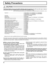
... inside the Plasma Display, please consult an Authorized Service Center. Use this cloth to wipe the cabinet, and then wipe it repaired at the rear. When disconnecting the power cable, hold the plug, not the cable. • Do not make any objects on top of the cabinet surface may be made from the Plasma Display, unplug the power cord immediately. • Continuous use If a problem occurs...
... inside the Plasma Display, please consult an Authorized Service Center. Use this cloth to wipe the cabinet, and then wipe it repaired at the rear. When disconnecting the power cable, hold the plug, not the cable. • Do not make any objects on top of the cabinet surface may be made from the Plasma Display, unplug the power cord immediately. • Continuous use If a problem occurs...
Plasma Display
Page 8
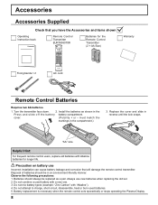
... compartment. Battery replacement is necessary when the remote control acts sporadically or stops operating the Plasma Display. 8 must match the markings in reverse until the lock snaps. Helpful Hint: For frequent remote control users, replace old batteries with "Alkaline"). 4. Always use Incorrect installation can cause battery leakage and corrosion that you have the Accessories and items shown Operating Instruction book Remote Control Transmitter EUR7636070R Batteries...
... compartment. Battery replacement is necessary when the remote control acts sporadically or stops operating the Plasma Display. 8 must match the markings in reverse until the lock snaps. Helpful Hint: For frequent remote control users, replace old batteries with "Alkaline"). 4. Always use Incorrect installation can cause battery leakage and corrosion that you have the Accessories and items shown Operating Instruction book Remote Control Transmitter EUR7636070R Batteries...

Plasma Display
Page 11
... not need to the computer. SERIAL Terminals connection The SERIAL terminal is used when the Plasma Display is for example purposes only. • Additional equipment and cables shown are not supplied with a STX signal, followed by the command, the parameters, and lastly an ETX signal in that the Plasma Display can be sent. The computer will require software which allows the sending and receiving of control...
... not need to the computer. SERIAL Terminals connection The SERIAL terminal is used when the Plasma Display is for example purposes only. • Additional equipment and cables shown are not supplied with a STX signal, followed by the command, the parameters, and lastly an ETX signal in that the Plasma Display can be sent. The computer will require software which allows the sending and receiving of control...
Plasma Display
Page 13
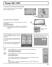
... standby mode. Power Indicator: Green Example: The screen below is displayed for a while after the Plasma Display is turned on. (setting condition is an example.) TH-42PWD8 INPUT MENU -/ VOL +/ ENTER/ TH-42PWD8 Power Indicator Remote Control Sensor When the POWER is turned on : Power-On. Power Indicator: Green Turn the power to turn the Plasma Display off. Fix the AC cord plug securely to the Plasma Display with the clamper. (see page 18) Select the desired language using the or button...
... standby mode. Power Indicator: Green Example: The screen below is displayed for a while after the Plasma Display is turned on. (setting condition is an example.) TH-42PWD8 INPUT MENU -/ VOL +/ ENTER/ TH-42PWD8 Power Indicator Remote Control Sensor When the POWER is turned on : Power-On. Power Indicator: Green Turn the power to turn the Plasma Display off. Fix the AC cord plug securely to the Plasma Display with the clamper. (see page 18) Select the desired language using the or button...

Plasma Display
Page 14
... page 21) SURROUND ON 14 Basic Controls Remote control sensor TH-42PWD8 INPUT MENU -/ VOL +/ ENTER/ Volume Adjustment Volume Up "+" Down "-" When the menu screen is still inserted into the wall outlet.) • Standby ......... Indicator not illuminated (The unit will light. • Power-OFF .... ON OFF MENU Screen ON / OFF Each time the MENU button is pressed. just as the power cord is displayed: "+": press to move the cursor up "-": press to...
... page 21) SURROUND ON 14 Basic Controls Remote control sensor TH-42PWD8 INPUT MENU -/ VOL +/ ENTER/ Volume Adjustment Volume Up "+" Down "-" When the menu screen is still inserted into the wall outlet.) • Standby ......... Indicator not illuminated (The unit will light. • Power-OFF .... ON OFF MENU Screen ON / OFF Each time the MENU button is pressed. just as the power cord is displayed: "+": press to move the cursor up "-": press to...

Plasma Display
Page 15
... part of the displayed image. 15 POSITION buttons R button (see page 17) Press the R button to return to select the INPUT mode. SET UP button (see page 13). Note: After-image (image lag) may occur on at the power switch (see page 16, 17) DIRECT INPUT buttons Press the INPUT "1", "2", "3" or "PC" input mode selection button to previous menu screen. Channel Adjustment This button cannot be plugged into the wall outlet and turned on the plasma display panel when a still picture is used...
... part of the displayed image. 15 POSITION buttons R button (see page 17) Press the R button to return to select the INPUT mode. SET UP button (see page 13). Note: After-image (image lag) may occur on at the power switch (see page 16, 17) DIRECT INPUT buttons Press the INPUT "1", "2", "3" or "PC" input mode selection button to previous menu screen. Channel Adjustment This button cannot be plugged into the wall outlet and turned on the plasma display panel when a still picture is used...

Plasma Display
Page 17
... OFF VIDEO NR OFF SYNC 3 : 2 PULLDOWN VIDEO NR H-FREQ. 33.8 V-FREQ. 60.0 AUTO OFF OFF kHz Hz 3 : 2 PULLDOWN VIDEO NR H-FREQ. 33.8 V-FREQ. 60.0 OFF OFF kHz Hz Note: "SIGNAL" setup menu displays a different setting condition for each adjust screen. [ from the unit ] INPUT MENU -/ VOL +/ ENTER/ Press to return to next menu screen. Press to set up POWER ON TIME / POWER OFF TIME. Press to previous menu. SET UP TIMER PRESENT TIME OF DAY...
... OFF VIDEO NR OFF SYNC 3 : 2 PULLDOWN VIDEO NR H-FREQ. 33.8 V-FREQ. 60.0 AUTO OFF OFF kHz Hz 3 : 2 PULLDOWN VIDEO NR H-FREQ. 33.8 V-FREQ. 60.0 OFF OFF kHz Hz Note: "SIGNAL" setup menu displays a different setting condition for each adjust screen. [ from the unit ] INPUT MENU -/ VOL +/ ENTER/ Press to return to next menu screen. Press to set up POWER ON TIME / POWER OFF TIME. Press to previous menu. SET UP TIMER PRESENT TIME OF DAY...

Plasma Display
Page 18
... the input signal Select the input signals to be selected for the main picture and sub picture. Press to select your preferred language. Press to select the input signal to be played back from the source connected to the component/RGB input terminals. (see page 36) • In 2 screen display, the same input mode cannot be connected by pressing the INPUT button on the unit. • Input terminal will change as...
... the input signal Select the input signals to be selected for the main picture and sub picture. Press to select your preferred language. Press to select the input signal to be played back from the source connected to the component/RGB input terminals. (see page 36) • In 2 screen display, the same input mode cannot be connected by pressing the INPUT button on the unit. • Input terminal will change as...
Plasma Display
Page 19
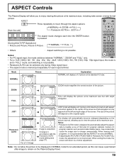
Notes: • Panasonic AUTO mode is not possible. When exiting the mode, the screen will return to handle a mix of 16:9 and 4:3 program material. ASPECT Controls The Plasma Display will allow the picture to be displayed in NORMAL mode for each time the ENTER button is pressed. [During MULTI PIP Operations] • Picture and Picture, Picture in accordance with slight elongation. 9 JUST 4 3 16 JUST mode will automatically become enlarged (depending...
Notes: • Panasonic AUTO mode is not possible. When exiting the mode, the screen will return to handle a mix of 16:9 and 4:3 program material. ASPECT Controls The Plasma Display will allow the picture to be displayed in NORMAL mode for each time the ENTER button is pressed. [During MULTI PIP Operations] • Picture and Picture, Picture in accordance with slight elongation. 9 JUST 4 3 16 JUST mode will automatically become enlarged (depending...
Plasma Display
Page 32
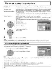
... turned ON, luminous level of the Plasma Display is suppressed, so power consumption is no signal. The unit power supply is turned ON or OFF depending on each Optional Terminal Board. INPUT LABEL POWER SAVE STANDBY SAVE POWER MANAGEMENT AUTO POWER OFF OSD LANGUAGE RGB PC OFF OFF OFF OFF ENGLISH (US) Note: While selecting a Input signal through Optional Terminal Board connected to change the label of the Input signal to On, the power supply...
... turned ON, luminous level of the Plasma Display is suppressed, so power consumption is no signal. The unit power supply is turned ON or OFF depending on each Optional Terminal Board. INPUT LABEL POWER SAVE STANDBY SAVE POWER MANAGEMENT AUTO POWER OFF OSD LANGUAGE RGB PC OFF OFF OFF OFF ENGLISH (US) Note: While selecting a Input signal through Optional Terminal Board connected to change the label of the Input signal to On, the power supply...
Plasma Display
Page 36
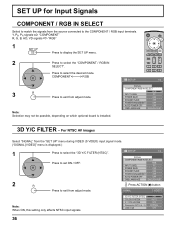
...) COLOR SYSTEM 3 : 2 PULLDOWN Panasonic AUTO (4 : 3) VIDEO NR ON AUTO OFF NORMAL OFF 36 SET UP for Input Signals COMPONENT / RGB IN SELECT Select to match the signals from adjust mode. For NTSC AV images Select "SIGNAL" from adjust mode. SIGNAL COMPONENT/RGB-IN SELECT Press to select the "COMPONENT / RGB-IN SELECT". Press to exit from the "SET UP" menu during VIDEO (S VIDEO) input signal mode. ("SIGNAL [VIDEO]" menu is installed. RGB INPUT LABEL PC POWER SAVE OFF STANDBY SAVE...
...) COLOR SYSTEM 3 : 2 PULLDOWN Panasonic AUTO (4 : 3) VIDEO NR ON AUTO OFF NORMAL OFF 36 SET UP for Input Signals COMPONENT / RGB IN SELECT Select to match the signals from adjust mode. For NTSC AV images Select "SIGNAL" from adjust mode. SIGNAL COMPONENT/RGB-IN SELECT Press to select the "COMPONENT / RGB-IN SELECT". Press to exit from the "SET UP" menu during VIDEO (S VIDEO) input signal mode. ("SIGNAL [VIDEO]" menu is installed. RGB INPUT LABEL PC POWER SAVE OFF STANDBY SAVE...

Plasma Display
Page 41
...", Pos. /Size adjustment cannot be used in "Remote ID" or "Serial ID". On Sets Advanced PIP mode (see page 21). Off Sets the normal image display size on . • This mode is available for DVI, SDI, HDMI's corresponding signals. Notes: • This functions when display is turned on screen. On Enable ID remote control functions. The "SHIPPING" menu is displayed and the lock is "On", you set to the "Button lock", "Remocon User level" or "Remote ID" adjustments, set all the...
...", Pos. /Size adjustment cannot be used in "Remote ID" or "Serial ID". On Sets Advanced PIP mode (see page 21). Off Sets the normal image display size on . • This mode is available for DVI, SDI, HDMI's corresponding signals. Notes: • This functions when display is turned on screen. On Enable ID remote control functions. The "SHIPPING" menu is displayed and the lock is "On", you set to the "Button lock", "Remocon User level" or "Remote ID" adjustments, set all the...

Plasma Display
Page 43
... on the remote control.) Not plugged into AC outlet Not switched on PICTURE and BRIGHTNESS/Volume setting (Check by pressing the power switch or stand-by rotation of input signal. Some parts of time. The display unit is not designed to display fixed images for the picture to appear when the power has been turned on the Plasma Display. Note: The permanent after -image to flicker in the 16:9 mode, blank areas...
... on the remote control.) Not plugged into AC outlet Not switched on PICTURE and BRIGHTNESS/Volume setting (Check by pressing the power switch or stand-by rotation of input signal. Some parts of time. The display unit is not designed to display fixed images for the picture to appear when the power has been turned on the Plasma Display. Note: The permanent after -image to flicker in the 16:9 mode, blank areas...

Plasma Display
Page 45
... Y : 1.0 Vp-p (75-ohm : include sync) PB/CB : ± 0.7 Vp-p (75-ohm) PR/CR : ± 0.7 Vp-p (75-ohm) HD, VD/1.0 - 5.0 Vp-p (high impedance) AUDIO IN (M3 JACK) 0.5 Vrms (high impedance) SERIAL EXTERNAL CONTROL TERMINAL (D-SUB 9PIN) RS-232C COMPATIBLE SPEAKERS (6 ȍ) Accessories Supplied 16W [8 W + 8 W] (10 % THD) Remote Control Transmitter EUR7636070R Batteries 2 × AA Size Fixing bands (TMME203 or TMME187) × 2 Dimensions (W × H × D) 36...
... Y : 1.0 Vp-p (75-ohm : include sync) PB/CB : ± 0.7 Vp-p (75-ohm) PR/CR : ± 0.7 Vp-p (75-ohm) HD, VD/1.0 - 5.0 Vp-p (high impedance) AUDIO IN (M3 JACK) 0.5 Vrms (high impedance) SERIAL EXTERNAL CONTROL TERMINAL (D-SUB 9PIN) RS-232C COMPATIBLE SPEAKERS (6 ȍ) Accessories Supplied 16W [8 W + 8 W] (10 % THD) Remote Control Transmitter EUR7636070R Batteries 2 × AA Size Fixing bands (TMME203 or TMME187) × 2 Dimensions (W × H × D) 36...

Plasma Display
Page 46
... Y : 1.0 Vp-p (75-ohm : include sync) PB/CB : ± 0.7 Vp-p (75-ohm) PR/CR : ± 0.7 Vp-p (75-ohm) HD, VD/1.0 - 5.0 Vp-p (high impedance) AUDIO IN (M3 JACK) 0.5 Vrms (high impedance) SERIAL EXTERNAL CONTROL TERMINAL (D-SUB 9PIN) RS-232C COMPATIBLE SPEAKERS (6 ȍ) 16W [8 W + 8 W] (10 % THD) Accessories Supplied Remote Control Transmitter EUR7636070R Batteries 2 × AA Size Fixing bands (TMME203 or TMME187) × 2 Dimensions (W × H × D) 36...
... Y : 1.0 Vp-p (75-ohm : include sync) PB/CB : ± 0.7 Vp-p (75-ohm) PR/CR : ± 0.7 Vp-p (75-ohm) HD, VD/1.0 - 5.0 Vp-p (high impedance) AUDIO IN (M3 JACK) 0.5 Vrms (high impedance) SERIAL EXTERNAL CONTROL TERMINAL (D-SUB 9PIN) RS-232C COMPATIBLE SPEAKERS (6 ȍ) 16W [8 W + 8 W] (10 % THD) Accessories Supplied Remote Control Transmitter EUR7636070R Batteries 2 × AA Size Fixing bands (TMME203 or TMME187) × 2 Dimensions (W × H × D) 36...
Plasma Display
Page 47
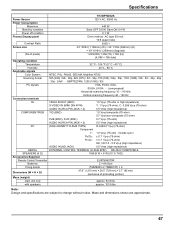
Mass and dimensions shown are subject to change without notice. Specifications Power Source Power Consumption Maximum Stand-by condition Power off condition Plasma Display panel Contrast Ratio Screen size (No.of pixels) Operating condition Temperature Humidity Applicable signals Color System Scanning format PC signals Connection terminals AV COMPONENT/RGB PC SERIAL SPEAKERS (6 ȍ) Accessories Supplied Remote Control Transmitter Batteries Fixing bands Dimensions (W × H × D) Mass (weight) main unit only with speakers TH-50PHD8UK 120 V AC, 50/60...
Mass and dimensions shown are subject to change without notice. Specifications Power Source Power Consumption Maximum Stand-by condition Power off condition Plasma Display panel Contrast Ratio Screen size (No.of pixels) Operating condition Temperature Humidity Applicable signals Color System Scanning format PC signals Connection terminals AV COMPONENT/RGB PC SERIAL SPEAKERS (6 ȍ) Accessories Supplied Remote Control Transmitter Batteries Fixing bands Dimensions (W × H × D) Mass (weight) main unit only with speakers TH-50PHD8UK 120 V AC, 50/60...


