
Operating Instructions
Page 4
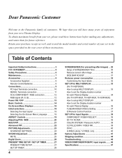
... Digital Zoom 26 PRESENT TIME SETUP / SET UP TIMER 27 PRESENT TIME SETUP 27 SET UP TIMER 28 4 SCREENSAVER (For preventing after-images) ... 29 Setup of SCREENSAVER Time 30 Reduces screen after-image 30 SIDE BAR ADJUST 31 Reduces power consumption 32 Customizing the Input labels 32 SET UP for MULTI DISPLAY 33 (For TH-42PS9UK) How to setup MULTI DISPLAY 33 How to set the Display location number for each Plasma Display 36 F (SEAM HIDES VIDEO) Setting 37 ID Remote Control...
... Digital Zoom 26 PRESENT TIME SETUP / SET UP TIMER 27 PRESENT TIME SETUP 27 SET UP TIMER 28 4 SCREENSAVER (For preventing after-images) ... 29 Setup of SCREENSAVER Time 30 Reduces screen after-image 30 SIDE BAR ADJUST 31 Reduces power consumption 32 Customizing the Input labels 32 SET UP for MULTI DISPLAY 33 (For TH-42PS9UK) How to setup MULTI DISPLAY 33 How to set the Display location number for each Plasma Display 36 F (SEAM HIDES VIDEO) Setting 37 ID Remote Control...
Operating Instructions
Page 5
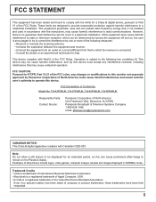
...: Do not allow a still picture to be determined by turning the equipment off and on, the user is a registered trademark of the FCC Rules. These limits are designed to provide reasonable protection against harmful interference in NORMAL mode. FCC Declaration of still pictures include logos, video games, computer images, teletext and images displayed in a residential installation. Trademark Credits • VGA is...
...: Do not allow a still picture to be determined by turning the equipment off and on, the user is a registered trademark of the FCC Rules. These limits are designed to provide reasonable protection against harmful interference in NORMAL mode. FCC Declaration of still pictures include logos, video games, computer images, teletext and images displayed in a residential installation. Trademark Credits • VGA is...
Operating Instructions
Page 6
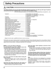
... possibility of injury. (All of the following optional accessories. When using the Plasma Display Do not bring your infrared sensor in turn, can present choking hazard if accidentally swallowed. Small parts can cause fire or electric shock. Install your hands, face or objects close . Disconnect the power plug from being released through the ventilation holes. Discard unneeded small...
... possibility of injury. (All of the following optional accessories. When using the Plasma Display Do not bring your infrared sensor in turn, can present choking hazard if accidentally swallowed. Small parts can cause fire or electric shock. Install your hands, face or objects close . Disconnect the power plug from being released through the ventilation holes. Discard unneeded small...
Operating Instructions
Page 7
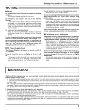
...the Display under these conditions might damage the power cable. If problems occur during use of the Plasma Display. Have the Display evaluated at the rear. Contact an Authorized Service Center for a long period of the surface may be made from the wall outlet. Furthermore, do anything that need to come into ... time, unplug the power cord from rubber or PVC. 7 Securely insert the power cord plug as far as no picture or no sound), or if smoke or an abnormal odor is designed to which could cause fire. Do not handle the power cord plug with a soft, lint-free ...
...the Display under these conditions might damage the power cable. If problems occur during use of the Plasma Display. Have the Display evaluated at the rear. Contact an Authorized Service Center for a long period of the surface may be made from the wall outlet. Furthermore, do anything that need to come into ... time, unplug the power cord from rubber or PVC. 7 Securely insert the power cord plug as far as no picture or no sound), or if smoke or an abnormal odor is designed to which could cause fire. Do not handle the power cord plug with a soft, lint-free ...
Operating Instructions
Page 10
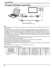
... not be input are DDC1/2B-compatible. If the display resolution exceeds these maximums, it may have trouble connecting Mini D-sub 15P cable with a horizontal scanning frequency of 15 to 110 kHz and vertical scanning frequency of 48 to 120 Hz. (However, the image will need to make setting changes to the computer at the time of connection. • Some PC models cannot be connected to the set. •...
... not be input are DDC1/2B-compatible. If the display resolution exceeds these maximums, it may have trouble connecting Mini D-sub 15P cable with a horizontal scanning frequency of 15 to 110 kHz and vertical scanning frequency of 48 to 120 Hz. (However, the image will need to make setting changes to the computer at the time of connection. • Some PC models cannot be connected to the set. •...
Operating Instructions
Page 11
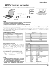
... multiple commands are not supplied with a STX signal, followed by the command, the parameters, and lastly an ETX signal in that the Plasma Display can be controlled by a computer which satisfies the conditions given below. SERIAL Terminals connection The SERIAL terminal is used when the Plasma Display is controlled by mistake, this set. COMPUTER RS-232C Straight cable SERIAL Connections 6789 12345 Pin layout for...
... multiple commands are not supplied with a STX signal, followed by the command, the parameters, and lastly an ETX signal in that the Plasma Display can be controlled by a computer which satisfies the conditions given below. SERIAL Terminals connection The SERIAL terminal is used when the Plasma Display is controlled by mistake, this set. COMPUTER RS-232C Straight cable SERIAL Connections 6789 12345 Pin layout for...
Operating Instructions
Page 13
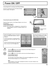
... done from the setup menu. (see page 9) Connecting the plug to the Wall Outlet Press the Power switch on the Plasma Display to turn the set on the remote control to turn the Plasma Display on for a while after the Plasma Display is turned on. (setting condition is an example.) TH-42PWD8 INPUT MENU -/ VOL +/ ENTER/ TH-42PS9 Power Indicator Remote Control Sensor When the POWER is displayed. Power Indicator: Red (standby) Press the button on the remote control to the Plasma Display off by...
... done from the setup menu. (see page 9) Connecting the plug to the Wall Outlet Press the Power switch on the Plasma Display to turn the set on the remote control to turn the Plasma Display on for a while after the Plasma Display is turned on. (setting condition is an example.) TH-42PWD8 INPUT MENU -/ VOL +/ ENTER/ TH-42PS9 Power Indicator Remote Control Sensor When the POWER is displayed. Power Indicator: Red (standby) Press the button on the remote control to the Plasma Display off by...
Operating Instructions
Page 14
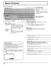
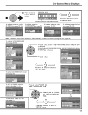
... wall outlet.) • Standby ......... Note: The surround settings are enormous. Indicator not illuminated (The unit will light. • Power-OFF .... ON OFF MENU Screen ON / OFF Each time the MENU button is pressed. Green • DPMS Orange (With PC input signal and during operation of surround sound are memorized separately for each time the SURROUND button is pressed, the menu screen will switch. (see page 16) Normal Viewing PICTURE SET UP SOUND POS. /SIZE INPUT button...
... wall outlet.) • Standby ......... Note: The surround settings are enormous. Indicator not illuminated (The unit will light. • Power-OFF .... ON OFF MENU Screen ON / OFF Each time the MENU button is pressed. Green • DPMS Orange (With PC input signal and during operation of surround sound are memorized separately for each time the SURROUND button is pressed, the menu screen will switch. (see page 16) Normal Viewing PICTURE SET UP SOUND POS. /SIZE INPUT button...
Operating Instructions
Page 15
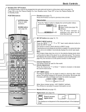
... turn the Plasma Display On, from Standby mode. Volume Adjustment Press the Volume Up "+" or Down "-" button to Standby mode. This displays an enlargement of the designated part of the displayed image. 15 If you press the button whose slot is kept on the plasma display panel when a still picture is not installed, it automatically displays the current input signal. Basic Controls Standby (ON / OFF) button The Plasma Display must first be used to switch directly to after-image. Note: After-image (image...
... turn the Plasma Display On, from Standby mode. Volume Adjustment Press the Volume Up "+" or Down "-" button to Standby mode. This displays an enlargement of the designated part of the displayed image. 15 If you press the button whose slot is kept on the plasma display panel when a still picture is not installed, it automatically displays the current input signal. Basic Controls Standby (ON / OFF) button The Plasma Display must first be used to switch directly to after-image. Note: After-image (image...
Operating Instructions
Page 17
...) SIGNAL [ Digital ] 3D Y/C FILTER (NTSC) COLOR SYSTEM 3 : 2 PULLDOWN Panasonic AUTO (4 : 3) VIDEO NR ON AUTO OFF NORMAL OFF 3 : 2 PULLDOWN OFF VIDEO NR OFF SYNC 3 : 2 PULLDOWN VIDEO NR H-FREQ. 33.8 V-FREQ. 60.0 AUTO OFF OFF kHz Hz 3 : 2 PULLDOWN VIDEO NR H-FREQ. 33.8 V-FREQ. 60.0 OFF OFF kHz Hz Note: "SIGNAL" setup menu displays a different setting condition for each adjust screen. [ from the unit ] INPUT MENU -/ VOL +/ ENTER/ Press to return to select POWER ON TIME / POWER...
...) SIGNAL [ Digital ] 3D Y/C FILTER (NTSC) COLOR SYSTEM 3 : 2 PULLDOWN Panasonic AUTO (4 : 3) VIDEO NR ON AUTO OFF NORMAL OFF 3 : 2 PULLDOWN OFF VIDEO NR OFF SYNC 3 : 2 PULLDOWN VIDEO NR H-FREQ. 33.8 V-FREQ. 60.0 AUTO OFF OFF kHz Hz 3 : 2 PULLDOWN VIDEO NR H-FREQ. 33.8 V-FREQ. 60.0 OFF OFF kHz Hz Note: "SIGNAL" setup menu displays a different setting condition for each adjust screen. [ from the unit ] INPUT MENU -/ VOL +/ ENTER/ Press to return to select POWER ON TIME / POWER...
Operating Instructions
Page 18
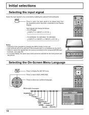
... STANDBY SAVE OFF POWER MANAGEMENT OFF AUTO POWER OFF OSD LANGUAGE OFF ENGLISH (US) 18 Press to select your preferred language. Input signals will not be selected if the terminal board is not installed into the SLOT. • Select to match the signals from the source connected to the component/RGB input terminals. (see page 38) • In 2 screen display, the same input mode cannot be played...
... STANDBY SAVE OFF POWER MANAGEMENT OFF AUTO POWER OFF OSD LANGUAGE OFF ENGLISH (US) 18 Press to select your preferred language. Input signals will not be selected if the terminal board is not installed into the SLOT. • Select to match the signals from the source connected to the component/RGB input terminals. (see page 38) • In 2 screen display, the same input mode cannot be played...
Operating Instructions
Page 19
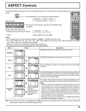
... screen will return to a former adjustment. • Panasonic AUTO can not be selected only during Video signal input. • The aspect mode is memorized separately for an extended period, as stock market data screens, may occasionally cause the image size to change unexpectedly. The display will automatically become enlarged (depending on the Plasma Display Panel. 19 ASPECT Controls The Plasma Display will allow the picture to be set to "FULL" mode, and switching...
... screen will return to a former adjustment. • Panasonic AUTO can not be selected only during Video signal input. • The aspect mode is memorized separately for an extended period, as stock market data screens, may occasionally cause the image size to change unexpectedly. The display will automatically become enlarged (depending on the Plasma Display Panel. 19 ASPECT Controls The Plasma Display will allow the picture to be set to "FULL" mode, and switching...
Operating Instructions
Page 20
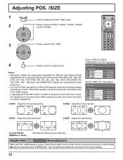
... in Panasonic AUTO with FULL mode, the adjustment is received, the picture position will return to the factory settings. 20 V-SIZE Adjust the vertical size. When exiting the mode, the screen will shift up or down. Adjusting POS. /SIZE 1 Press to display the POS. /SIZE menu. 2 Press to select H-POS / H-SIZE / V-POS / V-SIZE / CLOCK PHASE. 3 Press to adjust POS. /SIZE. 4 Press to exit from a VCR or DVD player is not memorized. H-SIZE Adjust the horizontal size. Notes: • Adjustment...
... in Panasonic AUTO with FULL mode, the adjustment is received, the picture position will return to the factory settings. 20 V-SIZE Adjust the vertical size. When exiting the mode, the screen will shift up or down. Adjusting POS. /SIZE 1 Press to display the POS. /SIZE menu. 2 Press to select H-POS / H-SIZE / V-POS / V-SIZE / CLOCK PHASE. 3 Press to adjust POS. /SIZE. 4 Press to exit from a VCR or DVD player is not memorized. H-SIZE Adjust the horizontal size. Notes: • Adjustment...

Operating Instructions
Page 25
... sound. DYNAMIC Accentuates sharp sound. MAIN SUB Selects Main picture sound. Selects PIP frame sound. Helpful Hint ( / NORMALIZE Normalization) While the "SOUND" menu is displayed, if either the N button on the remote control is pressed at any time or the ACTION ( ) button is displayed on right side of the audio output screen label. MUTE Useful when answering the phone or receiving unexpected visitors. Notes: • Press the SURROUND button to directly turn...
... sound. DYNAMIC Accentuates sharp sound. MAIN SUB Selects Main picture sound. Selects PIP frame sound. Helpful Hint ( / NORMALIZE Normalization) While the "SOUND" menu is displayed, if either the N button on the remote control is pressed at any time or the ACTION ( ) button is displayed on right side of the audio output screen label. MUTE Useful when answering the phone or receiving unexpected visitors. Notes: • Press the SURROUND button to directly turn...
Operating Instructions
Page 32
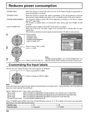
... Terminal Board connected to exit from PC (Mini D-sub) terminal. This function is enabled when it is turned ON. (Only during power supply standby (see below). Press to change the label of the Input signal to select "POWER SAVE" "STANDBY SAVE" "POWER MANAGEMENT" "AUTO POWER OFF". SET UP 1/2 SIGNAL COMPONENT/RGB-IN SELECT Press to select "ON" or "OFF". When this is a signal during normal viewing (one picture screen) only...
... Terminal Board connected to exit from PC (Mini D-sub) terminal. This function is enabled when it is turned ON. (Only during power supply standby (see below). Press to change the label of the Input signal to select "POWER SAVE" "STANDBY SAVE" "POWER MANAGEMENT" "AUTO POWER OFF". SET UP 1/2 SIGNAL COMPONENT/RGB-IN SELECT Press to select "ON" or "OFF". When this is a signal during normal viewing (one picture screen) only...
Operating Instructions
Page 38
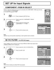
... adjust mode. Y, PB, PR signals "COMPONENT" R, G, B, HD, VD signals "RGB" 1 Press to display the SET UP menu. 2 Press to select the desired mode. Press to select the "COMPONENT / RGB-IN SELECT". SIGNAL [ VIDEO ] Note: When ON, this setting only affects NTSC input signals. 3D Y/C FILTER (NTSC) COLOR SYSTEM 3 : 2 PULLDOWN Panasonic AUTO (4 : 3) VIDEO NR ON AUTO OFF NORMAL OFF 38 For NTSC AV images Select "SIGNAL" from the "SET UP" menu during VIDEO (S VIDEO) input signal mode. ("SIGNAL [VIDEO]" menu is installed...
... adjust mode. Y, PB, PR signals "COMPONENT" R, G, B, HD, VD signals "RGB" 1 Press to display the SET UP menu. 2 Press to select the desired mode. Press to select the "COMPONENT / RGB-IN SELECT". SIGNAL [ VIDEO ] Note: When ON, this setting only affects NTSC input signals. 3D Y/C FILTER (NTSC) COLOR SYSTEM 3 : 2 PULLDOWN Panasonic AUTO (4 : 3) VIDEO NR ON AUTO OFF NORMAL OFF 38 For NTSC AV images Select "SIGNAL" from the "SET UP" menu during VIDEO (S VIDEO) input signal mode. ("SIGNAL [VIDEO]" menu is installed...
Operating Instructions
Page 42
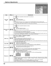
... Terminal board is installed. • Input switch can be fixed as the value input in the single screen display mode. On: Sets the image display size approximately 95 % of your volume setting before opening the options menu if you cannot use all the settings adjusted. Press button to 63 regardless of the settings. • You can hear the changed volume regardless of the normal image display. Off: Sets normal two screen display mode (see page 22). Advanced PIP...
... Terminal board is installed. • Input switch can be fixed as the value input in the single screen display mode. On: Sets the image display size approximately 95 % of your volume setting before opening the options menu if you cannot use all the settings adjusted. Press button to 63 regardless of the settings. • You can hear the changed volume regardless of the normal image display. Off: Sets normal two screen display mode (see page 22). Advanced PIP...
Operating Instructions
Page 43
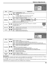
... used . MENU ENTER/ On: Locks all the buttons on the remote control. Sets panel ID number when panel is released when it disappears. 43 Sets the panel ID Control. Off On Off: Disables external control by the ID. buttons on remote control. Off On On: Enable ID remote control functions. Off User1 User2 User3 Off: You can use all the buttons are disabled due to the "Button lock", "Remocon User level" or "Remote ID" adjustments, set Display vertically. You can use...
... used . MENU ENTER/ On: Locks all the buttons on the remote control. Sets panel ID number when panel is released when it disappears. 43 Sets the panel ID Control. Off On Off: Disables external control by the ID. buttons on remote control. Off On On: Enable ID remote control functions. Off User1 User2 User3 Off: You can use all the buttons are disabled due to the "Button lock", "Remocon User level" or "Remote ID" adjustments, set Display vertically. You can use...
Operating Instructions
Page 45
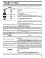
... top and bottom of the screen. This Plasma Display uses special image processing. The brightness on the remote control.) If a signal with minimal movements are shown. Plasma Display panel Symptoms Check The screen darkens slightly when bright pictures with a non-applicable color system format, or frequency is input, only the input terminal indication is not covered by any other aspects. whirring sound is caused by button on both sides mode changes.
... top and bottom of the screen. This Plasma Display uses special image processing. The brightness on the remote control.) If a signal with minimal movements are shown. Plasma Display panel Symptoms Check The screen darkens slightly when bright pictures with a non-applicable color system format, or frequency is input, only the input terminal indication is not covered by any other aspects. whirring sound is caused by button on both sides mode changes.
Operating Instructions
Page 51
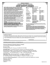
... Abington Way, Houston, TX 77008 (713) 802-2726 No. PCI agrees to the latter location requires a return authorization before shipment. Repaired or replacement parts supplied during the applicable warranty coverage period described below . Model Number Serial Number ¤ 2006 Matsushita Electric Industrial Co., Ltd. The owner must be found on video display products are not defects and are not covered under normal...
... Abington Way, Houston, TX 77008 (713) 802-2726 No. PCI agrees to the latter location requires a return authorization before shipment. Repaired or replacement parts supplied during the applicable warranty coverage period described below . Model Number Serial Number ¤ 2006 Matsushita Electric Industrial Co., Ltd. The owner must be found on video display products are not defects and are not covered under normal...


