Operating Instructions
Page 1
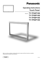
TY-TP42P10S TY-TP50P10S TY-TP58P10S TY-TP65P10S Before connecting, operating or adjusting this manual for future reference. English TQZH939-5 Please keep this product, please read these instructions completely. Operating Instructions Touch Panel Model No.
TY-TP42P10S TY-TP50P10S TY-TP58P10S TY-TP65P10S Before connecting, operating or adjusting this manual for future reference. English TQZH939-5 Please keep this product, please read these instructions completely. Operating Instructions Touch Panel Model No.
Operating Instructions
Page 2
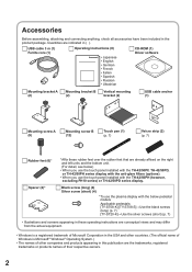
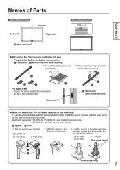
... screw (short) (4) *To use the touch panel installed with the TH-42/50PH (however, excluding PH10 series) or TH-42/50PD series display. USB cable 3 m (1) Ferrite core (1) Operating Instructions (8) • Japanese • English • German • French • Italian • Spanish • Russian • Ukrainian CD-ROM (1) Driver software Mounting bracket A (2) Mounting bracket B (2) Vertical mounting bracket (2) USB cable anchor (1) Mounting screw A (9) Mounting screw B (12) Touch pen (1) (p. 7) Velcro strip...
... screw (short) (4) *To use the touch panel installed with the TH-42/50PH (however, excluding PH10 series) or TH-42/50PD series display. USB cable 3 m (1) Ferrite core (1) Operating Instructions (8) • Japanese • English • German • French • Italian • Spanish • Russian • Ukrainian CD-ROM (1) Driver software Mounting bracket A (2) Mounting bracket B (2) Vertical mounting bracket (2) USB cable anchor (1) Mounting screw A (9) Mounting screw B (12) Touch pen (1) (p. 7) Velcro strip...
Operating Instructions
Page 3
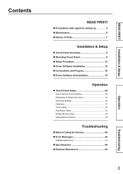
... Parts 7 Installation & Setup ■ Touch Panel Assembly 8 ■ Mounting Touch Panel 9 ■ Setup Procedure 13 ■ Driver Software Installation 14 ■ Connections and Plug-Ins 16 ■ Driver Software Uninstallation 19 Operation ■ Touch Panel Setup 20 How to Use the Driver Software 20 Explanation of Setup Panel Items 21 Advanced Settings 25 Calibration 27 Touch setting 29 Area Button Setup 32 Multiple Monitor Setup 35 Setting Sensor Position 39 Troubleshooting ■ Before Calling for Service 40 ■ Error Messages 42 USB Bandwidth Error...
... Parts 7 Installation & Setup ■ Touch Panel Assembly 8 ■ Mounting Touch Panel 9 ■ Setup Procedure 13 ■ Driver Software Installation 14 ■ Connections and Plug-Ins 16 ■ Driver Software Uninstallation 19 Operation ■ Touch Panel Setup 20 How to Use the Driver Software 20 Explanation of Setup Panel Items 21 Advanced Settings 25 Calibration 27 Touch setting 29 Area Button Setup 32 Multiple Monitor Setup 35 Setting Sensor Position 39 Troubleshooting ■ Before Calling for Service 40 ■ Error Messages 42 USB Bandwidth Error...

Operating Instructions
Page 4
... the touch panel unit to the plasma display. • The weight of the equipment and cause injury. To prevent incorrect operation, do not use other than those given in an extremely hot or cold location may damage the cord, and cause a fire or electric shock. CAUTION When unplugging the USB cable, be sure to grip the connector. •...
... the touch panel unit to the plasma display. • The weight of the equipment and cause injury. To prevent incorrect operation, do not use other than those given in an extremely hot or cold location may damage the cord, and cause a fire or electric shock. CAUTION When unplugging the USB cable, be sure to grip the connector. •...
Operating Instructions
Page 5
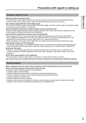
... infrared rays and may cause incorrect operation or malfunction. Use only the touch pen included with a power supply exceeding the rating may operate incorrectly if the infrared transmissive part becomes soiled. Use a soft dry cloth to the rated voltage. Keep foreign matter out of the equipment. Setup location Before setting up Cautions when in use near emissions of electrical noise (generators...
... infrared rays and may cause incorrect operation or malfunction. Use only the touch pen included with a power supply exceeding the rating may operate incorrectly if the infrared transmissive part becomes soiled. Use a soft dry cloth to the rated voltage. Keep foreign matter out of the equipment. Setup location Before setting up Cautions when in use near emissions of electrical noise (generators...
Operating Instructions
Page 7
... pedestal To use the plasma display with the below pedestal models, install the spacer included with the touch panel on the pole of the arrow. Lock the spacer to the pole using the included screws that are suitable for the applicable pedestal. [TY-ST08-K] [TY-ST08-S] [TY-ST20-K] Silver screw (short) Black screw (long...
... pedestal To use the plasma display with the below pedestal models, install the spacer included with the touch panel on the pole of the arrow. Lock the spacer to the pole using the included screws that are suitable for the applicable pedestal. [TY-ST08-K] [TY-ST08-S] [TY-ST20-K] Silver screw (short) Black screw (long...
Operating Instructions
Page 11
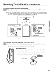
... attach the touch panel to the plasma display. Mounting Touch Panel (in Vertical Posture) 1 Attach mounting brackets to the touch panel. Fit the protrusions on the vertical mounting brackets into the holes of the unit and affix the brackets with the top and bottom edges of the plasma display. Service for damage caused by installation in the diagrams, tighten mounting screws...
... attach the touch panel to the plasma display. Mounting Touch Panel (in Vertical Posture) 1 Attach mounting brackets to the touch panel. Fit the protrusions on the vertical mounting brackets into the holes of the unit and affix the brackets with the top and bottom edges of the plasma display. Service for damage caused by installation in the diagrams, tighten mounting screws...
Operating Instructions
Page 13
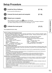
... error message is displayed, see "Before Calling for Service" (p. 40) and "Error Messages". (p. 42) 44 Calibrate the touch panel This completes the basic setup. (P. 27) ■ Driver Software Operating Environment The Driver software is supported by touching the touch panel. • If your environment, a USB hub with power supply may be required regardless of the condition above .) • If using Windows Vista/7 and user account control, the touch panel does not respond to touch...
... error message is displayed, see "Before Calling for Service" (p. 40) and "Error Messages". (p. 42) 44 Calibrate the touch panel This completes the basic setup. (P. 27) ■ Driver Software Operating Environment The Driver software is supported by touching the touch panel. • If your environment, a USB hub with power supply may be required regardless of the condition above .) • If using Windows Vista/7 and user account control, the touch panel does not respond to touch...
Operating Instructions
Page 15
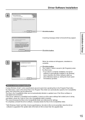
... the Compatibility folder from operating files in the Compatibility folder is newer than the upgrade data. 15 Click this button. For that reason, some specifications prevent users from where they can be referenced. The "LSaDrv" folder is saved in the Compatibility folder are referenced for settings. Driver Software Installation 4 Installation & Setup Click this button. The files in [All Programs] under the Start menu. •...
... the Compatibility folder from operating files in the Compatibility folder is newer than the upgrade data. 15 Click this button. For that reason, some specifications prevent users from where they can be referenced. The "LSaDrv" folder is saved in the Compatibility folder are referenced for settings. Driver Software Installation 4 Installation & Setup Click this button. The files in [All Programs] under the Start menu. •...
Operating Instructions
Page 16
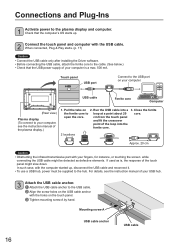
... instruction manual of your USB hub. 3 Attach the USB cable anchor. Attach the USB cable anchor to loop at a point about 20 open the core. When connected, Plug & Play starts. (p. 17) Caution • Connect the USB cable only after installing the Driver software. • Before connecting the USB cable, attach the ferrite core to the hub. Connections and Plug-Ins 1 Activate power to the USB port on your computer. If used as defective elements. Mounting...
... instruction manual of your USB hub. 3 Attach the USB cable anchor. Attach the USB cable anchor to loop at a point about 20 open the core. When connected, Plug & Play starts. (p. 17) Caution • Connect the USB cable only after installing the Driver software. • Before connecting the USB cable, attach the ferrite core to the hub. Connections and Plug-Ins 1 Activate power to the USB port on your computer. If used as defective elements. Mounting...
Operating Instructions
Page 20
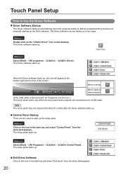
... driver" from the menu that appears. 20 When running When cable is disconnected (If the USB cable is explained the procedure for a while after the Driver software starts up. ■ Control Panel Startup There are connected over the icon.) The touch panel works only when the touch panel and computer are two ways to Use the Driver Software ■ Driver Software Startup The Driver software starts up automatically when the computer starts...
... driver" from the menu that appears. 20 When running When cable is disconnected (If the USB cable is explained the procedure for a while after the Driver software starts up. ■ Control Panel Startup There are connected over the icon.) The touch panel works only when the touch panel and computer are two ways to Use the Driver Software ■ Driver Software Startup The Driver software starts up automatically when the computer starts...
Operating Instructions
Page 22
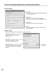
... Driver software was first installed. ■ Basic setting This tab is for making the basic settings for optimizing touch panel use. (p. 29) Click action: This is the best setting if often using clicking operations (i.e., web link clicks, etc.). checkbox to connect the touch panel with multiple monitors. Drag action: This is the best setting if often using dragging operations (i.e., drawing, electronic blackboards, etc.). User setting: Applies the setup...
... Driver software was first installed. ■ Basic setting This tab is for making the basic settings for optimizing touch panel use. (p. 29) Click action: This is the best setting if often using clicking operations (i.e., web link clicks, etc.). checkbox to connect the touch panel with multiple monitors. Drag action: This is the best setting if often using dragging operations (i.e., drawing, electronic blackboards, etc.). User setting: Applies the setup...
Operating Instructions
Page 25
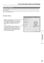
... default is applied. 25 Operation The "Touch panels to be set", "OK", "Cancel" and "Apply" buttons operate in this checkbox, an error message is not displayed even if an error occurs. Touch Panel Setup (Advanced Settings) Advanced Settings The "Advanced Settings" window appears when the "Advanced" button on the "Basic setting" tab of the setup panel is clicked on the touch panel as the common area buttons of two consecutive touches...
... default is applied. 25 Operation The "Touch panels to be set", "OK", "Cancel" and "Apply" buttons operate in this checkbox, an error message is not displayed even if an error occurs. Touch Panel Setup (Advanced Settings) Advanced Settings The "Advanced Settings" window appears when the "Advanced" button on the "Basic setting" tab of the setup panel is clicked on the touch panel as the common area buttons of two consecutive touches...
Operating Instructions
Page 28
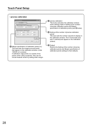
... picture when using a projector, they can be moved towards center by setting wider margin. precise calibration: This button activates the calibration window at the settings made in Setting of the number of precise calibration points and Margin specification of calibration points (see below). Setting of the number of precise calibration points: This area sets the number of calibration points settings to display in the calibration window. Touch Panel Setup...
... picture when using a projector, they can be moved towards center by setting wider margin. precise calibration: This button activates the calibration window at the settings made in Setting of the number of precise calibration points and Margin specification of calibration points (see below). Setting of the number of precise calibration points: This area sets the number of calibration points settings to display in the calibration window. Touch Panel Setup...
Operating Instructions
Page 30
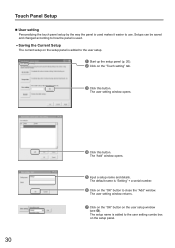
..." window opens. Input a setup name and details. The user setting window opens. 30 Click this button. Setups can be saved and changed according to how the panel is used makes it easier to use. The default name is added to the user setting combo box on the setup panel. The user setting window returns. Click on the "OK" button on the user setup window (see ). The setup name is "Setting" + a serial number...
..." window opens. Input a setup name and details. The user setting window opens. 30 Click this button. Setups can be saved and changed according to how the panel is used makes it easier to use. The default name is added to the user setting combo box on the setup panel. The user setting window returns. Click on the "OK" button on the user setup window (see ). The setup name is "Setting" + a serial number...
Operating Instructions
Page 31
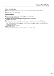
... the setup panel. 31 Changes are saved. The user setting window opens. Select the user setup to the current setup on the setup panel, click on the "OK" button. (The settings on the setup panel when the user setting window is started up the targeted setup on the setup panel and then edit the user setup.) The user setup window returns. Click on the "Edit" button. Touch Panel Setup • Calling Saved Setups Select a setup...
... the setup panel. 31 Changes are saved. The user setting window opens. Select the user setup to the current setup on the setup panel, click on the "OK" button. (The settings on the setup panel when the user setting window is started up the targeted setup on the setup panel and then edit the user setup.) The user setup window returns. Click on the "Edit" button. Touch Panel Setup • Calling Saved Setups Select a setup...
Operating Instructions
Page 35
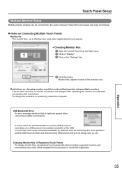
... such as connecting the touch panels to that are changed after disconnecting supported monitors and reconnecting new ones, either reregister the touch panel or cancel the registration. 35 Operation of the USB. appear in Windows are used when registering the touch panels. • Checking Monitor Nos. Open the Control Panel from the Start menu. Click on "Display". Click on Connecting Multiple Touch Panels Monitor...
... such as connecting the touch panels to that are changed after disconnecting supported monitors and reconnecting new ones, either reregister the touch panel or cancel the registration. 35 Operation of the USB. appear in Windows are used when registering the touch panels. • Checking Monitor Nos. Open the Control Panel from the Start menu. Click on "Display". Click on Connecting Multiple Touch Panels Monitor...
Operating Instructions
Page 40
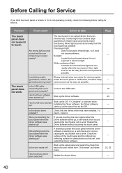
... not to work. Restart the Driver software without touching the touch panel. Check the surface of infrared rays can readily affect the touch panel. Are strong light sources or devices that the device driver has been installed. Incident light that contains large quantities of the touch panel and the infrared ray reflecting surface for service. Connect the USB cable. Check that use infrared rays...
... not to work. Restart the Driver software without touching the touch panel. Check the surface of infrared rays can readily affect the touch panel. Are strong light sources or devices that the device driver has been installed. Incident light that contains large quantities of the touch panel and the infrared ray reflecting surface for service. Connect the USB cable. Check that use infrared rays...
Operating Instructions
Page 41
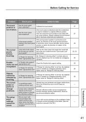
... operation. The setup panel settings cannot be recognized as a dragging operation. Has the touch panel been calibrated? If the wrong sensor position is out of place. Start up the setup panel and select the mode that the slightest touch is not treated as possible. Before Calling for Service Problem Check point Action to take Page The touch position is set for the touch panel, the direction...
... operation. The setup panel settings cannot be recognized as a dragging operation. Has the touch panel been calibrated? If the wrong sensor position is out of place. Start up the setup panel and select the mode that the slightest touch is not treated as possible. Before Calling for Service Problem Check point Action to take Page The touch position is set for the touch panel, the direction...
Operating Instructions
Page 44
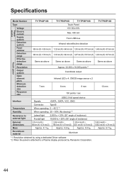
Specifications Model Number TY-TP42P10S TY-TP50P10S TY-TP58P10S TY-TP65P10S Type Touch Panel Power source Touch panel Voltage Electric current Supply system Detection system Panel window Detection range Effective detection range Resolution Output system Optic element pitch Minimum detection size Response rate +5V DC±10% Max. 450 mA From USB bus Infrared retroreflective detection 938 mm (W) × 535 mm (H) 1,128 mm (W) ×...
Specifications Model Number TY-TP42P10S TY-TP50P10S TY-TP58P10S TY-TP65P10S Type Touch Panel Power source Touch panel Voltage Electric current Supply system Detection system Panel window Detection range Effective detection range Resolution Output system Optic element pitch Minimum detection size Response rate +5V DC±10% Max. 450 mA From USB bus Infrared retroreflective detection 938 mm (W) × 535 mm (H) 1,128 mm (W) ×...


