Operating Instructions
Page 1
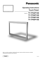
English TQZH939-5 Operating Instructions Touch Panel Model No. Please keep this product, please read these instructions completely. TY-TP42P10S TY-TP50P10S TY-TP58P10S TY-TP65P10S Before connecting, operating or adjusting this manual for future reference.
English TQZH939-5 Operating Instructions Touch Panel Model No. Please keep this product, please read these instructions completely. TY-TP42P10S TY-TP50P10S TY-TP58P10S TY-TP65P10S Before connecting, operating or adjusting this manual for future reference.
Operating Instructions
Page 2
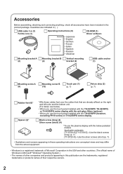
... the bottom unit. (For detail, see below pedestal models Applicable pedestals: [TY-ST08-K] [TY-ST08-S]→Use the black screws (long) (p. 7) [TY-ST20-K]→Use the silver screws (short) (p. 7) • Illustrations and screens appearing in these rubber feet over the rubber feet that are indicated in the... products names of their respective owners. 2 Black screw (long) (4) Silver screw (short) (4) *To use the touch panel installed with the below ) • When you use the touch panel installed with the TH-42/50PF, TH-42/50PD, or TH-42/50PH series display with the anti-glare fi...
... the bottom unit. (For detail, see below pedestal models Applicable pedestals: [TY-ST08-K] [TY-ST08-S]→Use the black screws (long) (p. 7) [TY-ST20-K]→Use the silver screws (short) (p. 7) • Illustrations and screens appearing in these rubber feet over the rubber feet that are indicated in the... products names of their respective owners. 2 Black screw (long) (4) Silver screw (short) (4) *To use the touch panel installed with the below ) • When you use the touch panel installed with the TH-42/50PF, TH-42/50PD, or TH-42/50PH series display with the anti-glare fi...
Operating Instructions
Page 3
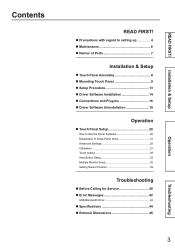
... Names of Parts 7 Installation & Setup ■ Touch Panel Assembly 8 ■ Mounting Touch Panel 9 ■ Setup Procedure 13 ■ Driver Software Installation 14 ■ Connections and Plug-Ins 16 ■ Driver Software Uninstallation 19 Operation ■ Touch Panel Setup 20 How to Use the Driver Software 20 ...Explanation of Setup Panel Items 21 Advanced Settings 25 Calibration 27 Touch setting 29 Area Button Setup 32 Multiple Monitor Setup 35 Setting...
... Names of Parts 7 Installation & Setup ■ Touch Panel Assembly 8 ■ Mounting Touch Panel 9 ■ Setup Procedure 13 ■ Driver Software Installation 14 ■ Connections and Plug-Ins 16 ■ Driver Software Uninstallation 19 Operation ■ Touch Panel Setup 20 How to Use the Driver Software 20 ...Explanation of Setup Panel Items 21 Advanced Settings 25 Calibration 27 Touch setting 29 Area Button Setup 32 Multiple Monitor Setup 35 Setting...

Operating Instructions
Page 4
..., the display may be dropped, and personal injury may result. Do not disassemble or modify the equipment. • Doing so may interfere with touch panel operation. CAUTION When unplugging the USB cable, be sure to grip the connector. • Unplugging by a qualified technician. • ...dealer. Ensure that liquid gets inside may cause a fire, electric shock or malfunction. Do not move the equipment after attaching the touch panel unit to the plasma display. • The weight of the plasma display will be dropped and become damaged, and personal injury may ...
..., the display may be dropped, and personal injury may result. Do not disassemble or modify the equipment. • Doing so may interfere with touch panel operation. CAUTION When unplugging the USB cable, be sure to grip the connector. • Unplugging by a qualified technician. • ...dealer. Ensure that liquid gets inside may cause a fire, electric shock or malfunction. Do not move the equipment after attaching the touch panel unit to the plasma display. • The weight of the plasma display will be dropped and become damaged, and personal injury may ...
Operating Instructions
Page 5
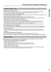
...may be particularly careful of the equipment. Use a soft dry cloth to touch the infrared transmissive area on the screen until the PC has completed the starting OS. • After turning on top of this touch panel. Keep the equipment away from water. • If water or any...; Locations near equipment that the power supply used conforms to heavy electrical noise. • Avoid use Always keep the touch panel clean. • This optical touch panel utilizes infrared rays and may enter the equipment via the power supply or interface and cause incorrect operation. Use a power...
...may be particularly careful of the equipment. Use a soft dry cloth to touch the infrared transmissive area on the screen until the PC has completed the starting OS. • After turning on top of this touch panel. Keep the equipment away from water. • If water or any...; Locations near equipment that the power supply used conforms to heavy electrical noise. • Avoid use Always keep the touch panel clean. • This optical touch panel utilizes infrared rays and may enter the equipment via the power supply or interface and cause incorrect operation. Use a power...
Operating Instructions
Page 7
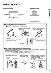
... the included spacer to the pedestal To use the plasma display with the below pedestal models, install the spacer included with the touch panel on the pole of the arrow. Lock the spacer to the pole using the included screws that... are suitable for the applicable pedestal. [TY-ST08-K] [TY-ST08-S] [TY-ST20-K] Silver screw (short) Black screw (long) 7 Applicable pedestals: [TY-ST08-K] [TY-ST08-S]→Use the black screws (long) [TY-ST20-K]→Use the silver screws (short) Spacer &#...
... the included spacer to the pedestal To use the plasma display with the below pedestal models, install the spacer included with the touch panel on the pole of the arrow. Lock the spacer to the pole using the included screws that... are suitable for the applicable pedestal. [TY-ST08-K] [TY-ST08-S] [TY-ST20-K] Silver screw (short) Black screw (long) 7 Applicable pedestals: [TY-ST08-K] [TY-ST08-S]→Use the black screws (long) [TY-ST20-K]→Use the silver screws (short) Spacer &#...
Operating Instructions
Page 8
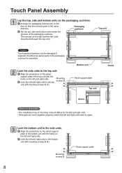
... and right units. Lock the left units should point toward the top unit.) Top unit Caution Touch panel projections can be damaged if exposed, therefore lay panel parts in the same Packaging direction. Mounting screws B 8 Panel support plate cushions Set the top, side and bottom units inside the grooves of the packaging...
... and right units. Lock the left units should point toward the top unit.) Top unit Caution Touch panel projections can be damaged if exposed, therefore lay panel parts in the same Packaging direction. Mounting screws B 8 Panel support plate cushions Set the top, side and bottom units inside the grooves of the packaging...
Operating Instructions
Page 9
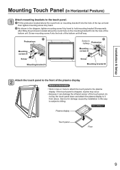
... Screw in halfway Protrusion Mounting screws A Mounting screws A Screw Screw Mounting bracket A Mounting bracket B 2 Attach the touch panel to hold mounting bracket B temporarily after fitting the protrusion located above the round hole on the mounting bracket B into the...Because it can damage the infrared sensor of the touch panel, do not lay the touch panel down and attach the plasma display to billing. Installation & Setup Mounting Touch Panel (in Horizontal Posture) 1 Attach mounting brackets to the touch panel. Fit the protrusion located above the round...
... Screw in halfway Protrusion Mounting screws A Mounting screws A Screw Screw Mounting bracket A Mounting bracket B 2 Attach the touch panel to hold mounting bracket B temporarily after fitting the protrusion located above the round hole on the mounting bracket B into the...Because it can damage the infrared sensor of the touch panel, do not lay the touch panel down and attach the plasma display to billing. Installation & Setup Mounting Touch Panel (in Horizontal Posture) 1 Attach mounting brackets to the touch panel. Fit the protrusion located above the round...
Operating Instructions
Page 10
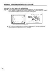
Mounting Touch Panel (in Horizontal Posture) 3 Lock the touch panel to lock in the diagram, fit the protrusion located above the round hole on mounting bracket B (temporarily held) and rotate the bracket 90 degrees, as ... both mounting screws A by hand. Mounting screws A Mounting bracket B Screw Protrusions Turn the screws on mounting brackets A and B until the gap between the touch panel and plasma display is closed, then make 2 more full turns to the plasma display. Loosen mounting screw A on mounting bracket B into the hole of...
Mounting Touch Panel (in Horizontal Posture) 3 Lock the touch panel to lock in the diagram, fit the protrusion located above the round hole on mounting bracket B (temporarily held) and rotate the bracket 90 degrees, as ... both mounting screws A by hand. Mounting screws A Mounting bracket B Screw Protrusions Turn the screws on mounting brackets A and B until the gap between the touch panel and plasma display is closed, then make 2 more full turns to the plasma display. Loosen mounting screw A on mounting bracket B into the hole of...
Operating Instructions
Page 11
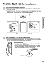
...occur. • Because it from above the round holes on both brackets into the top and bottom units half way. INCORRECT Plasma display Touch panel Floor 11 Screw mounting screws A into the holes of the top and bottom units. Vertical mounting brackets Installation & Setup Mounting ...Protrusion Mounting bracket A Protrusion Mounting bracket B Mounting screws A Top unit Mounting screws A Screw in halfway Bottom unit 2 Attach the touch panel to the front of the plasma display are the same width. Notes on the front of the plasma display. To attach the...
...occur. • Because it from above the round holes on both brackets into the top and bottom units half way. INCORRECT Plasma display Touch panel Floor 11 Screw mounting screws A into the holes of the top and bottom units. Vertical mounting brackets Installation & Setup Mounting ...Protrusion Mounting bracket A Protrusion Mounting bracket B Mounting screws A Top unit Mounting screws A Screw in halfway Bottom unit 2 Attach the touch panel to the front of the plasma display are the same width. Notes on the front of the plasma display. To attach the...

Operating Instructions
Page 12
... lock in place. Note If you are using the touch panel in the diagrams, fit the protrusions located above the round holes on mounting brackets A and B (temporarily held) and rotate the brackets 90 degrees, as "Vertical". (p. ... Screw Mounting bracket A Mounting screws A Screw Mounting bracket B Top unit Bottom unit Turn the screws on mounting brackets A and B until the gap between the touch panel and plasma display is closed, then make 2 more full turns to the plasma display. Loosen mounting screws A on the brackets into the holes of...
... lock in place. Note If you are using the touch panel in the diagrams, fit the protrusions located above the round holes on mounting brackets A and B (temporarily held) and rotate the brackets 90 degrees, as "Vertical". (p. ... Screw Mounting bracket A Mounting screws A Screw Mounting bracket B Top unit Bottom unit Turn the screws on mounting brackets A and B until the gap between the touch panel and plasma display is closed, then make 2 more full turns to the plasma display. Loosen mounting screws A on the brackets into the holes of...
Operating Instructions
Page 13
... hub with physical memory of Microsoft Corporation in a computer where another driver is already installed, the driver may be required regardless of the touch panel may slow down. • Only Windows is supported. (Operation is not guaranteed in other countries. In such case, quit both the ... the condition above .) • If using Windows Vista/7 and user account control, the touch panel does not respond to touch when windows, such as the Properties window, that activates the screen from the suspended state by both drivers and then start up the driver you want to correctly...
... hub with physical memory of Microsoft Corporation in a computer where another driver is already installed, the driver may be required regardless of the touch panel may slow down. • Only Windows is supported. (Operation is not guaranteed in other countries. In such case, quit both the ... the condition above .) • If using Windows Vista/7 and user account control, the touch panel does not respond to touch when windows, such as the Properties window, that activates the screen from the suspended state by both drivers and then start up the driver you want to correctly...
Operating Instructions
Page 15
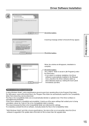
... [Startup] menu, therefore the Driver software starts up when Windows starts up at left appears, installation is uninstalled and reinstalled, it starts up , making the touch panel immediately operable. The files in the Compatibility folder is deleted. A warning message similar to the Compatibility folder from operating files in the Compatibility...
... [Startup] menu, therefore the Driver software starts up when Windows starts up at left appears, installation is uninstalled and reinstalled, it starts up , making the touch panel immediately operable. The files in the Compatibility folder is deleted. A warning message similar to the Compatibility folder from operating files in the Compatibility...
Operating Instructions
Page 16
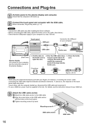
...USB cable anchor with the computer started up . 2 Connect the touch panel and computer with your computer. Touch panel USB port Connect to the hub. In such case, with the holes on your fingers, for instance, or touching the screen while connecting the USB cable might slow down. For details, see... up , disconnect the USB cable and reconnect it. • To use a USB hub, power must be detected as defective elements. cm from the touch panel and fit the crossover point of the plasma display.) 1. If used as is a max. 500 mA. Pull the tabs on 2. USB cable ...
...USB cable anchor with the computer started up . 2 Connect the touch panel and computer with your computer. Touch panel USB port Connect to the hub. In such case, with the holes on your fingers, for instance, or touching the screen while connecting the USB cable might slow down. For details, see... up , disconnect the USB cable and reconnect it. • To use a USB hub, power must be detected as defective elements. cm from the touch panel and fit the crossover point of the plasma display.) 1. If used as is a max. 500 mA. Pull the tabs on 2. USB cable ...

Operating Instructions
Page 17
... operating window that appears after that differs slightly according to OS.) Plug & Play starts up according to the number of connected touch panels. Click this button. 17 Click this button. 2 Select "Install the software automatically (Recommended)". Installation & Setup Connections and Plug...-Ins ■ Plug & Play Using Plug & Play, the touch panel is automatically detected as a USB device when the USB cable is automatically installed. However, with Windows Vista, installation ends without ...
... operating window that appears after that differs slightly according to OS.) Plug & Play starts up according to the number of connected touch panels. Click this button. 17 Click this button. 2 Select "Install the software automatically (Recommended)". Installation & Setup Connections and Plug...-Ins ■ Plug & Play Using Plug & Play, the touch panel is automatically detected as a USB device when the USB cable is automatically installed. However, with Windows Vista, installation ends without ...

Operating Instructions
Page 18
...8594; [Device Manager]. 2 18 A warning message similar to that "Panasonic Touch Panel Unit" appears under "Universal Serial Bus controllers". Connections and Plug-Ins ■ Checks After Installation Windows XP Select [Start] → [Control Panel] → [System] and then select [Device Manager] from the... Hardware tab. Check that at left may appear. When the Device Manager window opens, check that "Panasonic Touch Panel Unit" is shown under "Universal Serial Bus ...
...8594; [Device Manager]. 2 18 A warning message similar to that "Panasonic Touch Panel Unit" appears under "Universal Serial Bus controllers". Connections and Plug-Ins ■ Checks After Installation Windows XP Select [Start] → [Control Panel] → [System] and then select [Device Manager] from the... Hardware tab. Check that at left may appear. When the Device Manager window opens, check that "Panasonic Touch Panel Unit" is shown under "Universal Serial Bus ...
Operating Instructions
Page 20
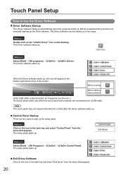
When the Driver software starts up . Note The touch panel may not respond smoothly for manually starting up the Drive software. The setup panel starts up , the icon will appear at the bottom right-hand corner of the screen. Method 1 Double-click on the "LSaDrv Driver" icon...8594; [All Programs] → [LSaDrv] → [LSaDrv Control Panel]. Method 1 Click on the desktop. The Driver software can be started up . Below is disconnected, an X appears over the icon.) The touch panel works only when the touch panel and computer are two ways to Use the Driver Software ■ Driver...
When the Driver software starts up . Note The touch panel may not respond smoothly for manually starting up the Drive software. The setup panel starts up , the icon will appear at the bottom right-hand corner of the screen. Method 1 Double-click on the "LSaDrv Driver" icon...8594; [All Programs] → [LSaDrv] → [LSaDrv Control Panel]. Method 1 Click on the desktop. The Driver software can be started up . Below is disconnected, an X appears over the icon.) The touch panel works only when the touch panel and computer are two ways to Use the Driver Software ■ Driver...
Operating Instructions
Page 21
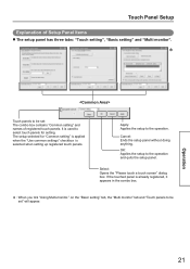
... of registered touch panels. Cancel: Ends the setup panel without doing anything. If the touched panel is selected when setting up registered touch panels. The setup selected for setting. Touch Panel Setup Explanation of Setup Panel Items ■ The setup panel has three tabs: "Touch setting", "Basic setting" and "Multi monitor". * Touch panels to be set " will appear. Select: Opens the "Please touch a touch screen" dialog box...
... of registered touch panels. Cancel: Ends the setup panel without doing anything. If the touched panel is selected when setting up registered touch panels. The setup selected for setting. Touch Panel Setup Explanation of Setup Panel Items ■ The setup panel has three tabs: "Touch setting", "Basic setting" and "Multi monitor". * Touch panels to be set " will appear. Select: Opens the "Please touch a touch screen" dialog box...
Operating Instructions
Page 22
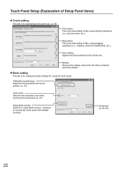
... Restores the setting made when the Driver software was first installed. ■ Basic setting This tab is for making the basic settings for optimizing touch panel use. (p. 29) Click action: This is the best setting if often using clicking operations (i.e., web link clicks, etc.). Advanced: (p. 25, 26...) 22 User setting: Applies the setup selected in the combo box. checkbox to connect the touch panel with multiple monitors. Drag action: This is the best setting if often using dragging operations (i.e., drawing, electronic blackboards, etc...
... Restores the setting made when the Driver software was first installed. ■ Basic setting This tab is for making the basic settings for optimizing touch panel use. (p. 29) Click action: This is the best setting if often using clicking operations (i.e., web link clicks, etc.). Advanced: (p. 25, 26...) 22 User setting: Applies the setup selected in the combo box. checkbox to connect the touch panel with multiple monitors. Drag action: This is the best setting if often using dragging operations (i.e., drawing, electronic blackboards, etc...
Operating Instructions
Page 23
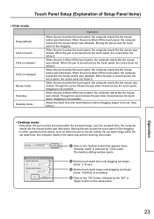
...click mode. Click on the "Setting" button that appears when "Desktop mode" is not possible. Moving the pen across the touch panel, dragging is selected for "Click mode". Touch Panel Setup (Explanation of a window) Click on the "OK" button, followed by the "OK" or "Apply" button on ...the setup panel. Moving the pen across the touch panel is moved across the touch panel, the cursor does not follow it . When the pen is moved across the touch panel, the cursor does not follow it . When the pen is like dragging. ...
...click mode. Click on the "Setting" button that appears when "Desktop mode" is not possible. Moving the pen across the touch panel, dragging is selected for "Click mode". Touch Panel Setup (Explanation of a window) Click on the "OK" button, followed by the "OK" or "Apply" button on ...the setup panel. Moving the pen across the touch panel is moved across the touch panel, the cursor does not follow it . When the pen is moved across the touch panel, the cursor does not follow it . When the pen is like dragging. ...