
WJPB65E01E User Guide
Page 1
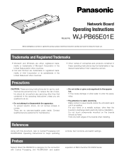
.../100 BASE-T ALARM OUT 2 ALARM OUT 1 Video Output BoaNrdew1oOrknlOy UT X-1 Network Board Operating Instructions Model No. Contact qualified service personnel for major operating controls, their respective owners. References Along with Central Processing Unit WJ-MPU955A and system expansion of their functions, and switch settings. To reduce the risk of the boards when installing. Put your hand on the boards directly by qualified service personnel only. Do not touch components mounted on a metallic...
.../100 BASE-T ALARM OUT 2 ALARM OUT 1 Video Output BoaNrdew1oOrknlOy UT X-1 Network Board Operating Instructions Model No. Contact qualified service personnel for major operating controls, their respective owners. References Along with Central Processing Unit WJ-MPU955A and system expansion of their functions, and switch settings. To reduce the risk of the boards when installing. Put your hand on the boards directly by qualified service personnel only. Do not touch components mounted on a metallic...

WJPB65E01E User Guide
Page 2
...-SX650 Series Operating Instructions for connection with Central Processing Unit WJ-MPU955A via an Ethernet network. LINK indicator ACT indicator w Alarm Output Ports 1, 2 (ALARM OUT 1, 2) Supplies alarm output signals controlled by Central Processing Unit WJ-MPU955A. Note: Refer to expand the system composition. LINK indicator: This indicator lights up when the matrix switcher receives or sends data through VS input signals supplied to 512 cameras and 64 monitors become connectable. t VS Output Connector (VS OUT) Supplies VS output signals to a PC...
...-SX650 Series Operating Instructions for connection with Central Processing Unit WJ-MPU955A via an Ethernet network. LINK indicator ACT indicator w Alarm Output Ports 1, 2 (ALARM OUT 1, 2) Supplies alarm output signals controlled by Central Processing Unit WJ-MPU955A. Note: Refer to expand the system composition. LINK indicator: This indicator lights up when the matrix switcher receives or sends data through VS input signals supplied to 512 cameras and 64 monitors become connectable. t VS Output Connector (VS OUT) Supplies VS output signals to a PC...

WJPB65E01E User Guide
Page 3
Dismount the OUT X-1 board from the front side. 5. Video Video Output Output Board Board 2 1 HHDDDRRA42T//TTAMM4NNLL84 HHDDDRRA13T//TTAMM3NNLL73 DATA 2 TMNL6 TMNL2 DATA 1 TMNTL1M/PNSLD5ATA TERM.ON TERM.OFF ON MODE MODE SIGNAL GND SIGNAL GND Network board OPERATE 650 Matrix Switcher WJ-SX 2. Video output main board Fixing brackets (x4) Screws (x8) 3. Mount the video output main board by hooking the board stoppers on the board stopper angles, and push down the board stoppers, and by fixing the screws...
Dismount the OUT X-1 board from the front side. 5. Video Video Output Output Board Board 2 1 HHDDDRRA42T//TTAMM4NNLL84 HHDDDRRA13T//TTAMM3NNLL73 DATA 2 TMNL6 TMNL2 DATA 1 TMNTL1M/PNSLD5ATA TERM.ON TERM.OFF ON MODE MODE SIGNAL GND SIGNAL GND Network board OPERATE 650 Matrix Switcher WJ-SX 2. Video output main board Fixing brackets (x4) Screws (x8) 3. Mount the video output main board by hooking the board stoppers on the board stopper angles, and push down the board stoppers, and by fixing the screws...

WJPB65E01E User Guide
Page 4
... Programs window will be displayed on a PC without Microsoft® .NET Framework 1.1, it will be displayed on the PC screen to install the Firmware update software on the PC screen. 2. Install the application again after uninstallation. I PC Connection An RS-232C crossing cable (9-pin D-sub) is used for installation of WJ-SX650 Series (WJ-PB65E01 installed) EXTENSION 3 IN 4 3 2 1 EXTENSION 2 IN MODE RS485 (CAMERA) MODE MODE RS485 (CAMERA) MODE IN C-3 VIDEO OUT 4 VIDEO OUT 3 VIDEO OUT 2 VIDEO OUT 1 ALARM...
... Programs window will be displayed on a PC without Microsoft® .NET Framework 1.1, it will be displayed on the PC screen to install the Firmware update software on the PC screen. 2. Install the application again after uninstallation. I PC Connection An RS-232C crossing cable (9-pin D-sub) is used for installation of WJ-SX650 Series (WJ-PB65E01 installed) EXTENSION 3 IN 4 3 2 1 EXTENSION 2 IN MODE RS485 (CAMERA) MODE MODE RS485 (CAMERA) MODE IN C-3 VIDEO OUT 4 VIDEO OUT 3 VIDEO OUT 2 VIDEO OUT 1 ALARM...

WJPB65E01E User Guide
Page 5
"File Selection" window is as follows. SERIAL port: Connected for version check TEST port: Connected for checking in Step 7. 6. The following directory. Firmware update software will be displayed on the PC screen. The factory default is displayed. Then, click "WJ-SX650 Series". The file is located in the "File Selection" window. Select "Start" - "Firmware version up , and the login window will start up software" - "Firmware update software" window is the procedure when using the Windows XP operating system...
"File Selection" window is as follows. SERIAL port: Connected for version check TEST port: Connected for checking in Step 7. 6. The following directory. Firmware update software will be displayed on the PC screen. The factory default is displayed. Then, click "WJ-SX650 Series". The file is located in the "File Selection" window. Select "Start" - "Firmware version up , and the login window will start up software" - "Firmware update software" window is the procedure when using the Windows XP operating system...

WJPB65E01E User Guide
Page 6
... change the factory default user name and password. Factory default: Auto Negotiation 6 I Features WJ-SX650 Series Initial Setup Tool is used for special configuration of default configuration is not required when a network card is installed.) WJ-SX650 Series Initial Setup Tool has the following configuration menus: • RS485 Camera This menu is impossible. The installation wizard will be changed by clicking "User setup" and changing the settings. • If the matrix switcher has Video Output Board 2, update the firmware...
... change the factory default user name and password. Factory default: Auto Negotiation 6 I Features WJ-SX650 Series Initial Setup Tool is used for special configuration of default configuration is not required when a network card is installed.) WJ-SX650 Series Initial Setup Tool has the following configuration menus: • RS485 Camera This menu is impossible. The installation wizard will be changed by clicking "User setup" and changing the settings. • If the matrix switcher has Video Output Board 2, update the firmware...

WJPB65E01E User Guide
Page 7
... Programs" - When download is complete, a message window is displayed. 4. I Starting Up Note: The following is as a file. i : Displays the settings page of SERIAL port. You may become unable to open on the PC screen. 2. "Panasonic" - "WJSX650 Series" - "WJ-SX650 Series Initial Setup Tool" window is displayed. The setting data will be displayed on a monitor, SETUP MENU will be connected to the PC. User Name: admin Password: sx650 3. Settings performed in SETUP MENU will be canceled and replaced...
... Programs" - When download is complete, a message window is displayed. 4. I Starting Up Note: The following is as a file. i : Displays the settings page of SERIAL port. You may become unable to open on the PC screen. 2. "Panasonic" - "WJSX650 Series" - "WJ-SX650 Series Initial Setup Tool" window is displayed. The setting data will be displayed on a monitor, SETUP MENU will be connected to the PC. User Name: admin Password: sx650 3. Settings performed in SETUP MENU will be canceled and replaced...

WJPB65E01E User Guide
Page 8
... Electric Industrial Co., Ltd. Specifications Ethernet Port: Alarm Output (ALARM OUT 1, 2) Alarm Output: VS Input: VS Output: Serial Port: Dimensions Network Board: 10/100BASE-T, RJ-45 x 1 Open collector output x 32, Max. 24 V DC, 100 mA 1 V[P-P]/75 Ω (VS IN) (VS OUT (THRU)): VS loop-thru output (VS OUT): 1 V[P-P]/75 Ω (VS) 9-pin D-sub connector x 1 355 mm (W) X 38 mm (H) X 134 mm (D) {14" (W) X 1-1/2" (H) X 5-3/10" (D)} Standard Accessories Operating Instructions (This Document 1 pc. Disposing...
... Electric Industrial Co., Ltd. Specifications Ethernet Port: Alarm Output (ALARM OUT 1, 2) Alarm Output: VS Input: VS Output: Serial Port: Dimensions Network Board: 10/100BASE-T, RJ-45 x 1 Open collector output x 32, Max. 24 V DC, 100 mA 1 V[P-P]/75 Ω (VS IN) (VS OUT (THRU)): VS loop-thru output (VS OUT): 1 V[P-P]/75 Ω (VS) 9-pin D-sub connector x 1 355 mm (W) X 38 mm (H) X 134 mm (D) {14" (W) X 1-1/2" (H) X 5-3/10" (D)} Standard Accessories Operating Instructions (This Document 1 pc. Disposing...


