
WJSX650 User Guide
Page 4
... a Recorder .....86 I Controlling from a PC 86 Glossary 87 Troubleshooting 89 I Matrix Switcher WJ-SX650 Series 89 I WJ-SX650 Series Administrator Console 93 I Power Cord, Connectors, and Power Plug 94 Specifications 95 I Matrix Switcher WJ-SX650 Series 95 I Card Cage WJ-SX650U 96 I Video Input Board WJ-PB65C32 96 I Video Output Board WJ-PB65M16 96 I Expansion Cable Kit WJ-CA65L20K/WJ-CA65L07K....97 I D-sub/BNC Video Cable WJ-CA68 97 Standard Accessories...
... a Recorder .....86 I Controlling from a PC 86 Glossary 87 Troubleshooting 89 I Matrix Switcher WJ-SX650 Series 89 I WJ-SX650 Series Administrator Console 93 I Power Cord, Connectors, and Power Plug 94 Specifications 95 I Matrix Switcher WJ-SX650 Series 95 I Card Cage WJ-SX650U 96 I Video Input Board WJ-PB65C32 96 I Video Output Board WJ-PB65M16 96 I Expansion Cable Kit WJ-CA65L20K/WJ-CA65L07K....97 I D-sub/BNC Video Cable WJ-CA68 97 Standard Accessories...

WJSX650 User Guide
Page 6
.... Moisture can work properly after turning on the boards directly by hand. Precautions CAUTION: These servicing instructions are for use , charge the built-in backup battery (lithium battery) by turning on a level surface. Replacement cost of the software provided with this apparatus is expressly prohibited. Put your settings and save them. To prevent electric shock, do not perform any power cord other than 5 cm...
.... Moisture can work properly after turning on the boards directly by hand. Precautions CAUTION: These servicing instructions are for use , charge the built-in backup battery (lithium battery) by turning on a level surface. Replacement cost of the software provided with this apparatus is expressly prohibited. Put your settings and save them. To prevent electric shock, do not perform any power cord other than 5 cm...

WJSX650 User Guide
Page 8
... installation of video input boards and video output boards) Video Input Board WJ-PB65C32 Video Output Board WJ-PB65M16 Expansion Cable Kit WJ-CA65L20K/WJ-CA65L07K D-sub/BNC Video Cable WJ-CA68 Features • Up to 256 cameras, 32 monitors connectable • Remote control of optional external devices If you connect a personal computer (PC) to this product, remote control of following models. User ID's and passwords are sequentially displayed on alarm event. • With recorder connection, recorder control such as recording...
... installation of video input boards and video output boards) Video Input Board WJ-PB65C32 Video Output Board WJ-PB65M16 Expansion Cable Kit WJ-CA65L20K/WJ-CA65L07K D-sub/BNC Video Cable WJ-CA68 Features • Up to 256 cameras, 32 monitors connectable • Remote control of optional external devices If you connect a personal computer (PC) to this product, remote control of following models. User ID's and passwords are sequentially displayed on alarm event. • With recorder connection, recorder control such as recording...

WJSX650 User Guide
Page 9
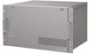
... is installed. (Video Input Board WJ-PB65C32) PULL POWER ON OFF RESET No. y Video Output Board* This is the illustration of WJ-SX650. This board controls monitors and alarm output signals. Major Operating Controls and Their Functions I WJ-SX650 Matrix Switcher/WJ-SX650U Card Cage G Front View w OPERATE OPERATE LED WILL BLINK IF COOLING FAN MALFUNCTIONS q 650 Matrix Switcher WJ-SX q Operation Indicator (OPERATE) • This indicator is lighting while power is supplied to the unit...
... is installed. (Video Input Board WJ-PB65C32) PULL POWER ON OFF RESET No. y Video Output Board* This is the illustration of WJ-SX650. This board controls monitors and alarm output signals. Major Operating Controls and Their Functions I WJ-SX650 Matrix Switcher/WJ-SX650U Card Cage G Front View w OPERATE OPERATE LED WILL BLINK IF COOLING FAN MALFUNCTIONS q 650 Matrix Switcher WJ-SX q Operation Indicator (OPERATE) • This indicator is lighting while power is supplied to the unit...

WJSX650 User Guide
Page 13
... Camera title setting is accepting a VS input signal, !3 supplies an output signal synchronizing the VS input signal. For PS·Data operations, refer to p. 85 OPERATION (OTHER THAN TERMINAL MODE) or the operating instructions of camera to which video loss has occurred) SUSPEND: Alarm is not accepting the VS input signal, !3 supplies an internal synchronization output signal. !4 Serial Port (SERIAL) Connects to 32: Monitor number Note: During monitor lock, monitor number is being selected, time and date are displayed. q w r e q Time and Date Information Current time...
... Camera title setting is accepting a VS input signal, !3 supplies an output signal synchronizing the VS input signal. For PS·Data operations, refer to p. 85 OPERATION (OTHER THAN TERMINAL MODE) or the operating instructions of camera to which video loss has occurred) SUSPEND: Alarm is not accepting the VS input signal, !3 supplies an internal synchronization output signal. !4 Serial Port (SERIAL) Connects to 32: Monitor number Note: During monitor lock, monitor number is being selected, time and date are displayed. q w r e q Time and Date Information Current time...

WJSX650 User Guide
Page 16
... using a recorder, Dsub/BNC Video Cable WJ-CA68 (Option) is the installation flow of cameras and recorders" in the diagram. • Use the following models for use 16 or less monitors. • External monitors directly connected to recorders can be mounted even some expansion slots are qualified to the number of electric shock do so. Installations CAUTION These servicing instructions are for system expansion. Check how many video input boards, video output boars, and card...
... using a recorder, Dsub/BNC Video Cable WJ-CA68 (Option) is the installation flow of cameras and recorders" in the diagram. • Use the following models for use 16 or less monitors. • External monitors directly connected to recorders can be mounted even some expansion slots are qualified to the number of electric shock do so. Installations CAUTION These servicing instructions are for system expansion. Check how many video input boards, video output boars, and card...

WJSX650 User Guide
Page 31
...) or "System" - For connection, use D-sub/BNC Video Cable WJ-CA68 (Option). "Recorder" of LCN's and recorder numbers for recorder connections. Camera input connectors (CAMERA IN 1 to 32) of this unit Video output ports (VIDEO OUT 1 to 4) of this Unit VIDEO OUT 1 to 4 ports are connected to 32) are performed in RECORDER of SETUP MENU (refer to 32 VIDEO OUT 4 The following is the association of WJ-SX650 Series Administrator Console. Note: Recorder settings are required for the...
...) or "System" - For connection, use D-sub/BNC Video Cable WJ-CA68 (Option). "Recorder" of LCN's and recorder numbers for recorder connections. Camera input connectors (CAMERA IN 1 to 32) of this unit Video output ports (VIDEO OUT 1 to 4) of this Unit VIDEO OUT 1 to 4 ports are connected to 32) are performed in RECORDER of SETUP MENU (refer to 32 VIDEO OUT 4 The following is the association of WJ-SX650 Series Administrator Console. Note: Recorder settings are required for the...

WJSX650 User Guide
Page 32
... channels supply video output signals from recorders to recorders. Setting changes are supplied from recorders. Video input signals are performed in "System" - "Recorder" - Recorder number (Unit Address (System)) 1 to 4 5 to 8 9 to 12 13 to 16 DATA port for recorder connection DATA 3 port of Video Output Board 1 (Factory default: HDR1) DATA 4 port of Video Output Board 1 (Factory default: HDR2) DATA 3 port of Video Output Board 2 (Factory default: HDR3) DATA 4 port of recorders if these camera input channels supply video output signals from system controllers. "DATA...
... channels supply video output signals from recorders to recorders. Setting changes are supplied from recorders. Video input signals are performed in "System" - "Recorder" - Recorder number (Unit Address (System)) 1 to 4 5 to 8 9 to 12 13 to 16 DATA port for recorder connection DATA 3 port of Video Output Board 1 (Factory default: HDR1) DATA 4 port of Video Output Board 1 (Factory default: HDR2) DATA 3 port of Video Output Board 2 (Factory default: HDR3) DATA 4 port of recorders if these camera input channels supply video output signals from system controllers. "DATA...

WJSX650 User Guide
Page 34
... cables (between this operation mode is applied. I Recorder Settings Be sure to the operating instructions of Recorder 16 (Unit Address (System): 16), select CAM NO. 999 for recorder connection. Notes: • In the factory default, the DATA 3 and 4 ports are available in the system. (Up to the same DATA port. "Event Program": ALARM (When setting QUICK for each recorder. switch setting. 34 The camera number settings must set w to p. 85 OPERATION (OTHER THAN TERMINAL MODE). However, when connecting system controllers to different DATA ports...
... cables (between this operation mode is applied. I Recorder Settings Be sure to the operating instructions of Recorder 16 (Unit Address (System): 16), select CAM NO. 999 for recorder connection. Notes: • In the factory default, the DATA 3 and 4 ports are available in the system. (Up to the same DATA port. "Event Program": ALARM (When setting QUICK for each recorder. switch setting. 34 The camera number settings must set w to p. 85 OPERATION (OTHER THAN TERMINAL MODE). However, when connecting system controllers to different DATA ports...

WJSX650 User Guide
Page 35
... controllers.) 4. When using system controllers in the PS·Data mode, camera numbers that are applicable for all the system controllers in the daisy chain. For system controllers in DATA PORT of SETUP MENU (refer to 4 system controllers can be set the MODE Switch #2 of DATA port of Video Output Board 2 cannot be selected differ depending on the CONTROLLER NO. Example: WV-CU950/650: 1 to 999 WV-CU360C/CJ: 1 to the operating instructions of Video Output...
... controllers.) 4. When using system controllers in the PS·Data mode, camera numbers that are applicable for all the system controllers in the daisy chain. For system controllers in DATA PORT of SETUP MENU (refer to 4 system controllers can be set the MODE Switch #2 of DATA port of Video Output Board 2 cannot be selected differ depending on the CONTROLLER NO. Example: WV-CU950/650: 1 to 999 WV-CU360C/CJ: 1 to the operating instructions of Video Output...

WJSX650 User Guide
Page 37
... STATUS is adjusted on 4 monitors. Note: "Alarm Recover Input 1 to 16" can be checked on the hour. SYSTEM STATUS will be used as "Alarm Monitor Reset". (Refer to 4. Time is being displayed on the supplied CD-ROM). 37 Press the F1 button. Select one of Monitor 1 to 4. (Refer to Serial (RS-232C) Connector Command Reference (PDF file on monitors, normal operations and alarm control are highlighted...
... STATUS is adjusted on 4 monitors. Note: "Alarm Recover Input 1 to 16" can be checked on the hour. SYSTEM STATUS will be used as "Alarm Monitor Reset". (Refer to 4. Time is being displayed on the supplied CD-ROM). 37 Press the F1 button. Select one of Monitor 1 to 4. (Refer to Serial (RS-232C) Connector Command Reference (PDF file on monitors, normal operations and alarm control are highlighted...

WJSX650 User Guide
Page 38
... Camera Number) settings. "VD2/DATA/Cable Comp." Example: camera x 150, recorder x 10, monitor x 32, and system controller x 2 (Terminal mode) 1. "System" - Notes: • Set LCN parameters for these channels accept video input signals from recorders to the DATA port and CAM (CAMERA IN connectors) currently displayed. "DATA Port" DATA PORT (Refer to 256: Delete the LCN parameters. CAM151 to 160: Set VD2 and DATA to OFF. (Video input signals are properly connected to these parameters when using PS·Data system controllers, etc. 38 Recorder...
... Camera Number) settings. "VD2/DATA/Cable Comp." Example: camera x 150, recorder x 10, monitor x 32, and system controller x 2 (Terminal mode) 1. "System" - Notes: • Set LCN parameters for these channels accept video input signals from recorders to the DATA port and CAM (CAMERA IN connectors) currently displayed. "DATA Port" DATA PORT (Refer to 256: Delete the LCN parameters. CAM151 to 160: Set VD2 and DATA to OFF. (Video input signals are properly connected to these parameters when using PS·Data system controllers, etc. 38 Recorder...

WJSX650 User Guide
Page 41
.... I Starting Up 1. u : Displays the existence of video input board and software version of WJ-SX650 Series Administrator Console. !1 These buttons are clicked when setting categories are selected. !2 Selects a tab screen. The factory default is displayed. e : Creates the initial settings. y : Opens the settings guidance window. I Window Details !2 !1 !3 G Tool Bar q : Downloads the current setup data of the unit to the PC. "WJSX650 Series" - "Download" window will be displayed on a monitor, SETUP MENU will be canceled and replaced by...
.... I Starting Up 1. u : Displays the existence of video input board and software version of WJ-SX650 Series Administrator Console. !1 These buttons are clicked when setting categories are selected. !2 Selects a tab screen. The factory default is displayed. e : Creates the initial settings. y : Opens the settings guidance window. I Window Details !2 !1 !3 G Tool Bar q : Downloads the current setup data of the unit to the PC. "WJSX650 Series" - "Download" window will be displayed on a monitor, SETUP MENU will be canceled and replaced by...

WJSX650 User Guide
Page 44
... 16: Total recorder number Note: When camera input channels to supply video input signals from the SERIAL port only as a serial command.) Note: To activate serial command transmission, set to "RS485" in "Communication" - To change the setting, you need to delete the alarm event setting or change the Display Mode if an alarm event has been associated with a numeric other than "0". • 99999 is not available. View: An operator can display the selected camera image on the...
... 16: Total recorder number Note: When camera input channels to supply video input signals from the SERIAL port only as a serial command.) Note: To activate serial command transmission, set to "RS485" in "Communication" - To change the setting, you need to delete the alarm event setting or change the Display Mode if an alarm event has been associated with a numeric other than "0". • 99999 is not available. View: An operator can display the selected camera image on the...

WJSX650 User Guide
Page 53
... (INPUT BOARD=8) • UNIT Select the unit numbers for the connected RS-485 cameras. 1 to p. 50.) 53 OFF: Not sends the VD2 timing pulse with the camera output signal. • DATA Select ON or OFF. (The factory default is ON.) ON: Sends the control data with the camera output signal via the coaxial cable. • CABLE Perform the settings to compensate for camera input channels accepting video input signals from recorders. To activate RS-485 camera connections, change the settings in the RECORDER menu...
... (INPUT BOARD=8) • UNIT Select the unit numbers for the connected RS-485 cameras. 1 to p. 50.) 53 OFF: Not sends the VD2 timing pulse with the camera output signal. • DATA Select ON or OFF. (The factory default is ON.) ON: Sends the control data with the camera output signal via the coaxial cable. • CABLE Perform the settings to compensate for camera input channels accepting video input signals from recorders. To activate RS-485 camera connections, change the settings in the RECORDER menu...

WJSX650 User Guide
Page 85
... cannot control the following is the restrictions of recorder. • Alarm Alarm ACK, Alarm Individual Reset, and Alarm Monitor Reset are as a PS·Data operator. Enter the system function number by entering the user ID and password registered in the PS·Data mode, a web browser accessing the recorder, or a PC. User level setting is performed in the PS·Data mode, check the software version. Operation (Other than Terminal Mode) This...
... cannot control the following is the restrictions of recorder. • Alarm Alarm ACK, Alarm Individual Reset, and Alarm Monitor Reset are as a PS·Data operator. Enter the system function number by entering the user ID and password registered in the PS·Data mode, a web browser accessing the recorder, or a PC. User level setting is performed in the PS·Data mode, check the software version. Operation (Other than Terminal Mode) This...

WJSX650 User Guide
Page 87
... DATA ports set to PSD are also serial alarms. (Refer to p. 86.) Video loss: Alarm input signals which are displayed on the monitor. Alarm schedule: Function to coaxial cable disconnections or camera troubles. Alarm suspension: Operation to suspend alarm occurrence to display the images of Panasonic cameras on associated monitors, can be attenuated. 87 VD2: Timing pulse to the unit. Recorder number: Unit Address (System) numbers (Recorder 1 to p. 56. Refer to 16) set for recorders in SETUP MENU of recorders for recorder selection. Auto...
... DATA ports set to PSD are also serial alarms. (Refer to p. 86.) Video loss: Alarm input signals which are displayed on the monitor. Alarm schedule: Function to coaxial cable disconnections or camera troubles. Alarm suspension: Operation to suspend alarm occurrence to display the images of Panasonic cameras on associated monitors, can be attenuated. 87 VD2: Timing pulse to the unit. Recorder number: Unit Address (System) numbers (Recorder 1 to p. 56. Refer to 16) set for recorders in SETUP MENU of recorders for recorder selection. Auto...

WJSX650 User Guide
Page 89
... (or BUSY)" is blinking (or lighting), monitor control is deteriorating. Consult the dealer for replace- 6 ment. socket of the unit. When using a modular cable not supplied to the AC outlet. - • Check if the power cord is properly connected to the system controller, apply the 95 6-conductor type. • Check if the operation mode and controller numbers are 34 properly set. • Check the DATA port setting (TMNL or PSD...
... (or BUSY)" is blinking (or lighting), monitor control is deteriorating. Consult the dealer for replace- 6 ment. socket of the unit. When using a modular cable not supplied to the AC outlet. - • Check if the power cord is properly connected to the system controller, apply the 95 6-conductor type. • Check if the operation mode and controller numbers are 34 properly set. • Check the DATA port setting (TMNL or PSD...

WJSX650 User Guide
Page 90
... accept video input signals from recorder. 50 • Check the level settings or camera access setting. 55 • Check the LCD (or LED) display or indicators of system controller. If a receiver is being used, check if the power is supplied to the camera. 27 • Check if the selected camera input channel is not set for RS-485 communication in VD2/DATA/CABLE COMPENSATION of SETUP MENU. 53 • Check if the camera input channel...
... accept video input signals from recorder. 50 • Check the level settings or camera access setting. 55 • Check the LCD (or LED) display or indicators of system controller. If a receiver is being used, check if the power is supplied to the camera. 27 • Check if the selected camera input channel is not set for RS-485 communication in VD2/DATA/CABLE COMPENSATION of SETUP MENU. 53 • Check if the camera input channel...

WJSX650 User Guide
Page 93
..., timer event, alarm event, recorder, or camera input channel. mark (in a triangle) is displayed in "System" - "Auto Login/Auto Logout". • Start time of "Schedule" - "!" "DATA Port". Cannot set . "Timer Event". • Check if Control is displayed in "System" - "!" Delete alarm event 66 settings with higher priority has been set Control to the camera input channel in gray, and you cannot change the monitor display modes of the event. • Check if the monitor is associated. "Logical Camera Number...
..., timer event, alarm event, recorder, or camera input channel. mark (in a triangle) is displayed in "System" - "Auto Login/Auto Logout". • Start time of "Schedule" - "!" "DATA Port". Cannot set . "Timer Event". • Check if Control is displayed in "System" - "!" Delete alarm event 66 settings with higher priority has been set Control to the camera input channel in gray, and you cannot change the monitor display modes of the event. • Check if the monitor is associated. "Logical Camera Number...


