
Operating Instructions
Page 1
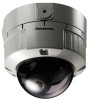
No model number suffix is shown above. Before attempting to connect or operate this product, please read these instructions carefully and save this manual. Color CCTV Cameras Operating Instructions Model No. WV-CW484 Series (Lens is option.) WV-CW484F is shown in this manual for future use.
No model number suffix is shown above. Before attempting to connect or operate this product, please read these instructions carefully and save this manual. Color CCTV Cameras Operating Instructions Model No. WV-CW484 Series (Lens is option.) WV-CW484F is shown in this manual for future use.
Operating Instructions
Page 4
... CLAIM OR ACTION FOR DAMAGES, BROUGHT BY ANY PERSON OR ORGANIZATION BEING A PHOTOGENIC SUBJECT, DUE TO VIOLATION OF PRIVACY WITH THE RESULT OF THAT SURVEILLANCE-CAMERA'S PICTURE, INCLUDING SAVED DATA, FOR SOME REASON, BECOMES PUBLIC OR IS USED FOR THE PURPOSE OTHER THAN SURVEILLANCE. 4 NANCE OF THE PRODUCT, FOR THE CASES...
... CLAIM OR ACTION FOR DAMAGES, BROUGHT BY ANY PERSON OR ORGANIZATION BEING A PHOTOGENIC SUBJECT, DUE TO VIOLATION OF PRIVACY WITH THE RESULT OF THAT SURVEILLANCE-CAMERA'S PICTURE, INCLUDING SAVED DATA, FOR SOME REASON, BECOMES PUBLIC OR IS USED FOR THE PURPOSE OTHER THAN SURVEILLANCE. 4 NANCE OF THE PRODUCT, FOR THE CASES...
Operating Instructions
Page 5
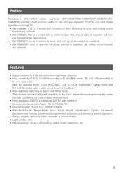
.../remote), automatic adjustment at BW/CL transition Setup using an optional system controller is optional. Features • Super Dynamic 3: 128x with x2 varifocal lens. Preface Panasonic's WV-CW484 series cameras (WV-CW484F/WV-CW484S/WV-CW484FK/WVCW484SK) introduce high picture quality by use of Super-Dynamic 1/3 inch CCD and digital signal processing LSIs. •...
.../remote), automatic adjustment at BW/CL transition Setup using an optional system controller is optional. Features • Super Dynamic 3: 128x with x2 varifocal lens. Preface Panasonic's WV-CW484 series cameras (WV-CW484F/WV-CW484S/WV-CW484FK/WVCW484SK) introduce high picture quality by use of Super-Dynamic 1/3 inch CCD and digital signal processing LSIs. •...

Operating Instructions
Page 7
... with the chemical cloth product. 7 Precautions This apparatus has no user-serviceable parts inside. To keep on /off when cleaning of picture quality. Handle the camera with a dry cloth. Do not rub the edges of this product when using with stable performance • Parts of this product may deteriorate and it... damaged by improper handling or storage. Smear Bright subject Do not drop metallic parts through slots. Turn the power off ) With the optional Heater Unit WV-CW4H, this may cause discoloration. To prevent electric shock, do not remove screws or covers.
... with the chemical cloth product. 7 Precautions This apparatus has no user-serviceable parts inside. To keep on /off when cleaning of picture quality. Handle the camera with a dry cloth. Do not rub the edges of this product when using with stable performance • Parts of this product may deteriorate and it... damaged by improper handling or storage. Smear Bright subject Do not drop metallic parts through slots. Turn the power off ) With the optional Heater Unit WV-CW4H, this may cause discoloration. To prevent electric shock, do not remove screws or covers.
Operating Instructions
Page 8
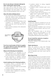
... temperature is not within -10 °C - +50 °C {14 °F - 122 °F}. • Locations subject to clean the camera when dirty. Do not use Mounting Bracket WV-Q114 (option) or Ceiling Mount Bracket WV-Q166 (option). When the dirt is necessary to procure screws or bolts to dehumidify. • Never seal the surfaces...
... temperature is not within -10 °C - +50 °C {14 °F - 122 °F}. • Locations subject to clean the camera when dirty. Do not use Mounting Bracket WV-Q114 (option) or Ceiling Mount Bracket WV-Q166 (option). When the dirt is necessary to procure screws or bolts to dehumidify. • Never seal the surfaces...
Operating Instructions
Page 9
The input power source is 24 V AC or 12 V DC. 9 Consumable parts Contact your dealer for replacement of the following part when the time comes: Cooling fan needs replacement after around 30 000 hours of operation. Do not operate the camera beyond the specified temperature, humidity or power source ratings. Use the camera at temperatures within -10 °C to +50 °C {14 °F - 122 °F}, and humidity below 90 %.
The input power source is 24 V AC or 12 V DC. 9 Consumable parts Contact your dealer for replacement of the following part when the time comes: Cooling fan needs replacement after around 30 000 hours of operation. Do not operate the camera beyond the specified temperature, humidity or power source ratings. Use the camera at temperatures within -10 °C to +50 °C {14 °F - 122 °F}, and humidity below 90 %.

Operating Instructions
Page 11
...!7 RIGHT button [(RIGHT), NEAR] Moves the cursor to p. 18 for the Input Terminal. e Dome cover r Focus lock lever (WV-CW484F, WV-CW484S) Fixes the focus position. i Panning table Adjusts the panning angle of the monitor. Make sure to connect the grounding lead to 12 ...(UP) Moves the cursor upward and selects items in the setup menu. t Zoom lock lever (WV-CW484F, WV-CW484S) Fixes the zoom position. o Panning lock screw Fixes the panning position. !0 Camera lock screw Fixes the camera and camera attachment. !1 Monitor output Jack (3.5 diam. q Power cable (12 V DC or 24 V ...
...!7 RIGHT button [(RIGHT), NEAR] Moves the cursor to p. 18 for the Input Terminal. e Dome cover r Focus lock lever (WV-CW484F, WV-CW484S) Fixes the focus position. i Panning table Adjusts the panning angle of the monitor. Make sure to connect the grounding lead to 12 ...(UP) Moves the cursor upward and selects items in the setup menu. t Zoom lock lever (WV-CW484F, WV-CW484S) Fixes the zoom position. o Panning lock screw Fixes the panning position. !0 Camera lock screw Fixes the camera and camera attachment. !1 Monitor output Jack (3.5 diam. q Power cable (12 V DC or 24 V ...
Operating Instructions
Page 12
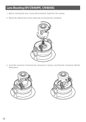
Mount the optional lens to the camera by turning the lens clockwise. 3. Insert the connector of lens into the connector of camera, and bind the connectors with the fixing band. 12 Before mounting the lens, remove the protection sheet from the camera. 2. Lens Mounting (WV-CW484FK, CW484SK) 1.
Mount the optional lens to the camera by turning the lens clockwise. 3. Insert the connector of lens into the connector of camera, and bind the connectors with the fixing band. 12 Before mounting the lens, remove the protection sheet from the camera. 2. Lens Mounting (WV-CW484FK, CW484SK) 1.

Operating Instructions
Page 13
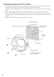
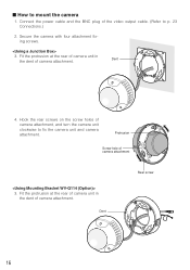
Junction box 46 mm {1-13/16"} 83.5 mm {3-5/16"} Camera attachment (provided) 13 x 4 in.) built in use. Recommended tightening torque is not strong enough, reinforce and strengthen it or use Mounting Bracket WV-Q114 (option) or Ceiling Mount Bracket WV-Q166 (option). • Required pull-out capacity of the bracket in a wall or ceiling...
Junction box 46 mm {1-13/16"} 83.5 mm {3-5/16"} Camera attachment (provided) 13 x 4 in.) built in use. Recommended tightening torque is not strong enough, reinforce and strengthen it or use Mounting Bracket WV-Q114 (option) or Ceiling Mount Bracket WV-Q166 (option). • Required pull-out capacity of the bracket in a wall or ceiling...
Operating Instructions
Page 14
... exit unscrewing the lid by use of the arrow marks faces upward. Cable access hole for 3/4" pipe 85 mm {3-3/8"} Cable access hole for 3/4" pipe WV-Q114 TOP 51 mm {2"} 85 mm {3-3/8"} TOP Bracket center Drain hole* Sideway cable exit * For wall mounting, face the drain hole downward. 14... G Using Mounting Bracket WV-Q114 (Option) • Secure the optional camera mounting bracket to wall or ceiling, and fix the provided camera attachment to the mounting bracket. (Refer to the cable access hole on the bottom of the ...
... exit unscrewing the lid by use of the arrow marks faces upward. Cable access hole for 3/4" pipe 85 mm {3-3/8"} Cable access hole for 3/4" pipe WV-Q114 TOP 51 mm {2"} 85 mm {3-3/8"} TOP Bracket center Drain hole* Sideway cable exit * For wall mounting, face the drain hole downward. 14... G Using Mounting Bracket WV-Q114 (Option) • Secure the optional camera mounting bracket to wall or ceiling, and fix the provided camera attachment to the mounting bracket. (Refer to the cable access hole on the bottom of the ...
Operating Instructions
Page 15
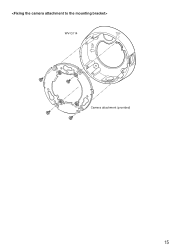
WV-Q114 TOP TOP Camera attachment (provided) 15
WV-Q114 TOP TOP Camera attachment (provided) 15
Operating Instructions
Page 16
... 3. Dent 4. Protrusion Screw hole of camera attachment, and turn the camera unit clockwise to fix the camera unit and camera attachment. Fit the protrusion at the rear of camera unit in the dent of the video output cable. (Refer to mount the camera 1. Dent TOP Rear screw 16 Connect the... power cable and the BNC plug of camera attachment. Fit the protrusion at the rear of camera unit in the dent of camera attachment. I How to p. 23 Connections.) 2. Hook ...
... 3. Dent 4. Protrusion Screw hole of camera attachment, and turn the camera unit clockwise to fix the camera unit and camera attachment. Fit the protrusion at the rear of camera unit in the dent of the video output cable. (Refer to mount the camera 1. Dent TOP Rear screw 16 Connect the... power cable and the BNC plug of camera attachment. Fit the protrusion at the rear of camera unit in the dent of camera attachment. I How to p. 23 Connections.) 2. Hook ...
Operating Instructions
Page 17
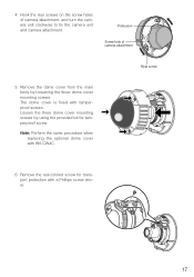
... The dome cover is fixed with tamperproof screws. Remove the dome cover from the main body by using the provided bit for transport protection with WV-CW4C. Loosen the three dome cover mounting screws by loosening the three dome cover mounting screws. Hook the rear screws on the screw holes of...
... The dome cover is fixed with tamperproof screws. Remove the dome cover from the main body by using the provided bit for transport protection with WV-CW4C. Loosen the three dome cover mounting screws by loosening the three dome cover mounting screws. Hook the rear screws on the screw holes of...
Operating Instructions
Page 18
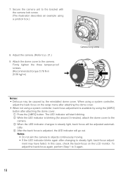
... start blinking. To adjust the back-focus again, perform Step 1 to p. 21.) 9. Secure the camera unit to the camera. Attach the dome cover to the bracket with the camera lock screw. (The illustration describes an example using a system controller, back focus adjustment is available by ...• When not using a junction box.) 8. Firmly tighten the three tamper-proof screws. (Recommended torque 0.78 N·m {0.08 kgf·m} Camera fixing screw Notes: • Defocus may be adjusted automati- cally. w While the LED indicator is adjusted, the LED indicator will go out. When...
... start blinking. To adjust the back-focus again, perform Step 1 to p. 21.) 9. Secure the camera unit to the camera. Attach the dome cover to the bracket with the camera lock screw. (The illustration describes an example using a system controller, back focus adjustment is available by ...• When not using a junction box.) 8. Firmly tighten the three tamper-proof screws. (Recommended torque 0.78 N·m {0.08 kgf·m} Camera fixing screw Notes: • Defocus may be adjusted automati- cally. w While the LED indicator is adjusted, the LED indicator will go out. When...
Operating Instructions
Page 19
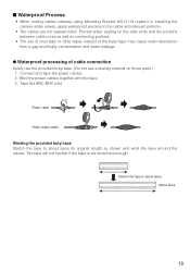
... water absorption from a gap and finally condensation and water leakage. About twice 19 I Waterproof Process • When routing cables sideway using Mounting Bracket WV-Q114 (option) or installing the camera under eaves, apply waterproof process to about twice its original length as connecting portions. • The use a sealing material on those parts...
... water absorption from a gap and finally condensation and water leakage. About twice 19 I Waterproof Process • When routing cables sideway using Mounting Bracket WV-Q114 (option) or installing the camera under eaves, apply waterproof process to about twice its original length as connecting portions. • The use a sealing material on those parts...
Operating Instructions
Page 20
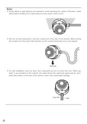
... attach a pipe fitting to the bracket to avoid exposing the cables. Drain hole Pipe 20 When pulling the conduit out of the side of the camera, which may cause a short circuit. • Run the conduit downward or pull the conduit out of the side of the bracket. Download • For wall...
... attach a pipe fitting to the bracket to avoid exposing the cables. Drain hole Pipe 20 When pulling the conduit out of the side of the camera, which may cause a short circuit. • Run the conduit downward or pull the conduit out of the side of the bracket. Download • For wall...
Operating Instructions
Page 21
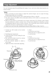
...zoom and focus after adjusting. 75° Tilting lock screw Azimuth (Angle adjuster) 3. Straight type plugs are not available. • Do not hold the camera by lens unit to adjust panning, tilting, or azimuth. • The video output to obtain a proper focus. Focus • Unlock the focus lever.... • Move the lever to adjust the camera images, use , and blooming or smear is connected to the monitor output jack, ELC (Electric Light Control) becomes effective to the BNC will be...
...zoom and focus after adjusting. 75° Tilting lock screw Azimuth (Angle adjuster) 3. Straight type plugs are not available. • Do not hold the camera by lens unit to adjust panning, tilting, or azimuth. • The video output to obtain a proper focus. Focus • Unlock the focus lever.... • Move the lever to adjust the camera images, use , and blooming or smear is connected to the monitor output jack, ELC (Electric Light Control) becomes effective to the BNC will be...

Operating Instructions
Page 22
... • The bar graph will be out-of-focus depending on the focal depth of -focus than under visible light. (However, the camera will not change the focus according to the illumination change when the focus had been adjusted once.) Before adjusting the varifocal lens, reset the ... When the "BACK-FOCUS SETUP" page is displayed and "AUTO" or "PRESET" is selected for "C/L" ↔ B/W" using the operation buttons on the camera, the camera can automatically focus on the monitor for 2 seconds or more, or by simultaneously pressing the [LEFT] and [RIGHT] buttons after pressing the [SET] button...
... • The bar graph will be out-of-focus depending on the focal depth of -focus than under visible light. (However, the camera will not change the focus according to the illumination change when the focus had been adjusted once.) Before adjusting the varifocal lens, reset the ... When the "BACK-FOCUS SETUP" page is displayed and "AUTO" or "PRESET" is selected for "C/L" ↔ B/W" using the operation buttons on the camera, the camera can automatically focus on the monitor for 2 seconds or more, or by simultaneously pressing the [LEFT] and [RIGHT] buttons after pressing the [SET] button...
Operating Instructions
Page 23
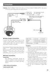
... length is unavailable. Be sure to connect the grounding lead to the monitor or other system device with NEC 725-51. • Wire Colors & Functions Camera power cable Wire Color Brown Blue Green/Yellow 24 V AC 24 V AC (L) 24 V AC (N) To GND 12 V DC Positive Negative Cautions: • Be sure... to connect the GND (grounding) lead of the camera and grounding terminal of the power supply when using 12 V DC power supply, the optional heater unit is shown in accordance with the procured coaxial...
... length is unavailable. Be sure to connect the grounding lead to the monitor or other system device with NEC 725-51. • Wire Colors & Functions Camera power cable Wire Color Brown Blue Green/Yellow 24 V AC 24 V AC (L) 24 V AC (N) To GND 12 V DC Positive Negative Cautions: • Be sure... to connect the GND (grounding) lead of the camera and grounding terminal of the power supply when using 12 V DC power supply, the optional heater unit is shown in accordance with the procured coaxial...
Operating Instructions
Page 24
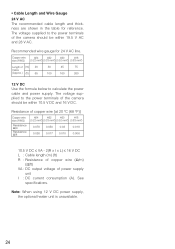
The voltage supplied to the power terminals of the camera should be within 19.5 V AC and 28 V AC. See specifications. The voltage supplied to calculate the power cable and power supply. Copper wire #24 #22 #... power terminals of power supply unit I x L) ≤ 16 V DC L : Cable length (m) (ft) R : Resistance of copper wire (Ω/m) (Ω/ft) VA : DC output voltage of the camera should be within 10.5 V DC and 16 V DC. Resistance of copper wire [at 20 °C (68 °F)] Copper wire size (AWG) Resistance Ω/m Resistance Ω...
The voltage supplied to the power terminals of the camera should be within 19.5 V AC and 28 V AC. See specifications. The voltage supplied to calculate the power cable and power supply. Copper wire #24 #22 #... power terminals of power supply unit I x L) ≤ 16 V DC L : Cable length (m) (ft) R : Resistance of copper wire (Ω/m) (Ω/ft) VA : DC output voltage of the camera should be within 10.5 V DC and 16 V DC. Resistance of copper wire [at 20 °C (68 °F)] Copper wire size (AWG) Resistance Ω/m Resistance Ω...


