
Operating Instructions
Page 1
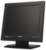
Before attempting to connect or operate this product, please read these instructions carefully and save this manual for future use. Video Monitor Operating Instructions WV-LC1700 Model Nos. WV-LC1900 Video Monitor WV-LC1900 This illustration represents WV-LC1900.
Before attempting to connect or operate this product, please read these instructions carefully and save this manual for future use. Video Monitor Operating Instructions WV-LC1700 Model Nos. WV-LC1900 Video Monitor WV-LC1900 This illustration represents WV-LC1900.

Operating Instructions
Page 2
... maintenance (servicing) instructions in the ON position. The exclamation point within the product's enclosure that may be found to comply with the instruction manual, may be required to the presence of this equipment. Any changes or modifications not expressly approved by qualified service personnel or system installers. • The connections should comply with or without ON-OFF switches have power supplied to...
... maintenance (servicing) instructions in the ON position. The exclamation point within the product's enclosure that may be found to comply with the instruction manual, may be required to the presence of this equipment. Any changes or modifications not expressly approved by qualified service personnel or system installers. • The connections should comply with or without ON-OFF switches have power supplied to...
Operating Instructions
Page 3
... by the manufacturer. 12) Use only with the cart, stand, tripod, bracket, or table specified by the manufacturer, or sold with dry cloth. 7) Do not block any heat sources such as power-supply cord or plug is required when the apparatus has been damaged in accordance with the manufacturer's instructions. 8) Do not install near water. 6) Clean only with the apparatus...
... by the manufacturer. 12) Use only with the cart, stand, tripod, bracket, or table specified by the manufacturer, or sold with dry cloth. 7) Do not block any heat sources such as power-supply cord or plug is required when the apparatus has been damaged in accordance with the manufacturer's instructions. 8) Do not install near water. 6) Clean only with the apparatus...
Operating Instructions
Page 5
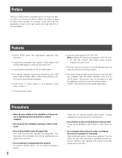
... ...6 Major Operating Instructions and Their Functions 8 Front View ...8 Rear View ...8 Installations ...10 Installation this monitor in a rack 10 Connections ...12 Connection Example ...12 Camera Connection ...13 Connection with Two or More Video Monitors 13 Digital Disk Recorder Connection 13 PC Connection ...13 Power-On ...14 Audio Volume Control ...15 Video Adjustment and Setup ...15 Video Adjustment (Video Input, S-Video Input 15 Video Adjustment (PC Input Connector 17 Setting of PC Input ...18 Language Setup ...19 Troubleshooting ...20 Specifications ...21 Appearance ...22...
... ...6 Major Operating Instructions and Their Functions 8 Front View ...8 Rear View ...8 Installations ...10 Installation this monitor in a rack 10 Connections ...12 Connection Example ...12 Camera Connection ...13 Connection with Two or More Video Monitors 13 Digital Disk Recorder Connection 13 PC Connection ...13 Power-On ...14 Audio Volume Control ...15 Video Adjustment and Setup ...15 Video Adjustment (Video Input, S-Video Input 15 Video Adjustment (PC Input Connector 17 Setting of PC Input ...18 Language Setup ...19 Troubleshooting ...20 Specifications ...21 Appearance ...22...
Operating Instructions
Page 6
... (V) (WV-LC1900) LCD panel. Preface This is a video monitor provided with larger power source, replace the power cord. • This unit can be automatically adjusted. • Audio input x1, audio output x1, and speaker output (max. 0.5 W) x 1 • On-screen setup menu • Auto-volt power supply from VGA (640 x 480) to water or moisture. To prevent electric shock, do not remove screws or covers. 6 There are compliant with high-speed response, high resolution • Supporting composite video signal, S-video signal, and analog RGB signal...
... (V) (WV-LC1900) LCD panel. Preface This is a video monitor provided with larger power source, replace the power cord. • This unit can be automatically adjusted. • Audio input x1, audio output x1, and speaker output (max. 0.5 W) x 1 • On-screen setup menu • Auto-volt power supply from VGA (640 x 480) to water or moisture. To prevent electric shock, do not remove screws or covers. 6 There are compliant with high-speed response, high resolution • Supporting composite video signal, S-video signal, and analog RGB signal...
Operating Instructions
Page 7
... its specified temperature, humidity, or power source ratings. Failure to remove, use . When the dirt is not operable outdoors. • Keep approx. 5-centimeter space on the monitor screen. Such a phenomenon is made before connecting the power plug of this product to the material and strength of this product. • Install this product in use an impact driver. Unplug the power cord from a very precise technology. Also...
... its specified temperature, humidity, or power source ratings. Failure to remove, use . When the dirt is not operable outdoors. • Keep approx. 5-centimeter space on the monitor screen. Such a phenomenon is made before connecting the power plug of this product to the material and strength of this product. • Install this product in use an impact driver. Unplug the power cord from a very precise technology. Also...
Operating Instructions
Page 8
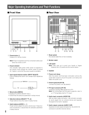
... been connected, remove the screw that is OFF. Major Operating Instructions and Their Functions Front View Rear View @1 @2 @3 @4 */165 4&-&$5 .&/6 4&-&$5 "6%*0 Video Monitor WV-LC1900 wr y q et u i o !0 q Power button Powers on or off , it lights in red while the power supply is supplied to the monitor. Note: Power is supplied from the connected cable even while the monitor is used to mount the power cord clamp and fasten the power cord. !2 Power input jack (AC IN) Connect the power cord (accessory). !3 PC input connector (PC IN) Accepts an analog RGB signal...
... been connected, remove the screw that is OFF. Major Operating Instructions and Their Functions Front View Rear View @1 @2 @3 @4 */165 4&-&$5 .&/6 4&-&$5 "6%*0 Video Monitor WV-LC1900 wr y q et u i o !0 q Power button Powers on or off , it lights in red while the power supply is supplied to the monitor. Note: Power is supplied from the connected cable even while the monitor is used to mount the power cord clamp and fasten the power cord. !2 Power input jack (AC IN) Connect the power cord (accessory). !3 PC input connector (PC IN) Accepts an analog RGB signal...
Operating Instructions
Page 9
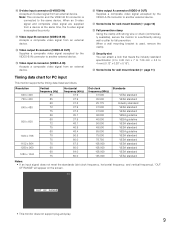
... vertical frequency), "OUT OF RANGE" will appear on the screen. • This monitor does not support plug-and-play. 9 When an S-video signal and composite video signal are supplied from a device at the same time, the S-video signal is used, remove the clamp. @3 Security slot You can attach a lock that meets the industry standard specification (3 to 3.26 mm x 7 to 7.26 mm x 3.5 to 4 mm) {0.12" x 0.28" x 0.15"}. @4 Screw holes for wall mount...
... vertical frequency), "OUT OF RANGE" will appear on the screen. • This monitor does not support plug-and-play. 9 When an S-video signal and composite video signal are supplied from a device at the same time, the S-video signal is used, remove the clamp. @3 Security slot You can attach a lock that meets the industry standard specification (3 to 3.26 mm x 7 to 7.26 mm x 3.5 to 4 mm) {0.12" x 0.28" x 0.15"}. @4 Screw holes for wall mount...
Operating Instructions
Page 10
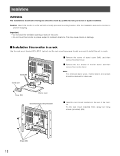
... be made by qualified service personnel or system installers. That may cause trouble or damage. Stand cover Screw (M4) Monitor stand Screw holes for future use. Fix the rack mount brackets firmly using four fixing screws (provided) (M4). Note: The removed stand cover, monitor stand and screws should be retained for rack mount bracket c Install the rack mount brackets on places subject to constant vibrations. Screw (M4) z Remove the screw of monitor stand, and then remove the monitor stand. Screws (M4) 10 Important...
... be made by qualified service personnel or system installers. That may cause trouble or damage. Stand cover Screw (M4) Monitor stand Screw holes for future use. Fix the rack mount brackets firmly using four fixing screws (provided) (M4). Note: The removed stand cover, monitor stand and screws should be retained for rack mount bracket c Install the rack mount brackets on places subject to constant vibrations. Screw (M4) z Remove the screw of monitor stand, and then remove the monitor stand. Screws (M4) 10 Important...
Operating Instructions
Page 11
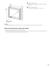
... the LCD panel. b Adjust the angle of the wall mount bracket and this unit. 11 The angle can be careful not to be mounted, and the pull-out strength should be more than 5 times the total weight of this unit firmly using eight mounting screws (locally procured). Fix this unit. Notes on the screw holes for wall mount bracket • Check how heavy the wall mount...
... the LCD panel. b Adjust the angle of the wall mount bracket and this unit. 11 The angle can be careful not to be mounted, and the pull-out strength should be more than 5 times the total weight of this unit firmly using eight mounting screws (locally procured). Fix this unit. Notes on the screw holes for wall mount bracket • Check how heavy the wall mount...

Operating Instructions
Page 12
Power cord (supplied) Digital disk recorder Audio output S-video output Video output 12 Connections Connection Example PC Monitor output (VGA) Other video monitors Video input Audio input * Be sure to secure the power cord with a power cord clamp.
Power cord (supplied) Digital disk recorder Audio output S-video output Video output 12 Connections Connection Example PC Monitor output (VGA) Other video monitors Video input Audio input * Be sure to secure the power cord with a power cord clamp.
Operating Instructions
Page 13
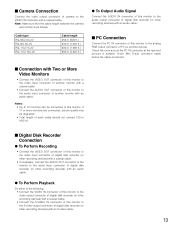
... analog RGB output connector of camera to the audio input connector of another monitor with a coaxial cable. • Connect the AUDIO OUT connector of this monitor to the S-video output connector of digital disk recorder (or other recording devices) with an S-video cable. 13 Connection with Two or More Video Monitors • Connect the VIDEO OUT connector of this monitor to the video input connector of another monitor with a coaxial cable. If 11 or more monitors are connected, picture quality may be connected...
... analog RGB output connector of camera to the audio input connector of another monitor with a coaxial cable. • Connect the AUDIO OUT connector of this monitor to the S-video output connector of digital disk recorder (or other recording devices) with an S-video cable. 13 Connection with Two or More Video Monitors • Connect the VIDEO OUT connector of this monitor to the video input connector of another monitor with a coaxial cable. If 11 or more monitors are connected, picture quality may be connected...
Operating Instructions
Page 14
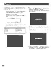
... operation, check the connections between monitors and external devices (cameras, digital disk recorders, etc.) (Refer to the diagram in green. 2. Press the power button. Every pressing this button can change input signals as follows. "NO SIGNAL" will be displayed until a cable is connected. • When the PC input signal is selected and picture display position is detected due to be displayed on the screen. VIDEO A Notes: • When no input signal is supplied to the monitor, "NO SIGNAL" will...
... operation, check the connections between monitors and external devices (cameras, digital disk recorders, etc.) (Refer to the diagram in green. 2. Press the power button. Every pressing this button can change input signals as follows. "NO SIGNAL" will be displayed until a cable is connected. • When the PC input signal is selected and picture display position is detected due to be displayed on the screen. VIDEO A Notes: • When no input signal is supplied to the monitor, "NO SIGNAL" will...
Operating Instructions
Page 15
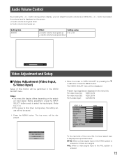
...input signal. Notes: • The menu title display differs depending on the screen. -: Audio volume level goes down. +: Audio volume level goes up . 0 to VIDEO ADJUST by pressing the C or D button. Audio Volume Control By pressing the + or - Move the cursor to + 40 -: Audio volume level goes down during picture display, you can adjust the audio volume level. button during setup, the setting values will be saved. 1. While the + or - For video input (A): VIDEO A IN For video input (B): VIDEO B IN For S-video input: S-VIDEO IN VIDEO B IN NTSC BRIGHTNESS 00 CONTRAST...
...input signal. Notes: • The menu title display differs depending on the screen. -: Audio volume level goes down. +: Audio volume level goes up . 0 to VIDEO ADJUST by pressing the C or D button. Audio Volume Control By pressing the + or - Move the cursor to + 40 -: Audio volume level goes down during picture display, you can adjust the audio volume level. button during setup, the setting values will be saved. 1. While the + or - For video input (A): VIDEO A IN For video input (B): VIDEO B IN For S-video input: S-VIDEO IN VIDEO B IN NTSC BRIGHTNESS 00 CONTRAST...
Operating Instructions
Page 16
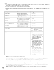
...) H-POSITION COLOR TEMP SCAN Effect +: Brightness level goes up. -: Brightness level goes down. +: Contrast level goes up. -: Contrast level goes down . +: Tint becomes more greenish. -: Tint becomes more , the monitor display returns to be 1:1, black strips are joined to EXIT by pressing the C or D button. Since the enlarged aspect ratio remains to the default status. 16 To reset the settings, move the cursor to each input signal. 4. The currently displayed input signal (VIDEO A, VIDEO...
...) H-POSITION COLOR TEMP SCAN Effect +: Brightness level goes up. -: Brightness level goes down. +: Contrast level goes up. -: Contrast level goes down . +: Tint becomes more greenish. -: Tint becomes more , the monitor display returns to be 1:1, black strips are joined to EXIT by pressing the C or D button. Since the enlarged aspect ratio remains to the default status. 16 To reset the settings, move the cursor to each input signal. 4. The currently displayed input signal (VIDEO A, VIDEO...
Operating Instructions
Page 17
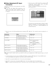
...-R USER COLOR-G USER COLOR-B Effect +: Brightness level goes up. -: Brightness level goes down. +: Contrast level goes up. -: Contrast level goes down. +: Red density level goes up. -: Red density level goes down. +: Green density level goes up. -: Green density level goes down. +: Blue density level goes up. -: Blue density level goes down. The top menu will be reset to NORMAL SETTINGS by pressing the C or D button. Press the MENU button. Select EXIT on the selected input signal. The currently displayed input signal (PC input) will be displayed. 6. The VIDEO ADJUST...
...-R USER COLOR-G USER COLOR-B Effect +: Brightness level goes up. -: Brightness level goes down. +: Contrast level goes up. -: Contrast level goes down. +: Red density level goes up. -: Red density level goes down. +: Green density level goes up. -: Green density level goes down. +: Blue density level goes up. -: Blue density level goes down. The top menu will be reset to NORMAL SETTINGS by pressing the C or D button. Press the MENU button. Select EXIT on the selected input signal. The currently displayed input signal (PC input) will be displayed. 6. The VIDEO ADJUST...
Operating Instructions
Page 18
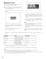
... 5. button. The top menu will be needed. 4. The monitor display return to p. 9.) • This monitor does not support plug-and-play. However, proper adjustment is decreased. The top menu will be displayed. The PC SETUP menu will be displayed. 6. Setting item H-POSITION V-POSITION CLOCK PHASE Effect +: Screen moves to the right. -: Screen moves to the timing data table ( Page 9), present signals are displayed in the format of [Resolution@Refresh rate (Vertical frequency)]. 3. Press the MENU button. Then, adjust the...
... 5. button. The top menu will be needed. 4. The monitor display return to p. 9.) • This monitor does not support plug-and-play. However, proper adjustment is decreased. The top menu will be displayed. The PC SETUP menu will be displayed. 6. Setting item H-POSITION V-POSITION CLOCK PHASE Effect +: Screen moves to the right. -: Screen moves to the timing data table ( Page 9), present signals are displayed in the format of [Resolution@Refresh rate (Vertical frequency)]. 3. Press the MENU button. Then, adjust the...
Operating Instructions
Page 19
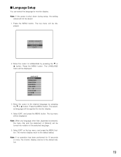
... MENU button. LANGUAGE ENGLISH FRANÇAIS DEUTSCH ESPAÑOL ITALIANO EXIT 3. Press the MENU button. VIDEO ADJUST PC SETUP LANGUAGE EXIT 2. The selected language will be applied for monitor display. 4. played. Note: If no operation has been performed for monitor display. Select EXIT, and press the MENU button. Note: If the power is selected, the menu title and the statement of the selected language. 5. Language Setup You can select the language...
... MENU button. LANGUAGE ENGLISH FRANÇAIS DEUTSCH ESPAÑOL ITALIANO EXIT 3. Press the MENU button. VIDEO ADJUST PC SETUP LANGUAGE EXIT 2. The selected language will be applied for monitor display. 4. played. Note: If no operation has been performed for monitor display. Select EXIT, and press the MENU button. Note: If the power is selected, the menu title and the statement of the selected language. 5. Language Setup You can select the language...
Operating Instructions
Page 20
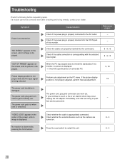
... the picture display position is displayed. Check whether the external devices such as the camera are turned on the PC menu. "NO SIGNAL" appears on the screen, and no picture is displayed. → Check the specifications of this monitor, no picture is displayed. Check if the cable connection is corresponding with the selected input signal. 8 - 9, 13 8 - 9, 13 "OUT OF RANGE" appears on the screen, and no image is not properly adjusted, perform manual adjustment. 18 The power cord, plug and connectors...
... the picture display position is displayed. Check whether the external devices such as the camera are turned on the PC menu. "NO SIGNAL" appears on the screen, and no picture is displayed. → Check the specifications of this monitor, no picture is displayed. Check if the cable connection is corresponding with the selected input signal. 8 - 9, 13 8 - 9, 13 "OUT OF RANGE" appears on the screen, and no image is not properly adjusted, perform manual adjustment. 18 The power cord, plug and connectors...
Operating Instructions
Page 21
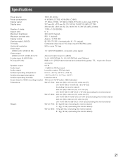
Specifications Power source: 120 V AC, 60 Hz Power consumption: 41 W (WV-LC1700), 43 W (WV-LC1900) Display panel: 17" (WV-LC1700), 19" (WV-LC1900) TFT LCD, built-in dual CCFT's Display area: 337 mm (H) x 270 mm (V) {13-1/4" (H) 10-5/8" (V)} (WV-LC1700) 376 mm (H) x 301 mm (V) {14-13/16" (H) 11-7/8" (V)} (WV-LC1900) Number of pixels: 1 280 x 1 024 (SXGA) Aspect ratio: 5 : 4 Maximum brightness: 300 cd/m2 (typical) Maximum contrast ratio: 800 : 1 (typical) Display colors: Approx. 16 700 000 Viewing angle...
Specifications Power source: 120 V AC, 60 Hz Power consumption: 41 W (WV-LC1700), 43 W (WV-LC1900) Display panel: 17" (WV-LC1700), 19" (WV-LC1900) TFT LCD, built-in dual CCFT's Display area: 337 mm (H) x 270 mm (V) {13-1/4" (H) 10-5/8" (V)} (WV-LC1700) 376 mm (H) x 301 mm (V) {14-13/16" (H) 11-7/8" (V)} (WV-LC1900) Number of pixels: 1 280 x 1 024 (SXGA) Aspect ratio: 5 : 4 Maximum brightness: 300 cd/m2 (typical) Maximum contrast ratio: 800 : 1 (typical) Display colors: Approx. 16 700 000 Viewing angle...


