
WJSX150 User Guide
Page 1
... when the auto login is set to ON. (Refer to check the version. (1) ADDENDUM FOR SYSTEM CONTROLLER WV-CU950/WV-CU650: MATRIX SWITCHER WJ-SX150 SERIES OPERATING PROCEDURES INSTALLATIONS AND CONNECTIONS ■ Basic System Connections • The connection details are the same as System Controller WV-CU360C/CJ. Terminal Mode No User Refer to the operating instructions of the terminal...
... when the auto login is set to ON. (Refer to check the version. (1) ADDENDUM FOR SYSTEM CONTROLLER WV-CU950/WV-CU650: MATRIX SWITCHER WJ-SX150 SERIES OPERATING PROCEDURES INSTALLATIONS AND CONNECTIONS ■ Basic System Connections • The connection details are the same as System Controller WV-CU360C/CJ. Terminal Mode No User Refer to the operating instructions of the terminal...

WJSX150 User Guide
Page 36
...Series), the following differences will occur. ■ Unavailable Functions through WJ-SX150A Connection The following functions are unavailable when the system controller (WV-CU950 or WV-CU650) is connected to recorders via the matrix switcher (WJ-SX150 Series). ● HD500 V-Multi LCD MENU HDD 204 HD500...514 HD200 Alm Search ■ Functions Only Available with WJ-HD300 Series The following functions are available only when the system controller (WV-CU950 or WV-CU650) is connected to WJHD300 Series via the matrix switcher (WJ-SX150 Series). ■ Functions Only Available with WJ-...
...Series), the following differences will occur. ■ Unavailable Functions through WJ-SX150A Connection The following functions are unavailable when the system controller (WV-CU950 or WV-CU650) is connected to recorders via the matrix switcher (WJ-SX150 Series). ● HD500 V-Multi LCD MENU HDD 204 HD500...514 HD200 Alm Search ■ Functions Only Available with WJ-HD300 Series The following functions are available only when the system controller (WV-CU950 or WV-CU650) is connected to WJHD300 Series via the matrix switcher (WJ-SX150 Series). ■ Functions Only Available with WJ-...

Operating Instructions
Page 1
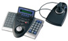
Before attempting to connect or operate this product, please read these instructions carefully and save this manual for future use. Operating Instructions System Controller WV-CU650 Model No.
Before attempting to connect or operate this product, please read these instructions carefully and save this manual for future use. Operating Instructions System Controller WV-CU650 Model No.
Operating Instructions
Page 2
... as a permanent record of your purchase to aid identification in which case the user will be of sufficient magnitude to constitute a risk of the unit. WV-CU650 Serial No. REFER SERVICING TO QUALIFIED SERVICE PERSONNEL. FCC Caution: To assure continued compliance, (example use only shielded interface cables when connecting to operate this...
... as a permanent record of your purchase to aid identification in which case the user will be of sufficient magnitude to constitute a risk of the unit. WV-CU650 Serial No. REFER SERVICING TO QUALIFIED SERVICE PERSONNEL. FCC Caution: To assure continued compliance, (example use only shielded interface cables when connecting to operate this...

Operating Instructions
Page 5
... ID's and passwords Operation authority (=user level) is assignable to prevent inappropriate operations. 5 You can control the camera zooming by moving the zoom wheel controller of cameras and other system units installed in a surveillance system. PREFACE This product, System Controller WV-CU650, is separated from the main unit. The function assignment is assignable to each user ID. These...
... ID's and passwords Operation authority (=user level) is assignable to prevent inappropriate operations. 5 You can control the camera zooming by moving the zoom wheel controller of cameras and other system units installed in a surveillance system. PREFACE This product, System Controller WV-CU650, is separated from the main unit. The function assignment is assignable to each user ID. These...
Operating Instructions
Page 7
... are described in the following convention when describing the use and operation of this system controller. Addendum for WV-CU650 and WJ-SX150 Series 7 System controller: Panasonic System Controller WV-CU650 Caution(s): Caution statements identify conditions or practices that could result in this product or injury. NOTIFICATION ABOUT SYSTEM UNITS Matrix Switcher WJ-SX150 Series Ver. 2.03 or later supports this unit. The...
... are described in the following convention when describing the use and operation of this system controller. Addendum for WV-CU650 and WJ-SX150 Series 7 System controller: Panasonic System Controller WV-CU650 Caution(s): Caution statements identify conditions or practices that could result in this product or injury. NOTIFICATION ABOUT SYSTEM UNITS Matrix Switcher WJ-SX150 Series Ver. 2.03 or later supports this unit. The...

Operating Instructions
Page 8
...SUSPEND" indicator lights up when an alarm is activated. MAJOR OPERATING CONTROLS AND THEIR FUNCTIONS ■ Main Unit ● Front View #9 $0#8 $1 $2 $3 $4 r qwe t !1 !3 !4 !7 !5 !6 !8 @0 !9 @3 @2 @1 !2 o i u !0 y WV-CU650 ALARM ACK ALM RESET ALM SUSPEND OSD ALM ALL RESET ALM RECALL... CAM FUNC SEQ PAUSE SYS FUNC TOUR SEQ MON LOCK SEQ STOP GROUP SEQ MULTI SCREEN EL-ZOOM LOGOUT GO TO LAST AUX1 ON AUX2 ON MARK ADJUST MENU F1 F2 F3 F4 EXIT ENTER SYSTEM CONTROLLER SHIFT ALM...
...SUSPEND" indicator lights up when an alarm is activated. MAJOR OPERATING CONTROLS AND THEIR FUNCTIONS ■ Main Unit ● Front View #9 $0#8 $1 $2 $3 $4 r qwe t !1 !3 !4 !7 !5 !6 !8 @0 !9 @3 @2 @1 !2 o i u !0 y WV-CU650 ALARM ACK ALM RESET ALM SUSPEND OSD ALM ALL RESET ALM RECALL... CAM FUNC SEQ PAUSE SYS FUNC TOUR SEQ MON LOCK SEQ STOP GROUP SEQ MULTI SCREEN EL-ZOOM LOGOUT GO TO LAST AUX1 ON AUX2 ON MARK ADJUST MENU F1 F2 F3 F4 EXIT ENTER SYSTEM CONTROLLER SHIFT ALM...

Operating Instructions
Page 16
...9 10/0 11 12 13 14 15 16 Digital Disk Recorder WJ-HD300 Series To PS·Data ports Used when adding other WV-CU650 system controllers (Available up to p. 18 for details on settings. 78 78 78 78 23 23 23 23 INSTALLATIONS AND CONNECTIONS WARNING The ... service personnel or system installers. ■ Basic System Connections The following is an example in which a recorder and data multiplex units are connected. DC9V IN Fixed Line termination: ON PS·Data Mode OFF ON MODE 901 CONTROLLER No.: 1 Refer to 3) Modular cable (supplied) System Controller WV-CU650 (Main unit)...
...9 10/0 11 12 13 14 15 16 Digital Disk Recorder WJ-HD300 Series To PS·Data ports Used when adding other WV-CU650 system controllers (Available up to p. 18 for details on settings. 78 78 78 78 23 23 23 23 INSTALLATIONS AND CONNECTIONS WARNING The ... service personnel or system installers. ■ Basic System Connections The following is an example in which a recorder and data multiplex units are connected. DC9V IN Fixed Line termination: ON PS·Data Mode OFF ON MODE 901 CONTROLLER No.: 1 Refer to 3) Modular cable (supplied) System Controller WV-CU650 (Main unit)...

Operating Instructions
Page 18
... to log into the system by moving the CONTROLLER NO. Perform WV-CU650 setups after entering the administrator password. Notes: • "0" and "9" are connectable in the system. Set the MODE switches. You will perform this setting when using only one system controller Maintain the switch setting as follows. 1. Addendum for controller numbers. • One of the system controller at the rear...
... to log into the system by moving the CONTROLLER NO. Perform WV-CU650 setups after entering the administrator password. Notes: • "0" and "9" are connectable in the system. Set the MODE switches. You will perform this setting when using only one system controller Maintain the switch setting as follows. 1. Addendum for controller numbers. • One of the system controller at the rear...

Operating Instructions
Page 25
... source system controller. switch is set to 1.) to p. 20 PS·Data Communication Setting.) • This function is correct, the LCD display of source system controller becomes as follows. If the password entered is available only among WV-CU650 System Controllers. Switch Setting.) Note: Set a unique number for each system controller. Login is "650". 9. The LCD display of source system controller becomes...
... source system controller. switch is set to 1.) to p. 20 PS·Data Communication Setting.) • This function is correct, the LCD display of source system controller becomes as follows. If the password entered is available only among WV-CU650 System Controllers. Switch Setting.) Note: Set a unique number for each system controller. Login is "650". 9. The LCD display of source system controller becomes...


