

WVCW964 User Guide
Page 1
Before attempting to connect or operate this product, please read these instructions carefully and save this manual for future use. Color CCTV Camera Operating Instructions WV-CW964 Model No.
Before attempting to connect or operate this product, please read these instructions carefully and save this manual for future use. Color CCTV Camera Operating Instructions WV-CW964 Model No.
WVCW964 User Guide
Page 4
... CLAIM OR ACTION FOR DAMAGES, BROUGHT BY ANY PERSON OR ORGANIZATION BEING PHOTOGENIC SUBJECT, DUE TO VIOLATION OF PRIVACY WITH THE RESULT OF THAT SURVEILLANCE-CAMERA's PICTURE, INCLUDING SAVED DATA, FOR SOME REASON, BECOMES PUBLIC OR IS USED FOR THE PURPOSE OTHER THAN SURVEILLANCE. (7) ANY PROBLEM, CONSEQUENTIAL INCONVENIENCE, ANY LOSS OR...
... CLAIM OR ACTION FOR DAMAGES, BROUGHT BY ANY PERSON OR ORGANIZATION BEING PHOTOGENIC SUBJECT, DUE TO VIOLATION OF PRIVACY WITH THE RESULT OF THAT SURVEILLANCE-CAMERA's PICTURE, INCLUDING SAVED DATA, FOR SOME REASON, BECOMES PUBLIC OR IS USED FOR THE PURPOSE OTHER THAN SURVEILLANCE. (7) ANY PROBLEM, CONSEQUENTIAL INCONVENIENCE, ANY LOSS OR...
WVCW964 User Guide
Page 5
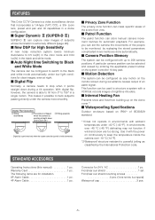
...configured with up on the dome cover.*1 ■ Waterproofing Specifications Outdoor enclosure based on IP66*2 of IEC60529 standard. *1 Does not operate in environments with the power on continuously to keep the temperature inside the camera over -40 °C {-40 °F} defrosting may not function... Connector for installation. 8P Alarm Cable 1 pc. 4P Alarm Cable 1 pc. This makes it with ambient temperatures under the camera more smoothly. A particular camera position can mask specific areas of the scene from 0° to track subjects passing directly under -40 °C {-40 &#...
...configured with up on the dome cover.*1 ■ Waterproofing Specifications Outdoor enclosure based on IP66*2 of IEC60529 standard. *1 Does not operate in environments with the power on continuously to keep the temperature inside the camera over -40 °C {-40 °F} defrosting may not function... Connector for installation. 8P Alarm Cable 1 pc. 4P Alarm Cable 1 pc. This makes it with ambient temperatures under the camera more smoothly. A particular camera position can mask specific areas of the scene from 0° to track subjects passing directly under -40 °C {-40 &#...
WVCW964 User Guide
Page 6
... this product. -6- Shock absorbers should be exposed to condensation, remove the dome cover and wipe all moist surfaces with time. Otherwise the camera could be any damage, whether direct or indirect, caused by switching the air conditioner on the load bearing capacity of CRT. 7. Afterwards,...places as the lens-drive motors, cooling fan motor and slip-rings inside . There are no user-serviceable parts inside the camera are subject to the camera. 6. Do not use , never aim it happens frequently, check if there would be damaged by improper handling or storage....
... this product. -6- Shock absorbers should be exposed to condensation, remove the dome cover and wipe all moist surfaces with time. Otherwise the camera could be any damage, whether direct or indirect, caused by switching the air conditioner on the load bearing capacity of CRT. 7. Afterwards,...places as the lens-drive motors, cooling fan motor and slip-rings inside . There are no user-serviceable parts inside the camera are subject to the camera. 6. Do not use , never aim it happens frequently, check if there would be damaged by improper handling or storage....
WVCW964 User Guide
Page 7
... a soft cloth. Contact the nearest service dealer about replacement and maintenance of an image may damage the camera or cause leaks. ■ This camera is not a malfunction. ■ Do not aim the camera at a strong light source. Gently wipe it with a weak solution of the dome cover and is... Long operation under high temperatures and high humidity can cause deterioration of the CCD internal color filters, and discoloration of the camera has become extremely hot. Use lens cleaning paper (like the type available for a long period can cause components to deteriorate and shorten...
... a soft cloth. Contact the nearest service dealer about replacement and maintenance of an image may damage the camera or cause leaks. ■ This camera is not a malfunction. ■ Do not aim the camera at a strong light source. Gently wipe it with a weak solution of the dome cover and is... Long operation under high temperatures and high humidity can cause deterioration of the CCD internal color filters, and discoloration of the camera has become extremely hot. Use lens cleaning paper (like the type available for a long period can cause components to deteriorate and shorten...

WVCW964 User Guide
Page 8
...camera, so you should contact a qualified service person or system installer as soon as possible. ■ Combining devices There is a limit to the system controller etc. Reset operation the same initialization routine that can be downloaded to other reason continues for more information, see the "Panasonic...error and failure of the uploading process. ■ Self-diagnosing Function If abnormal operation due to the camera. For more than 30 seconds, the camera will automatically reset itself and restore normal operation. or uploading downloaded data to external noise or some other...
...camera, so you should contact a qualified service person or system installer as soon as possible. ■ Combining devices There is a limit to the system controller etc. Reset operation the same initialization routine that can be downloaded to other reason continues for more information, see the "Panasonic...error and failure of the uploading process. ■ Self-diagnosing Function If abnormal operation due to the camera. For more than 30 seconds, the camera will automatically reset itself and restore normal operation. or uploading downloaded data to external noise or some other...
WVCW964 User Guide
Page 9
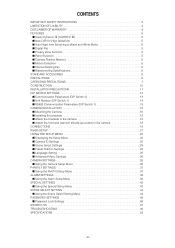
... Auto Night time Switching to Black and White Mode 5 ■ Digital Flip 5 ■ Privacy Zone Function 5 ■ Patrol Function 5 ■ Camera Position Memory 5 ■ Motion Detection 5 ■ Internal Heating Fan 5 ■ Waterproofing Specifications 5 STANDARD ACCESORIES 5 PRECAUTIONS 6 OPERATING PRECAUTIONS 7 CONSTRUCTION... 23 ■ Preset Position Settings 23 ■ Language Setting 25 ■ Advanced Menu Settings 25 CAMERA SETTINGS 26 ■ Using the Camera Setup Menu 26 PAN/TILT SETTINGS 31 ■ Using the Pan/Tilt Setup Menu 31 ALARM SETTINGS ...
... Auto Night time Switching to Black and White Mode 5 ■ Digital Flip 5 ■ Privacy Zone Function 5 ■ Patrol Function 5 ■ Camera Position Memory 5 ■ Motion Detection 5 ■ Internal Heating Fan 5 ■ Waterproofing Specifications 5 STANDARD ACCESORIES 5 PRECAUTIONS 6 OPERATING PRECAUTIONS 7 CONSTRUCTION... 23 ■ Preset Position Settings 23 ■ Language Setting 25 ■ Advanced Menu Settings 25 CAMERA SETTINGS 26 ■ Using the Camera Setup Menu 26 PAN/TILT SETTINGS 31 ■ Using the Pan/Tilt Setup Menu 31 ALARM SETTINGS ...

WVCW964 User Guide
Page 10
...of its service life. A dirty slip ring can cause deterioration of picture quality during panning and generation of noise. CONSTRUCTION Camera Safety Wire Alarm Input Connector Alarm Output Connector Video Output Connector Data Port Power Cord for transmission of electrical power and signals.... Ensuring Trouble-free Operation • This camera uses a "slip ring" for Heater Power Connector Attachment Pipe Upper Base Rear sun shield (provided) Front sun shield (provided) Sun...
...of its service life. A dirty slip ring can cause deterioration of picture quality during panning and generation of noise. CONSTRUCTION Camera Safety Wire Alarm Input Connector Alarm Output Connector Video Output Connector Data Port Power Cord for transmission of electrical power and signals.... Ensuring Trouble-free Operation • This camera uses a "slip ring" for Heater Power Connector Attachment Pipe Upper Base Rear sun shield (provided) Front sun shield (provided) Sun...

WVCW964 User Guide
Page 11
... ■ Never install or use the camera in the following locations. • Near a swimming pool or other areas where chemicals are used in the camera, Panasonic holds absolutely no responsibility for mounting the ceiling mount Attachment Pipe to the camera so it can be sure to check ...the DIP switch settings before setting up the camera for a configuration where the camera's RS485 data port is used for camera control (pan, ...
... ■ Never install or use the camera in the following locations. • Near a swimming pool or other areas where chemicals are used in the camera, Panasonic holds absolutely no responsibility for mounting the ceiling mount Attachment Pipe to the camera so it can be sure to check ...the DIP switch settings before setting up the camera for a configuration where the camera's RS485 data port is used for camera control (pan, ...
WVCW964 User Guide
Page 12
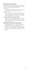
...quality of the picture. ■ Important hints to help with the installation • A self-cleaning function is activated (PAN/TILT/ ZOOM/FOCUS) when the camera is turned on. • There is installed, may collect on the dome cover and block some of the picture. (The amount of snow that collects...wiper. ■ About effects on the quality and amount of the snow.) (3) Effects of devices that can be put together in one configuration. If the camera is installed in the following conditions image quality may deteriorate or the image may be invisible. (1) In the rain The picture may be hard to...
...quality of the picture. ■ Important hints to help with the installation • A self-cleaning function is activated (PAN/TILT/ ZOOM/FOCUS) when the camera is turned on. • There is installed, may collect on the dome cover and block some of the picture. (The amount of snow that collects...wiper. ■ About effects on the quality and amount of the snow.) (3) Effects of devices that can be put together in one configuration. If the camera is installed in the following conditions image quality may deteriorate or the image may be invisible. (1) In the rain The picture may be hard to...
WVCW964 User Guide
Page 13
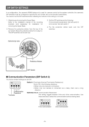
... ceiling or on a wall. 1. Set the DIP switches as the following situations. • When only one camera is connected. • When only one camera is used . ON ON 1234 4-line Communication 1234 2-line Communication -13- ON 1234 Communication Parameters Terminator Switch... (Internal Termination Resistance) Set to select the communication protocol being used for camera control by the system controller, the camera's DIP switches must be set the DIP switches before installing the camera in the following : Communication parameters: Set with switch 2 Unit number: ...
... ceiling or on a wall. 1. Set the DIP switches as the following situations. • When only one camera is connected. • When only one camera is used . ON ON 1234 4-line Communication 1234 2-line Communication -13- ON 1234 Communication Parameters Terminator Switch... (Internal Termination Resistance) Set to select the communication protocol being used for camera control by the system controller, the camera's DIP switches must be set the DIP switches before installing the camera in the following : Communication parameters: Set with switch 2 Unit number: ...
WVCW964 User Guide
Page 15
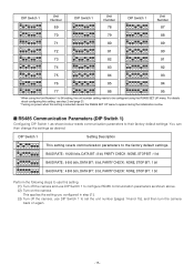
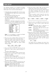
...Switch 1 as shown below resets communication parameters to their factory default settings. This applies the setting you configured in step (1). (3) Turn off the camera and use DIP Switch 1 to configure RS485 communication parameters as desired. For details about configuring this setting, see step 2 and page 21. ...* Turning on power when this setting. (1) Turn off the camera, use DIP Switch 1 to set the unit number (pages 14 and 15), and then turn the camera back on the camera. DIP Switch 1 ON 12345678 ON 12345678 ON 12345678 ON 12345678 Setting Description This ...
...Switch 1 as shown below resets communication parameters to their factory default settings. This applies the setting you configured in step (1). (3) Turn off the camera and use DIP Switch 1 to configure RS485 communication parameters as desired. For details about configuring this setting, see step 2 and page 21. ...* Turning on power when this setting. (1) Turn off the camera, use DIP Switch 1 to set the unit number (pages 14 and 15), and then turn the camera back on the camera. DIP Switch 1 ON 12345678 ON 12345678 ON 12345678 ON 12345678 Setting Description This ...

WVCW964 User Guide
Page 16
.... * Special screw (mounting screw): Use a hexagon wrench for fixing on a ceiling with a locally procured bracket. Disassembling the Camera (1) Remove the upper base from the camera by loosening 4 screws. * Special screw (mounting screw): Use a hexagon wrench for filling gaps and holes with waterproof material. ...the place you are removed need to the instructions included with the bracket for the hexagon button screw (M6). (2) To prevent the camera from falling, use a mounting a bracket to which a safety wire can be attached. (3) Installation Surface x4 Caution: Consult an expert...
.... * Special screw (mounting screw): Use a hexagon wrench for fixing on a ceiling with a locally procured bracket. Disassembling the Camera (1) Remove the upper base from the camera by loosening 4 screws. * Special screw (mounting screw): Use a hexagon wrench for filling gaps and holes with waterproof material. ...the place you are removed need to the instructions included with the bracket for the hexagon button screw (M6). (2) To prevent the camera from falling, use a mounting a bracket to which a safety wire can be attached. (3) Installation Surface x4 Caution: Consult an expert...
WVCW964 User Guide
Page 17
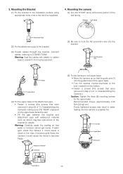
...prevent it from the bottom. • Fasten 3 screws (the screws that were removed in step (2) of "2. Also, if moisture gets inside the camera it could cause the dome to the end, viewed from being exposed. (2) Be sure to CONNECTIONS. Caution: Tighten the three (3) mounting screws for ... Upper Base Enclosure Upper Base -17- Mounting the Bracket (1) Fix the bracket to the bracket. (3) Thread cables through the bracket. 3. Mounting the camera (1) Aim the "START" arrow at the bent portion of the bracket for the upper base. Bending Leaf Spring S TA R T Attachment Pipe (2)...
...prevent it from the bottom. • Fasten 3 screws (the screws that were removed in step (2) of "2. Also, if moisture gets inside the camera it could cause the dome to the end, viewed from being exposed. (2) Be sure to CONNECTIONS. Caution: Tighten the three (3) mounting screws for ... Upper Base Enclosure Upper Base -17- Mounting the Bracket (1) Fix the bracket to the bracket. (3) Thread cables through the bracket. 3. Mounting the camera (1) Aim the "START" arrow at the bent portion of the bracket for the upper base. Bending Leaf Spring S TA R T Attachment Pipe (2)...
WVCW964 User Guide
Page 18
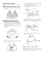
... by the indentations on the sun shield and then turn them . Align with the brackets. ■ Attach the brackets to the camera 1. A wire is designed to allow the camera to hang from both sides to separate them to the "LOCK" arrow (˚) until they click. Hold the front and rear .... ■ Installing the brackets Refer to the installation guides provided with this arrow Wire 5. Put the waterproof caps (provided) onto the tops of the camera to the wire. -18- Before clamping the sun shield, close the front and rear sun shields (first latch the hook on the wire side, and...
... by the indentations on the sun shield and then turn them . Align with the brackets. ■ Attach the brackets to the camera 1. A wire is designed to allow the camera to hang from both sides to separate them to the "LOCK" arrow (˚) until they click. Hold the front and rear .... ■ Installing the brackets Refer to the installation guides provided with this arrow Wire 5. Put the waterproof caps (provided) onto the tops of the camera to the wire. -18- Before clamping the sun shield, close the front and rear sun shields (first latch the hook on the wire side, and...
WVCW964 User Guide
Page 19
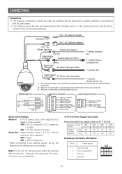
...so can cause pan, tilt, zoom, or focus to go out of position. • 24 V AC Power Supply Connection Recommended wire gauge sizes for camera 24 V AC RS485 Data Port Twisted Pair Cable*1 (RJ-12) Video Output Connector Coaxial Cable (5C-2V)*2 (BNC) Alarm Input Connector 8P Alarm... Copper wire size #24 #22 #20 #18 (AWG) (0.22mm2) (0.33mm2) (0.52mm2) (0.83mm2) Length (m) 20 of at lease 0.2 mA required. To VIDEO IN port (CAMERA IN) To sensor, etc. Power source 1 24 V AC LIVE 2 24 V AC NEUTRAL 3 Ground 4 Not use shielded low-impedance cable with all local codes. •...
...so can cause pan, tilt, zoom, or focus to go out of position. • 24 V AC Power Supply Connection Recommended wire gauge sizes for camera 24 V AC RS485 Data Port Twisted Pair Cable*1 (RJ-12) Video Output Connector Coaxial Cable (5C-2V)*2 (BNC) Alarm Input Connector 8P Alarm... Copper wire size #24 #22 #20 #18 (AWG) (0.22mm2) (0.33mm2) (0.52mm2) (0.83mm2) Length (m) 20 of at lease 0.2 mA required. To VIDEO IN port (CAMERA IN) To sensor, etc. Power source 1 24 V AC LIVE 2 24 V AC NEUTRAL 3 Ground 4 Not use shielded low-impedance cable with all local codes. •...

WVCW964 User Guide
Page 20
... contacts, push them into the proper holes in place. Do not shrink the cable-entry seal until they snap in the accessory connector of this camera until ascertaining that the unit is a one-time procedure. CCoonntatcatct AApppproroxx. . 33 mmmm{{00.1.1"}"} UUpp A Insert WWiriere IInnsseertrtththeewwireireunutniltAil Apopsoitisointion aannddcclalammppthtehecocnotanctatsc. Use MOLEX band tool part...
... contacts, push them into the proper holes in place. Do not shrink the cable-entry seal until they snap in the accessory connector of this camera until ascertaining that the unit is a one-time procedure. CCoonntatcatct AApppproroxx. . 33 mmmm{{00.1.1"}"} UUpp A Insert WWiriere IInnsseertrtththeewwireireunutniltAil Apopsoitisointion aannddcclalammppthtehecocnotanctatsc. Use MOLEX band tool part...
WVCW964 User Guide
Page 21
...tilt the joystick left or right to 96). ** RS485 SETUP ** UNIT NUMBER 1 SUB ADDRESS ----- The wait time is the time that the camera should wait before resending data when no receive acknowledgement (ACK) is returned after data is sent. Tilting the joystick cycles through the baud rate (...default setting. 10. OFF ↔ 100MS ↔ 200MS ↔ 400MS ↔ 1000MS 9. The delay time is the time is the time the camera should wait before sending a receive acknowledge (ACK). Move the cursor to ALARM DATA, and then tilt the joystick left or right to select a parity...
...tilt the joystick left or right to 96). ** RS485 SETUP ** UNIT NUMBER 1 SUB ADDRESS ----- The wait time is the time that the camera should wait before resending data when no receive acknowledgement (ACK) is returned after data is sent. Tilting the joystick cycles through the baud rate (...default setting. 10. OFF ↔ 100MS ↔ 200MS ↔ 400MS ↔ 1000MS 9. The delay time is the time is the time the camera should wait before sending a receive acknowledge (ACK). Move the cursor to ALARM DATA, and then tilt the joystick left or right to select a parity...

WVCW964 User Guide
Page 22
...press the CAM (SET) button. DOOR Repeat step 3 as many times as necessary to input all previously input characters Move the cursor to input the camera ID. 1. Finally, use step 3 above to SPACE, and then press the CAM (SET) button. This section explains how to display the setup ...default setting is a series of alphanumeric characters that it contains. ■ Displaying the Setup Menu ● When using the WV-CU650 (1) Select the camera (this camera), and the monitor where displays the setup menu. (2) Press the MENU button to display LCD MENU CAM 101. (3) Press the ENTER button or CAM...
...press the CAM (SET) button. DOOR Repeat step 3 as many times as necessary to input all previously input characters Move the cursor to input the camera ID. 1. Finally, use step 3 above to SPACE, and then press the CAM (SET) button. This section explains how to display the setup ...default setting is a series of alphanumeric characters that it contains. ■ Displaying the Setup Menu ● When using the WV-CU650 (1) Select the camera (this camera), and the monitor where displays the setup menu. (2) Press the MENU button to display LCD MENU CAM 101. (3) Press the ENTER button or CAM...
WVCW964 User Guide
Page 23
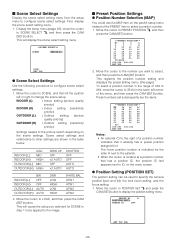
... ID text appears next to ID: on the pan/tilt setup menu instead of the menu, and then press the CAM (SET) button. INDOOR (L) INDOOR (H) OUTDOOR (L) OUTDOOR (H) AGC MID HIGH MID HIGH SENS UP OFF ×2 AUTO OFF ×2 AUTO SHUTTER OFF OFF AUTO AUTO INDOOR (L) INDOOR... a position number that it already has a preset position assigned to SCENE SELECT O, and then press the CAM (SET) button. Move the cursor to specify the camera position (pan and tilt), the lens zoom setting, and the focus setting. 1. Move the cursor to change the scene setup. Move the cursor to select...
... ID text appears next to ID: on the pan/tilt setup menu instead of the menu, and then press the CAM (SET) button. INDOOR (L) INDOOR (H) OUTDOOR (L) OUTDOOR (H) AGC MID HIGH MID HIGH SENS UP OFF ×2 AUTO OFF ×2 AUTO SHUTTER OFF OFF AUTO AUTO INDOOR (L) INDOOR... a position number that it already has a preset position assigned to SCENE SELECT O, and then press the CAM (SET) button. Move the cursor to specify the camera position (pan and tilt), the lens zoom setting, and the focus setting. 1. Move the cursor to change the scene setup. Move the cursor to select...


