
Owner's Manual
Page 1
...-CHANNEL RECEIVER VSX-917V Register your product at www.pioneerelectronics.com (US) www.pioneerelectronics.ca (Canada) • Protect your new investment The details of your purchase will be on file for reference in the event of an insurance claim such as loss or theft. • Receive free ...tips, updates and service bulletins on your new product • Improve product development Your input helps us continue to design products that meet your needs. • Receive a free Pioneer newsletter Registered customers can opt in to...
...-CHANNEL RECEIVER VSX-917V Register your product at www.pioneerelectronics.com (US) www.pioneerelectronics.ca (Canada) • Protect your new investment The details of your purchase will be on file for reference in the event of an insurance claim such as loss or theft. • Receive free ...tips, updates and service bulletins on your new product • Improve product development Your input helps us continue to design products that meet your needs. • Receive a free Pioneer newsletter Registered customers can opt in to...

Owner's Manual
Page 2
.... To prevent electromagnetic interference with electric appliances such as radios and televisions, use , the plug must accept any interference received, including interference that may not cause harmful interference, and (2) this unit should be disconnected by removing the mains plug ...Classe B est conforme à la norme NMB-003 du Canada. Product Name: AUDIO/VIDEO MULTI-CHANNEL RECEIVER Model Number: VSX-917V-K, VSX-917V-S Responsible Party Name: PIONEER ELECTRONICS SERVICE INC. PLEASE WRITE THIS SERIAL NUMBER ON YOUR ENCLOSED WARRANTY CARD AND KEEP IN A SECURE...
.... To prevent electromagnetic interference with electric appliances such as radios and televisions, use , the plug must accept any interference received, including interference that may not cause harmful interference, and (2) this unit should be disconnected by removing the mains plug ...Classe B est conforme à la norme NMB-003 du Canada. Product Name: AUDIO/VIDEO MULTI-CHANNEL RECEIVER Model Number: VSX-917V-K, VSX-917V-S Responsible Party Name: PIONEER ELECTRONICS SERVICE INC. PLEASE WRITE THIS SERIAL NUMBER ON YOUR ENCLOSED WARRANTY CARD AND KEEP IN A SECURE...

Owner's Manual
Page 4
... start Checking what's in the box 6 Loading the batteries 6 Installing the receiver 6 Ventilation 6 02 5 minute guide Introduction to home theater 7 Listening to Surround Sound 7 Automatically setting up for buying this Pioneer product. Thank you will know how to operate your system Auto playback 28 ... 11 About the video converter 12 Connecting a DVD player and TV 13 Connecting the multichannel analog outputs 14 Connecting a satellite receiver or other digital set-top box 14 Connecting other audio components 15 About the WMA9 Pro decoder 15 Connecting other sources 33...
... start Checking what's in the box 6 Loading the batteries 6 Installing the receiver 6 Ventilation 6 02 5 minute guide Introduction to home theater 7 Listening to Surround Sound 7 Automatically setting up for buying this Pioneer product. Thank you will know how to operate your system Auto playback 28 ... 11 About the video converter 12 Connecting a DVD player and TV 13 Connecting the multichannel analog outputs 14 Connecting a satellite receiver or other digital set-top box 14 Connecting other audio components 15 About the WMA9 Pro decoder 15 Connecting other sources 33...
Owner's Manual
Page 5
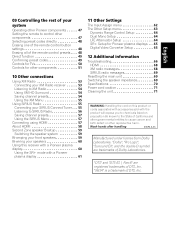
... Confirming preset codes 49 Controls for TVs 50 Controls for other components 51 10 Other connections Using XM Radio 53 Connecting your XM Radio receiver 53 Listening to XM Radio 54 Using XM HD Surround 54 Saving channel presets 54 Using the XM Menu 55 Using SIRIUS Radio 55 ... setup 59 Switching the speaker system 59 Bi-amping your front speakers 59 Bi-wiring your speakers 60 Using this receiver with a Pioneer plasma display 60 Using the SR+ mode with a Pioneer plasma display 61 11 Other Settings The Input Assign menu 62 The Other Setup menu 63 Dynamic Range Control Setup 64...
... Confirming preset codes 49 Controls for TVs 50 Controls for other components 51 10 Other connections Using XM Radio 53 Connecting your XM Radio receiver 53 Listening to XM Radio 54 Using XM HD Surround 54 Saving channel presets 54 Using the XM Menu 55 Using SIRIUS Radio 55 ... setup 59 Switching the speaker system 59 Bi-amping your front speakers 59 Bi-wiring your speakers 60 Using this receiver with a Pioneer plasma display 60 Using the SR+ mode with a Pioneer plasma display 61 11 Other Settings The Input Assign menu 62 The Other Setup menu 63 Dynamic Range Control Setup 64...
Owner's Manual
Page 6
...AA size IEC R6) x2 • AM loop antenna • FM wire antenna • These operating instructions Loading the batteries Installing the receiver When installing this unit, make sure to leave space around the unit for ventilation and to the marks in the battery case. • ... other movement - Observe the following places: - Don't install it on a level and stable surface. in places that apply in your country or area. Receiver 20 cm (8 inches) Slot and openings in places that gives off a magnetic field). on thick carpet or a bed. 6 En near a cassette deck...
...AA size IEC R6) x2 • AM loop antenna • FM wire antenna • These operating instructions Loading the batteries Installing the receiver When installing this unit, make sure to leave space around the unit for ventilation and to the marks in the battery case. • ... other movement - Observe the following places: - Don't install it on a level and stable surface. in places that apply in your country or area. Receiver 20 cm (8 inches) Slot and openings in places that gives off a magnetic field). on thick carpet or a bed. 6 En near a cassette deck...

Owner's Manual
Page 7
... player's manual for the best surround sound effect. Listening to Surround Sound With the following quick setup guide, you can simply leave the receiver in the default settings. • Be sure to complete all . Place your speakers as shown below for optimal surround sound. Check the... manual that DVD is showing in the receiver's display. See Connecting a DVD player and TV on page 19. 5 minute guide 02 English Deutsch Français Italiano Nederlands Español Chapter...
... player's manual for the best surround sound effect. Listening to Surround Sound With the following quick setup guide, you can simply leave the receiver in the default settings. • Be sure to complete all . Place your speakers as shown below for optimal surround sound. Check the... manual that DVD is showing in the receiver's display. See Connecting a DVD player and TV on page 19. 5 minute guide 02 English Deutsch Français Italiano Nederlands Español Chapter...

Owner's Manual
Page 8
...EDIT RETURN TUNE GUIDE CATEGORY TV CONTROL TV VOL INPUT SELECT TV CH VOL DTVON/OFF REC DTVINFO 1 Switch on the receiver and your system, the receiver uses the information from the System Setup menu then press ENTER. Note 1 • The screensaver automatically starts after pressing ... test tones to optimize the speaker settings and equalization for system setup. 2 If you have connected using a table or a chair. 3 Press RECEIVER on your listening area, taking into account ambient noise, speaker size and distance, and tests for both channel delay and channel level. Use component,...
...EDIT RETURN TUNE GUIDE CATEGORY TV CONTROL TV VOL INPUT SELECT TV CH VOL DTVON/OFF REC DTVINFO 1 Switch on the receiver and your system, the receiver uses the information from the System Setup menu then press ENTER. Note 1 • The screensaver automatically starts after pressing ... test tones to optimize the speaker settings and equalization for system setup. 2 If you have connected using a table or a chair. 3 Press RECEIVER on your listening area, taking into account ambient noise, speaker size and distance, and tests for both channel delay and channel level. Use component,...

Owner's Manual
Page 9
...can correct the setting manually using a subwoofer, it is automatically detected every time you switch on -screen while the receiver outputs more test tones to determine the optimum receiver settings for channel level, speaker distance, and Acoustic Calibration EQ. 2.Auto MCACC Now Analyzing Surround Analyzing Speaker System [ ... on the front panel will start again from the Analyzed Data Check screen: Note 1 • Depending on -screen while the receiver outputs test tones to determine the speakers present in the right side column, there may take 3 to view the settings by selecting...
...can correct the setting manually using a subwoofer, it is automatically detected every time you switch on -screen while the receiver outputs more test tones to determine the optimum receiver settings for channel level, speaker distance, and Acoustic Calibration EQ. 2.Auto MCACC Now Analyzing Surround Analyzing Speaker System [ ... on the front panel will start again from the Analyzed Data Check screen: Note 1 • Depending on -screen while the receiver outputs test tones to determine the speakers present in the right side column, there may take 3 to view the settings by selecting...
Owner's Manual
Page 10
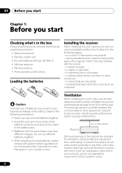
... the walls, obstacles blocking the speakers from the listening position (see page 42 for more on phase correction. Other problems when using Phase Control This receiver's Phase Control feature uses phase correction measures to switch on this ) Press RETURN after you have finished checking each screen. P Front speaker H A S E C O N T R O L Sound O source Subwoofer...
... the walls, obstacles blocking the speakers from the listening position (see page 42 for more on phase correction. Other problems when using Phase Control This receiver's Phase Control feature uses phase correction measures to switch on this ) Press RETURN after you have finished checking each screen. P Front speaker H A S E C O N T R O L Sound O source Subwoofer...

Owner's Manual
Page 11
.... • Before unplugging the power cord, switch the power into the luminance (Y) signal and the color (PB and PR) signals and then output. In this receiver.1 Video cables Standard RCA video cables These cables are the most common type of your video source. Analog audio cables Right (red) Left (white) Digital...
.... • Before unplugging the power cord, switch the power into the luminance (Y) signal and the color (PB and PR) signals and then output. In this receiver.1 Video cables Standard RCA video cables These cables are the most common type of your video source. Analog audio cables Right (red) Left (white) Digital...
Owner's Manual
Page 12
... video signal does not appear on your TV or plasma display, try adjusting the resolution settings on page 62), the converter gives priority to the receiver's HDMI/component video outputs when connecting these video sources. Use of the MONITOR VIDEO OUT jacks (HDMI and highdefinition progressive component video cannot be converted...
... video signal does not appear on your TV or plasma display, try adjusting the resolution settings on page 62), the converter gives priority to the receiver's HDMI/component video outputs when connecting these video sources. Use of the MONITOR VIDEO OUT jacks (HDMI and highdefinition progressive component video cannot be converted...

Owner's Manual
Page 13
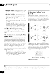
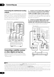
... for the connection.1 2 Connect the composite video output and the stereo analog audio outputs2 on your DVD player to the DVD/LD inputs on this receiver. Use a standard RCA video cable to connect to the composite video jack.4 DIGITAL AUDIO OUT OPTICAL 3 TV ANALOG AUDIO OUT R L VIDEO IN 4... OPT 2 (TV/SAT) input on this too. Use a coaxial digital audio cable for the connection. 4 Connect the MONITOR OUT video jack on this receiver. Use a standard RCA video cable3 and a stereo RCA phono cable for the connection. • If your DVD player has multichannel analog outputs, see The...
... for the connection.1 2 Connect the composite video output and the stereo analog audio outputs2 on your DVD player to the DVD/LD inputs on this receiver. Use a standard RCA video cable to connect to the composite video jack.4 DIGITAL AUDIO OUT OPTICAL 3 TV ANALOG AUDIO OUT R L VIDEO IN 4... OPT 2 (TV/SAT) input on this too. Use a coaxial digital audio cable for the connection. 4 Connect the MONITOR OUT video jack on this receiver. Use a standard RCA video cable3 and a stereo RCA phono cable for the connection. • If your DVD player has multichannel analog outputs, see The...
Owner's Manual
Page 14
... terrestrial digital TV tuners are all examples of so-called `set-top boxes'. OPTICAL COAXIAL R AUDIO L AV OUT VIDEO STB Note 1 The multichannel input can connect this receiver using the S-VIDEO TV/SAT jack. See Using the component video jacks on page 17 for the video connection.3 2 ...up Connecting the multichannel analog outputs For DVD Audio and SACD playback, your DVD player may have a digital audio output, omit this receiver as shown below.1 This receiver DIGITAL OUT IN OPT IN OPT 2 (TV/ SAT) IN OPT 1 (CD) OUT ASSIGNABLE DIGITAL IN IN ASSIGNABLE DIGITAL IN XM...
... terrestrial digital TV tuners are all examples of so-called `set-top boxes'. OPTICAL COAXIAL R AUDIO L AV OUT VIDEO STB Note 1 The multichannel input can connect this receiver using the S-VIDEO TV/SAT jack. See Using the component video jacks on page 17 for the video connection.3 2 ...up Connecting the multichannel analog outputs For DVD Audio and SACD playback, your DVD player may have a digital audio output, omit this receiver as shown below.1 This receiver DIGITAL OUT IN OPT IN OPT 2 (TV/ SAT) IN OPT 1 (CD) OUT ASSIGNABLE DIGITAL IN IN ASSIGNABLE DIGITAL IN XM...

Owner's Manual
Page 15
...coaxial or optical digital connection when connected to record from analog components. 15 En You'll need to make this to /from a digital component. This receiver DIGITAL OUT IN OPT IN OPT 2 (TV/ SAT) IN OPT 1 (CD) OUT ASSIGNABLE DIGITAL IN IN ASSIGNABLE DIGITAL IN XM IN IN COAX ...CD-R, MD, DAT, tape recorder or other audio components The number and kind of connections depends on the kind of spare audio inputs on this receiver. Use an optical cable to make this connection for components without a digital output, or if you 're connecting a recorder, connect the analog...
...coaxial or optical digital connection when connected to record from analog components. 15 En You'll need to make this to /from a digital component. This receiver DIGITAL OUT IN OPT IN OPT 2 (TV/ SAT) IN OPT 1 (CD) OUT ASSIGNABLE DIGITAL IN IN ASSIGNABLE DIGITAL IN XM IN IN COAX ...CD-R, MD, DAT, tape recorder or other audio components The number and kind of connections depends on the kind of spare audio inputs on this receiver. Use an optical cable to make this connection for components without a digital output, or if you 're connecting a recorder, connect the analog...

Owner's Manual
Page 16
...®, and the Windows logo are trademarks, or registered trademarks of Microsoft Corporation in the United States and/or other video components This receiver has audio/video inputs and outputs suitable for connecting analog or digital video recorders, including VCRs, DVDrecorders and HDD recorders. 1 Connect a... set of audio/video outputs on the recorder to the DVR/VCR AUDIO and VIDEO inputs on this receiver. must be able to output WMA9 Pro format audio signals through a coaxial or optical digital output. 4 If your video component only has...
...®, and the Windows logo are trademarks, or registered trademarks of Microsoft Corporation in the United States and/or other video components This receiver has audio/video inputs and outputs suitable for connecting analog or digital video recorders, including VCRs, DVDrecorders and HDD recorders. 1 Connect a... set of audio/video outputs on the recorder to the DVR/VCR AUDIO and VIDEO inputs on this receiver. must be able to output WMA9 Pro format audio signals through a coaxial or optical digital output. 4 If your video component only has...

Owner's Manual
Page 17
... are accessed via the front panel using a component video input, you made the rear panel connections. Press VIDEO/FRONT AUDIO and select F.AUDIO input. This receiver CD CD-R / TAPE / MD FM/AM XM SIRIUS AUX VIDEO VIDEO INPUT L AUDIO R DIGITAL IN MCACC/ AUDIO IN V L R VIDEO OUTPUT DIGITAL... English Deutsch Français Italiano Nederlands Español Connecting up the same way you must also have your TV connected to this receiver's COMPONENT VIDEO MONITOR OUT jacks. 1 Connect the component video outputs of your source to a set of component video inputs on your ...
... are accessed via the front panel using a component video input, you made the rear panel connections. Press VIDEO/FRONT AUDIO and select F.AUDIO input. This receiver CD CD-R / TAPE / MD FM/AM XM SIRIUS AUX VIDEO VIDEO INPUT L AUDIO R DIGITAL IN MCACC/ AUDIO IN V L R VIDEO OUTPUT DIGITAL... English Deutsch Français Italiano Nederlands Español Connecting up the same way you must also have your TV connected to this receiver's COMPONENT VIDEO MONITOR OUT jacks. 1 Connect the component video outputs of your source to a set of component video inputs on your ...

Owner's Manual
Page 19
... at least three speakers is recommended, and a complete setup is best. Also make sure the positive and negative (+/-) terminals on the receiver match those on page 69 if you have in the diagram) but everyone's home setup will work with an impedance of eight speakers ... IN SR P E SUB WOOFER A DVD / LD A PREOUT IN K S-VIDEO E R S FRONT MONITOR OUT COMPONENT VIDEO IN 2 LR SURROUND L CENTER R SURROUND BACK L B This receiver Powered subwoofer SW INPUT AC OUTLET Caution • Make sure that all the bare speaker wire is shown here but using only one surround back...
... at least three speakers is recommended, and a complete setup is best. Also make sure the positive and negative (+/-) terminals on the receiver match those on page 69 if you have in the diagram) but everyone's home setup will work with an impedance of eight speakers ... IN SR P E SUB WOOFER A DVD / LD A PREOUT IN K S-VIDEO E R S FRONT MONITOR OUT COMPONENT VIDEO IN 2 LR SURROUND L CENTER R SURROUND BACK L B This receiver Powered subwoofer SW INPUT AC OUTLET Caution • Make sure that all the bare speaker wire is shown here but using only one surround back...

Owner's Manual
Page 20
... to three feet) higher than your speakers as earthquakes. • Make sure no exposed speaker wire is touching the rear panel, this may cause the receiver to turn off automatically. Hints on speaker placement Speakers are hazardous when live. 03 Connecting up Make sure that the speaker cable you're using...
... to three feet) higher than your speakers as earthquakes. • Make sure no exposed speaker wire is touching the rear panel, this may cause the receiver to turn off automatically. Hints on speaker placement Speakers are hazardous when live. 03 Connecting up Make sure that the speaker cable you're using...

Owner's Manual
Page 21
...) connected. Total electrical power consumption of connected equipment should not exceed 100 W (0.8 A). • This unit should not be disconnected by the receiver's power switch. when on and off by removing the power plug from the wall socket when not in order to avoid overheating and fire risk.... B) shows orientation with two surround back speakers connected. 90~120 LS RS LS RS LS SB fig. This can also cause the receiver to malfunction. • Since a subwoofer or power amplifier can also refer to the 3-D speaker setup illustration on page 7. English Deutsch Franç...
...) connected. Total electrical power consumption of connected equipment should not exceed 100 W (0.8 A). • This unit should not be disconnected by the receiver's power switch. when on and off by removing the power plug from the wall socket when not in order to avoid overheating and fire risk.... B) shows orientation with two surround back speakers connected. 90~120 LS RS LS RS LS SB fig. This can also cause the receiver to malfunction. • Since a subwoofer or power amplifier can also refer to the 3-D speaker setup illustration on page 7. English Deutsch Franç...

Owner's Manual
Page 22
.../ SB ch RETRIEVER LOUDNESS PROCESSING TONE SIGNAL SPEAKERS SELECT TUNING/ STATION TUNER EDIT SETUP RETURN MULTI JOG VIDEO VIDEO INPUT L AUDIO R DIGITAL IN ENTER VSX-917V MULTI JOG AUX MCACC/ AUDIO IN STEREO/ ADVANCED F.S.SURR STANDARD SURROUND LISTENING MODE MASTER VOLUME DOWN UP 9 10 7 8 23 PHASE ACOUSTIC AUTO SURR/...page 31). 9 PHONES jack Use to connect headphones (when connected, there is no sound output from the speakers). 10 STANDBY/ON Switches the receiver between on and standby. 11 VIDEO INPUT See Connecting to the front panel video terminal on page 17.
.../ SB ch RETRIEVER LOUDNESS PROCESSING TONE SIGNAL SPEAKERS SELECT TUNING/ STATION TUNER EDIT SETUP RETURN MULTI JOG VIDEO VIDEO INPUT L AUDIO R DIGITAL IN ENTER VSX-917V MULTI JOG AUX MCACC/ AUDIO IN STEREO/ ADVANCED F.S.SURR STANDARD SURROUND LISTENING MODE MASTER VOLUME DOWN UP 9 10 7 8 23 PHASE ACOUSTIC AUTO SURR/...page 31). 9 PHONES jack Use to connect headphones (when connected, there is no sound output from the speakers). 10 STANDBY/ON Switches the receiver between on and standby. 11 VIDEO INPUT See Connecting to the front panel video terminal on page 17.


