Pioneer AVM-P505R Support and Manuals
Get Help and Manuals for this Pioneer item
View All Support Options Below
Free Pioneer AVM-P505R manuals!
Problems with Pioneer AVM-P505R?
Ask a Question
Free Pioneer AVM-P505R manuals!
Problems with Pioneer AVM-P505R?
Ask a Question
Popular Pioneer AVM-P505R Manual Pages
Service Manual - Page 1

... Meguro-ku, Tokyo 153-8654, Japan
PIONEER ELECTRONICS SERVICE INC. P.O.Box 1760, Long Beach, CA 90801-1760 U.S.A. PCB CONNECTION DIAGRAM 14 5. GENERAL INFORMATION 31
7.1 IC 31 7.2 BLOCK DIAGRAM 36 8. Service
Manual
ORDER NO. EXPLODED VIEWS AND PARTS LIST 2 3. SAFETY INFORMATION 2 2. PIONEER ELECTRONIC [EUROPE] N.V. CRT2215
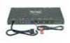
AUDIO VISUAL MASTER UNIT
AVM-P505R UC
CONTENTS
1.
Service Manual - Page 2

... risk trying to do so and refer the repair to perform the repair of the product and may cause birth defects or other components which may void the warranty. When servicing or handling circuit boards and other reproductive harm (California Health and Safety Code, Section 25249.5). AVM-P505R
1. Qualified technicians have the necessary test equipment and...
Service Manual - Page 3

AVM-P505R
NOTE: - Parts marked by "*"are generally unavailable because they are used for disassembly. - CDE5579 CDE5583 CDH1248 CEA2346 CZE3198
Mark No. Description
21 Polyethylene Bag 22 Battery 23 Carton 24 Sub Carton 25 Contain Box
Part No.
Description
1 Cord 2 Cord Assy 3 Antenna Cable 4 Bracket Assy 5 Screw Assy
Part No. PACKING SECTION PARTS LIST
Mark No. Screws...
Service Manual - Page 6

1
2
3
4
AVM-P505R
3. SCHEMATIC DIAGRAM
3.1 TUNER AMP UNIT(GUIDE PAGE)
A Note: When ordering service parts, be sure to refer to "EXPLODED VIEWS AND PARTS LIST" or "ELECTRICAL PARTS LIST". A-a
Large size
A-a
A-b
SCH diagram
AUDIO SIGNAL COMPOSITE VIDEO SIGNAL Y SIGNAL COLOR SIGNAL RED SIGNAL SIYNCRONIZING SIGNAL
A-a A-b Guide page
B
Detailed page
A-a
A-b
C
TUNU 2TUNU
D
A 6
1
2
...
Service Manual - Page 15

...for several destination.
The parts mounted on this PCB include all necessary
parts for respective destinations, be sure to check with the schematic diagram. Viewpoint of PCB diagrams
SIDE A
Connector Capacitor A
SIDE A
P.C.Board Chip Part
SIDE B
CORD ASSY
B
C
P-BUS OUT
SUBWOOFER OUT
L
R
REAR OUT
L
R
FRONT OUT
L
R
5
6
7
D
A 15 8 5
6
7
8
AVM-P505R
NOTE FOR PCB DIAGRAMS...
Service Manual - Page 20

AVM-P505R
5.
ELECTRICAL PARTS LIST
NOTE: - Chip Resistor RS1/_S___J,RS1/__S___J
Chip Capacitor (except for CQS.....) CKS....., CCS....., CSZS.....
=====Circuit Symbol and No.===Part...DTC323TK
IMD2A DTA124EK DTC343TK DTC343TK IMH3A
IMH3A IMH3A DTC323TK DTC323TK DTC323TK
=====Circuit Symbol and No.===Part Name
Q 404 Q 405 Q 406 Q 407 Q 408
Transistor Transistor Transistor Transistor ...
Service Manual - Page 38

...metal) body. IP-Bus cable
IP-Bus input (Blue)
Green
RGB input To a Pioneer unit that are not connected to speakers.
Please be sure to connect to a muting line ...20 pin RGB output terminal. Pinch tightly with power regardless of Pioneer unit that the vehicle is stopped. AVM-P505R
8. OPERATIONS AND SPECIFICATIONS
8.1 OPERATIONS
38
Basic System Connection
+ side Earth side
Blue/yellow...
Service Manual - Page 40
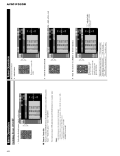
... when a stereo station is set to OFF.
Tune the receiver...set to a higher or lower frequency. Select Tuner.
- Select the desired band.
3. Manual Tuning (step by changing the length of Tuner 1. Tuner Operation
Basic Operation of time you select the tuning by step) Seek Tuning (automatically) Manual Tuning (continuously)
0.3 seconds or less 0.3 - 2 seconds 2 seconds or more . AVM-P505R...
Service Manual - Page 41

...APF ® MULTI ST.* ® LOCAL ® TA**® TA SEEK **® SEEK-SELECT
* The setting of the "MULTI-ST." Note: • After entering the Function Menu, if you do not perform an ...instructions on how to the TA mode. Turn the source OFF. Refer to "Using RDS/ID LOGIC" for 1 second Note: • During FORMAT SEEK, reception will not be changed . Raise or lower the volume. AVM-P505R...
Service Manual - Page 42

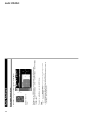
...type.
Note:
• The multi-CD player may perform a preparatory operation, such as "ERROR-14" is displayed according to the multi-CD player owner's manual.
• If there are no disc in the multi-CD player magazine, "NO DISC"...
"6", "12" or "50" is displayed. Select the multi-CD player source. AVM-P505R
42
Using Multi-CD Players
This product can control one or more multi-CD players.
Service Manual - Page 43

...stops part way ...multi-CD player instructions carefully, and set the address ...switches properly.
• Select the multi-CD player you start playing a disc on a 50-Disc type multi-CD player before reading of information on all the discs in . Using Multi-CD Players
3.
When two or more multi-CD players are installed...CD Player. Press button 3.)
AVM-P505R
43
Hold for 2 seconds ...
Service Manual - Page 44
... cancel the Audio Menu, press the BAND button. Each press of the AUDIO button selects the mode in the SUBWOOFER1.
Each press changes the Mode... AVM-P505R
44
Audio Adjustment
Entering the Audio Menu
• Select the mode you do not perform an operation which 30 seconds, the
Audio Menu is automatically...
Service Manual - Page 45

... in red.
Shift the balance to the left to right.
3. Note: • When using 2-speaker system, set FADER to the front or rear speakers. "LEFT +9" is displayed as it moves from front to
The tone for... Adjustment
Bass/Middle/Treble Adjustment
This function allows you to select a Fader/Balance setting that provides ideal listening conditions in the Audio Menu.
2.
AVM-P505R
45
Service Manual - Page 46

Switch the Loudness function ON or OFF. "LOUD" To cancel the Audio Menu, press the BAND button.
AVM-P505R
46
Audio Adjustment
Loudness Adjustment
The Loudness function compensates for deficiencies in the Audio Menu. 2. Select the Loudness mode (LOUD) in the low and high sound ranges at low volume. 1.
Service Manual - Page 47

... 18 mV (S/N: 20 dB) Selectivity 50 dB (±10 kHz)
Video Composit input level 1V/75 ½ (±0.2 V) Composit output level 1V/75 ½ (±0.2 V)
8.2 SPECIFICATIONS
AVM-P505R
Pioneer AVM-P505R Reviews
We have not received any reviews for Pioneer yet.