
Service Manual
Page 1
... VIEWS AND PARTS LIST 4 3.BLOCK DIAGRAM AND SCHEMATIC 12 4.PCB CONNECTION DIAGRAM 26 5.ELECTRICAL PARTS LIST 34 6.ADJUSTMENT 40 7.GENERAL INFORMATION 48 7.1 DIAGNOSIS 48 7.1.1 DISASSEMBLY 48 7.1.2 CONNECTOR FUNCTION DESCRIPTION . . . . .51 7.2 PARTS 52 7.2.1 IC 52 7.2.2 DISPLAY 62 7.3 OPERATION FLOW CHART 63 7.4CLEANING 64 8. CRT2771 DEH-P440/XN/UC MULTI-CD CONTROL HIGH POWER CD PLAYRE WITH FM/AM TUNER DEH-P440/XN/UC DEH-P4400/XN/UC DEH-P440/XN/X/UNC/UC This service manual should...
... VIEWS AND PARTS LIST 4 3.BLOCK DIAGRAM AND SCHEMATIC 12 4.PCB CONNECTION DIAGRAM 26 5.ELECTRICAL PARTS LIST 34 6.ADJUSTMENT 40 7.GENERAL INFORMATION 48 7.1 DIAGNOSIS 48 7.1.1 DISASSEMBLY 48 7.1.2 CONNECTOR FUNCTION DESCRIPTION . . . . .51 7.2 PARTS 52 7.2.1 IC 52 7.2.2 DISPLAY 62 7.3 OPERATION FLOW CHART 63 7.4CLEANING 64 8. CRT2771 DEH-P440/XN/UC MULTI-CD CONTROL HIGH POWER CD PLAYRE WITH FM/AM TUNER DEH-P440/XN/UC DEH-P4400/XN/UC DEH-P440/XN/X/UNC/UC This service manual should...
Service Manual
Page 2
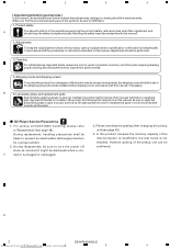
..., radio and noise, and other parts requiring cleaning, proper cleaning should be performed to "Disassembly"(see page 42). 4. Shipping mode and shipping screws To protect the product from www1 .Manualslib.com manuals search engin2e 3 4 C nector is not installed. Cleaning For optical pickups, tape-deck heads, lenses and mirrors used . - B 5. CD Player Service Precautions 1. D 2 DEH-P440/XN/UC Downloaded from damages or failures that adjustments, settings or...
..., radio and noise, and other parts requiring cleaning, proper cleaning should be performed to "Disassembly"(see page 42). 4. Shipping mode and shipping screws To protect the product from www1 .Manualslib.com manuals search engin2e 3 4 C nector is not installed. Cleaning For optical pickups, tape-deck heads, lenses and mirrors used . - B 5. CD Player Service Precautions 1. D 2 DEH-P440/XN/UC Downloaded from damages or failures that adjustments, settings or...
Service Manual
Page 5
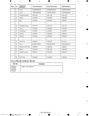
..., English, French,Spanish CRD3543, CRD3556, CRD3557 C Downloaded from www.Manualslib.com 5manuals search engine DEH-P440/XN/UC 6 7 D 5 8 5 6 7 8 Mark NO Symbol and Description DEH-P440/XN/UC DEH-P4400/XN/UC DEH-P44/XN/UC 7 Screw CRZ50P090FMC CRZ50P090FMC CRZ50P090FMC 8... CXB3520 Not used 18 Screw BPZ20P060FZK BPZ20P060FZK BPZ20P060FZK B 19 Remote Control Unit CXB8743 CXB8743 CXB6797 * 20 Battery CEX1065 CEX1065 CEX1065 21 Accessory Assy CEA2773 CEA2773 CEA2773 22 Earth Plate CNC9450 CNC9450 CNC9450 Owner's Manual,Installation Manual Part No.
..., English, French,Spanish CRD3543, CRD3556, CRD3557 C Downloaded from www.Manualslib.com 5manuals search engine DEH-P440/XN/UC 6 7 D 5 8 5 6 7 8 Mark NO Symbol and Description DEH-P440/XN/UC DEH-P4400/XN/UC DEH-P44/XN/UC 7 Screw CRZ50P090FMC CRZ50P090FMC CRZ50P090FMC 8... CXB3520 Not used 18 Screw BPZ20P060FZK BPZ20P060FZK BPZ20P060FZK B 19 Remote Control Unit CXB8743 CXB8743 CXB6797 * 20 Battery CEX1065 CEX1065 CEX1065 21 Accessory Assy CEA2773 CEA2773 CEA2773 22 Earth Plate CNC9450 CNC9450 CNC9450 Owner's Manual,Installation Manual Part No.
Service Manual
Page 7
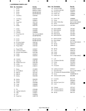
...(IC361) 82 Panel 83 Remote Control Unit 84 Cover PAL007A CNS6935 CXB8743 CNS7068 85 Clamper 86 Connector(CN701) 87 Connector(CN331) 88 Spring CEF1007 CKS3408 CKS3598 CBL1470 D Downloaded from www.Manualslib.com 5manuals search engine DEH-P440/XN/UC 6 7 7 8 Description 1 Screw 2 Screw 3 Screw 4 Screw 5 Cord Assy 6 Cord Assy 7 Cable 8 Fuse(10A) 9 Case 10 Holder 11 Holder 12 Cushion 13 Insulator 14 Tuner Amp Unit 15 Screw...
...(IC361) 82 Panel 83 Remote Control Unit 84 Cover PAL007A CNS6935 CXB8743 CNS7068 85 Clamper 86 Connector(CN701) 87 Connector(CN331) 88 Spring CEF1007 CKS3408 CKS3598 CBL1470 D Downloaded from www.Manualslib.com 5manuals search engine DEH-P440/XN/UC 6 7 7 8 Description 1 Screw 2 Screw 3 Screw 4 Screw 5 Cord Assy 6 Cord Assy 7 Cable 8 Fuse(10A) 9 Case 10 Holder 11 Holder 12 Cushion 13 Insulator 14 Tuner Amp Unit 15 Screw...
Service Manual
Page 13
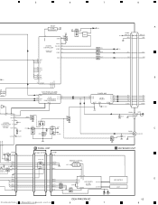
... Lch Q351 REAR/SW CSENS ILMPW VDD REMIN 77 20 B.U Q751 CN750 ILB+ 7 B PANEL UNIT CN1950 CN1951 7 4 CN1901 9 IL+B C KEYBOARD UNIT VDD S750 DETACH ENSE SW Q753 CSENS 4 EJECT 8 FILM+ B.U 5 SW5V 10 Q750 9 EJECT SW S1950 4 3 8 6 5 10 5 9 CSENS 10 µGND 7 SW5V 8 REMOTE CONTROL SENSOR 1 OPT... 14 ROT1 12 14 8 5 KYDT S1922 8 KYDT 3 LCD DRIVER KEY DATA RDT1 12 7 6 X0 X1901 IC 1903 PD6294A ROT0 13 13 9 4 RDT0 Q1905 2 X1 DIMMER LCD DATA LCD BL+B 2 2 2 11 BL+B 7 Downloaded from www.Manualslib.com 5manuals search engine DEH-P440/XN/UC 6 7 13 8
... Lch Q351 REAR/SW CSENS ILMPW VDD REMIN 77 20 B.U Q751 CN750 ILB+ 7 B PANEL UNIT CN1950 CN1951 7 4 CN1901 9 IL+B C KEYBOARD UNIT VDD S750 DETACH ENSE SW Q753 CSENS 4 EJECT 8 FILM+ B.U 5 SW5V 10 Q750 9 EJECT SW S1950 4 3 8 6 5 10 5 9 CSENS 10 µGND 7 SW5V 8 REMOTE CONTROL SENSOR 1 OPT... 14 ROT1 12 14 8 5 KYDT S1922 8 KYDT 3 LCD DRIVER KEY DATA RDT1 12 7 6 X0 X1901 IC 1903 PD6294A ROT0 13 13 9 4 RDT0 Q1905 2 X1 DIMMER LCD DATA LCD BL+B 2 2 2 11 BL+B 7 Downloaded from www.Manualslib.com 5manuals search engine DEH-P440/XN/UC 6 7 13 8
Service Manual
Page 14
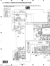
A A-a Large size A-a A-b SCH diagram FM(100%):-19.5dBs AM(30%) :-30dBs A-a A-b Guide page A-a A-b Detailed page FM/AM TUNER UNIT CONTROL UNIT D KEYBOARD UNIT C B DSP-201M C D CD:+4.1dBs AB 14 Downloaded from www1 .Manualslib.com manuals search engin2e DEH-P440/XN/UC 3 P4400,P44 PE5246A SYSTEM CONTROLLER EJECT B PANEL UNIT 4 DETACH SENSE S The > mark fo the importance Therefore, whe identical desig 1 2 3 4 3.2 OVERALL CONNECTION DIAGRAM(GUIDE PAGE) Note: When ordering service parts, be sure to refer to " EXPLODED VIEWS AND PARTS LIST" or "ELECTRICAL PARTS LIST".
A A-a Large size A-a A-b SCH diagram FM(100%):-19.5dBs AM(30%) :-30dBs A-a A-b Guide page A-a A-b Detailed page FM/AM TUNER UNIT CONTROL UNIT D KEYBOARD UNIT C B DSP-201M C D CD:+4.1dBs AB 14 Downloaded from www1 .Manualslib.com manuals search engin2e DEH-P440/XN/UC 3 P4400,P44 PE5246A SYSTEM CONTROLLER EJECT B PANEL UNIT 4 DETACH SENSE S The > mark fo the importance Therefore, whe identical desig 1 2 3 4 3.2 OVERALL CONNECTION DIAGRAM(GUIDE PAGE) Note: When ordering service parts, be sure to refer to " EXPLODED VIEWS AND PARTS LIST" or "ELECTRICAL PARTS LIST".
Service Manual
Page 15
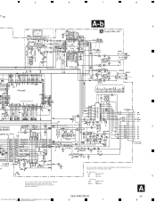
... 10k ohms D *Capacitors Code Practical value 103 0.01uF 101/10 100uF/10V A DEH-P440/XN/UC 6 7 15 8 T" or 5 IP-BUS:+2.2dBs 0,P44 PE5246A SYSTEM CONTROLLER ECT DETACH SENSE SW FM(100%):-19.5dBs AM(30%): -30dBs CD: +4.1dBs IP-BUS: +2.2dBs 472/16 6 7 8 A-b A P440 only A TUNER AMP UNIT P440 only PML009A(P440) PML008A(P4400,P44) P440 only P440 only P440 only P440 only FM(100%): +3.6dBs...
... 10k ohms D *Capacitors Code Practical value 103 0.01uF 101/10 100uF/10V A DEH-P440/XN/UC 6 7 15 8 T" or 5 IP-BUS:+2.2dBs 0,P44 PE5246A SYSTEM CONTROLLER ECT DETACH SENSE SW FM(100%):-19.5dBs AM(30%): -30dBs CD: +4.1dBs IP-BUS: +2.2dBs 472/16 6 7 8 A-b A P440 only A TUNER AMP UNIT P440 only PML009A(P440) PML008A(P4400,P44) P440 only P440 only P440 only P440 only FM(100%): +3.6dBs...
Service Manual
Page 19
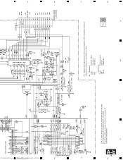
... or capacitance values are expressed in codes: Ex. *Resistors Code Practical value 123 12k ohms 103 10k ohms *Capacitors Code Practical value 103 0.01uF 101/10 100uF/10V A-a A-b A 8 7 6 5 D A-b 19 8 3 7 DEH-P440/XN/UC 6 2 Downloaded from www.Manualslib.com 5manuals search engine STEM CONTROLLER DETACH SENSE SW The > mark found on some component parts indicates the importance of the...
... or capacitance values are expressed in codes: Ex. *Resistors Code Practical value 123 12k ohms 103 10k ohms *Capacitors Code Practical value 103 0.01uF 101/10 100uF/10V A-a A-b A 8 7 6 5 D A-b 19 8 3 7 DEH-P440/XN/UC 6 2 Downloaded from www.Manualslib.com 5manuals search engine STEM CONTROLLER DETACH SENSE SW The > mark found on some component parts indicates the importance of the...
Service Manual
Page 34
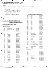
.... Part Name Parts No. A Chip Resistor RS1/_S___J,RS1/__S___J Chip Capacitor (except for CQS.....) CKS....., CCS....., CSZS..... D 510 D 750 D 751 D 752 D 753 Diode Diode Diode Diode Diode HZS9L(B1) 1SS270 1SS270 DAP202U DAN202U Unit Number:CWM8015(DEH-P440) :CWM8014(DEH-P4400,P44) Unit Name:Tuner Amp Unit B MISCELLANEOUS IC 301 IC 301 IC 361 IC 601 IC 603 IC(DEH-P440) IC(DEH...
.... Part Name Parts No. A Chip Resistor RS1/_S___J,RS1/__S___J Chip Capacitor (except for CQS.....) CKS....., CCS....., CSZS..... D 510 D 750 D 751 D 752 D 753 Diode Diode Diode Diode Diode HZS9L(B1) 1SS270 1SS270 DAP202U DAN202U Unit Number:CWM8015(DEH-P440) :CWM8014(DEH-P4400,P44) Unit Name:Tuner Amp Unit B MISCELLANEOUS IC 301 IC 301 IC 361 IC 601 IC 603 IC(DEH-P440) IC(DEH...
Service Manual
Page 40
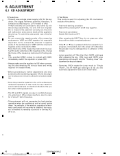
... connected to oscillate because of the fol- CRG move and 100TR jump operations are brought into the "Tracking close" status when the key is usual- ADJUSTMENT 6.1 CD ADJUSTMENT 1) Precautions A • This unit uses a single power supply (+5V) for adjusting the CD mechanism module of the device. • Test mode starting procedure Reset while pressing the 4 and 6 keys together. • Test mode cancellation Switch...
... connected to oscillate because of the fol- CRG move and 100TR jump operations are brought into the "Tracking close" status when the key is usual- ADJUSTMENT 6.1 CD ADJUSTMENT 1) Precautions A • This unit uses a single power supply (+5V) for adjusting the CD mechanism module of the device. • Test mode starting procedure Reset while pressing the 4 and 6 keys together. • Test mode cancellation Switch...
Service Manual
Page 41
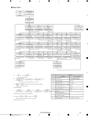
... / S. RF Gain switching/Offset adjustment display/ T.Balance adjustment/T.OPN MODE F.CLS,S.Curve /Rough Servo F,T,RF AGC and RF AGC/ (ITP) SPDL 1X/2X switching (Double-speed compatibility only) - *7) TRK/MIN/SEC F.AGC T.AGC Gain Gain F.Bias RF AGC Gain - Error rate measurement - [6] F.Mode switching/T.CLS/CRG,TR Jump switching Auto/Manual switching *8) CRG motor voltage = 2 [V] D Downloaded from www.Manualslib.com 5manuals search engine DEH-P440/XN/UC 6 7 41...
... / S. RF Gain switching/Offset adjustment display/ T.Balance adjustment/T.OPN MODE F.CLS,S.Curve /Rough Servo F,T,RF AGC and RF AGC/ (ITP) SPDL 1X/2X switching (Double-speed compatibility only) - *7) TRK/MIN/SEC F.AGC T.AGC Gain Gain F.Bias RF AGC Gain - Error rate measurement - [6] F.Mode switching/T.CLS/CRG,TR Jump switching Auto/Manual switching *8) CRG motor voltage = 2 [V] D Downloaded from www.Manualslib.com 5manuals search engine DEH-P440/XN/UC 6 7 41...
Service Manual
Page 44
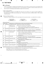
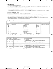
... calls from the A users and also for the system), error codes are written to DMIN and DSEC. Focus can 't be moved from www1 .Manualslib.com manuals search engin2e 3 4 CD signal error. 17 Electricity Setup NG AGC protection doesn't work in these errors). 1 2 3 4 6.3 TEST MODE - This arrangement is selected for the CSMOD (CD mode area for facilitating trouble analysis and repair work . munication Error → Failure on...
... calls from the A users and also for the system), error codes are written to DMIN and DSEC. Focus can 't be moved from www1 .Manualslib.com manuals search engin2e 3 4 CD signal error. 17 Electricity Setup NG AGC protection doesn't work in these errors). 1 2 3 4 6.3 TEST MODE - This arrangement is selected for the CSMOD (CD mode area for facilitating trouble analysis and repair work . munication Error → Failure on...
Service Manual
Page 45
... use of the [SOURCE] key, and inser disc. Time/Err.No. Tracking Close Scan - 2- Downloaded from the key. 2 Select S-CD for the normal mode. (3) Cause of whether the S-CD is displayed. A These displays and functions are prepared for 500 msec. → Damages/stains on disc, vibrations or failure on /off . 3 After the above operations, the new test mode remains on irrespective of Error and Error Code Code...
... use of the [SOURCE] key, and inser disc. Time/Err.No. Tracking Close Scan - 2- Downloaded from the key. 2 Select S-CD for the normal mode. (3) Cause of whether the S-CD is displayed. A These displays and functions are prepared for 500 msec. → Damages/stains on disc, vibrations or failure on /off . 3 After the above operations, the new test mode remains on irrespective of Error and Error Code Code...
Service Manual
Page 47
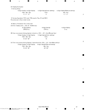
... time. ((B)←→(C) : Auto/Manual key) 8-digit display, 6-digit display 4-digit display(Manual setting) TNO. Min Sec TNO. 10 40' 05" 10 B (C) Error occurrence timing display in track no. ((B)←→(C) : Auto/Manual key) 8-digit display, 6-digit display 4-digit display(Auto setting) TNO. Min Sec Min Sec 10 40' 05" 40' 05" C Downloaded from www.Manualslib.com 5manuals search engine DEH-P440/XN/UC 6 7 D 47 8 5 6 7 8 (5) Display Examples 1) During Setup 8-digit display, 6-digit display 4-digit display(Auto setting) 4-digit display(Manual setting...
... time. ((B)←→(C) : Auto/Manual key) 8-digit display, 6-digit display 4-digit display(Manual setting) TNO. Min Sec TNO. 10 40' 05" 10 B (C) Error occurrence timing display in track no. ((B)←→(C) : Auto/Manual key) 8-digit display, 6-digit display 4-digit display(Auto setting) TNO. Min Sec Min Sec 10 40' 05" 40' 05" C Downloaded from www.Manualslib.com 5manuals search engine DEH-P440/XN/UC 6 7 D 47 8 5 6 7 8 (5) Display Examples 1) During Setup 8-digit display, 6-digit display 4-digit display(Auto setting) 4-digit display(Manual setting...
Service Manual
Page 54
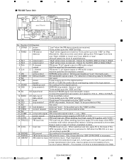
... used 2 dsens I Grille detach sense input A 3 NC Not used 4 EJECTIN I Eject sense input 5 TESTIN I Test program mode input 6 LCDPW O LCD back light power supply control output 7 TELIN I Telephone mute input 8 isens I Illumination sense input 9 FLPILM O Flap illumination input 10 DALMON For consumption low-current 11 reset I Reset input 12 XT2 Not used (open) 13 XT1 Clock connection pin 14 VSS(GND) GND 15 X2 Crystal oscillator connection pin 16 X1 Crystal oscillator connection pin 17 REGOFF Regulator operation specification...
... used 2 dsens I Grille detach sense input A 3 NC Not used 4 EJECTIN I Eject sense input 5 TESTIN I Test program mode input 6 LCDPW O LCD back light power supply control output 7 TELIN I Telephone mute input 8 isens I Illumination sense input 9 FLPILM O Flap illumination input 10 DALMON For consumption low-current 11 reset I Reset input 12 XT2 Not used (open) 13 XT1 Clock connection pin 14 VSS(GND) GND 15 X2 Crystal oscillator connection pin 16 X1 Crystal oscillator connection pin 17 REGOFF Regulator operation specification...
Service Manual
Page 57
5 6 7 8 - Pin Name I/O Function and Operation 1 VCC Power supply voltage terminal 2 RFGC I RF amplitude adjustment control signal terminal 3 GMAD I AGC amplifier frequency characteristic adjustment terminal 4 FNI I Main beam amplifier input terminal A 5 FPI I Main beam amplifier input terminal 6 TPI I Sub beam amplifier input terminal 7 TNI I Sub beam amplifier input terminal 8 MDI O Monitor photodiode amplifier input terminal 9 LDO I Laser diode amplifier output terminal 10 SEL I APC circuit ON/OFF signal, LDO terminal control input terminal and bottom and...
5 6 7 8 - Pin Name I/O Function and Operation 1 VCC Power supply voltage terminal 2 RFGC I RF amplitude adjustment control signal terminal 3 GMAD I AGC amplifier frequency characteristic adjustment terminal 4 FNI I Main beam amplifier input terminal A 5 FPI I Main beam amplifier input terminal 6 TPI I Sub beam amplifier input terminal 7 TNI I Sub beam amplifier input terminal 8 MDI O Monitor photodiode amplifier input terminal 9 LDO I Laser diode amplifier output terminal 10 SEL I APC circuit ON/OFF signal, LDO terminal control input terminal and bottom and...
Service Manual
Page 59
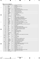
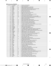
5 6 7 8 - Pin Functions(TC9495F2) Pin No. Pin Name I/O Function and Operation 1 TESTO Test mode terminal 2 hso O Replay speed flag output terminal 3 uhso O Replay speed flag output terminal 4 EMPH O Emphasis flag output terminal for sub code Q data A 5 LRCK O Channel clock (44.1 kHz) output terminal 6 VSS Digital ground terminal 7 BCK O Bit clock output terminal 8 AOUT O Digital audio data output terminal 9 DOUT O Digital out output terminal 10 MBOV O Buffer memory over signal output terminal 11 IPF O Correction...
5 6 7 8 - Pin Functions(TC9495F2) Pin No. Pin Name I/O Function and Operation 1 TESTO Test mode terminal 2 hso O Replay speed flag output terminal 3 uhso O Replay speed flag output terminal 4 EMPH O Emphasis flag output terminal for sub code Q data A 5 LRCK O Channel clock (44.1 kHz) output terminal 6 VSS Digital ground terminal 7 BCK O Bit clock output terminal 8 AOUT O Digital audio data output terminal 9 DOUT O Digital out output terminal 10 MBOV O Buffer memory over signal output terminal 11 IPF O Correction...
Service Manual
Page 61
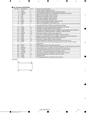
... power Power supply pin for the RDS. 9 NC Not used 18 LDET O lock detector Active at "Low". When seeking local low, apply 5V to the "VDD" at 47kΩ 20 NC Not used when taking diver FIX trigger from www.Manualslib.com 5manuals search engine DEH-P440/XN/UC 6 7 61 8 For detection of ordinary marketed models. 25 LOCL I /O signal level Received...
... power Power supply pin for the RDS. 9 NC Not used 18 LDET O lock detector Active at "Low". When seeking local low, apply 5V to the "VDD" at 47kΩ 20 NC Not used when taking diver FIX trigger from www.Manualslib.com 5manuals search engine DEH-P440/XN/UC 6 7 61 8 For detection of ordinary marketed models. 25 LOCL I /O signal level Received...
Service Manual
Page 65
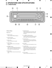
... through all of functions. 1 DISPLAY button Press to select a natural sound with presence. ! VOLUME button When you press VOLUME, it extends outward so that it again. Rotate to increase or decrease the volume. @ CLOCK button Press to open the front panel. Press to select functions. 9 SOURCE button 3 OPEN button Press to switch clock display on by selecting a source. Also used for controlling functions. 6 SFEQ button Press to select different displays. 8 1-6 (PRESET TUNING) buttons Press for preset tuning and disc number 2 FUNCTION button search when using a multi-CD player...
... through all of functions. 1 DISPLAY button Press to select a natural sound with presence. ! VOLUME button When you press VOLUME, it extends outward so that it again. Rotate to increase or decrease the volume. @ CLOCK button Press to open the front panel. Press to select functions. 9 SOURCE button 3 OPEN button Press to switch clock display on by selecting a source. Also used for controlling functions. 6 SFEQ button Press to select different displays. 8 1-6 (PRESET TUNING) buttons Press for preset tuning and disc number 2 FUNCTION button search when using a multi-CD player...
Service Manual
Page 67
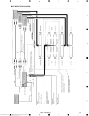
... speaker Right Rear Speaker Rear Speaker DEH-P440/XN/UC 7 7 Perform these connections when using a different amp (sold separately) IP-BUS cable Antenna jack IP-BUS input (Blue) Yellow To terminal always supplied with power regardless of the power amp or Auto-antenna relay control terminal (max. 300mA 12 V DC). Front speaker System remote control Front speaker Red To electric terminal controlled by ignition switch (12 V DC) ON/OFF. Subwoofer Subwoofer 8 D 67 8 A B C Orange/white To lighting switch terminal. With a 2 speaker system, do not connect...
... speaker Right Rear Speaker Rear Speaker DEH-P440/XN/UC 7 7 Perform these connections when using a different amp (sold separately) IP-BUS cable Antenna jack IP-BUS input (Blue) Yellow To terminal always supplied with power regardless of the power amp or Auto-antenna relay control terminal (max. 300mA 12 V DC). Front speaker System remote control Front speaker Red To electric terminal controlled by ignition switch (12 V DC) ON/OFF. Subwoofer Subwoofer 8 D 67 8 A B C Orange/white To lighting switch terminal. With a 2 speaker system, do not connect...


