
Service Manual
Page 1
...CX-977 CRT2624 S9 CD Mech. PIONEER CORPORATION 4-1, Meguro 1-Chome, Meguro-ku, Tokyo 153-8654, Japan PIONEER ELECTRONICS (USA) INC. CRT2771 DEH-P440/XN/UC MULTI-CD CONTROL HIGH POWER CD PLAYRE WITH FM/AM TUNER DEH-P440/XN/UC DEH-P4400/XN/UC DEH-P440/XN/X/UNC/UC This service manual ...should be used together with the following manual(s): Model No. Service Manual EQ AUDIO SELECT SFEQ ORDER NO. Description,Disassembly CONTENTS 1.SAFETY INFORMATION 3 2.EXPLODED VIEWS AND PARTS LIST 4 3.BLOCK DIAGRAM AND ...
...CX-977 CRT2624 S9 CD Mech. PIONEER CORPORATION 4-1, Meguro 1-Chome, Meguro-ku, Tokyo 153-8654, Japan PIONEER ELECTRONICS (USA) INC. CRT2771 DEH-P440/XN/UC MULTI-CD CONTROL HIGH POWER CD PLAYRE WITH FM/AM TUNER DEH-P440/XN/UC DEH-P4400/XN/UC DEH-P440/XN/X/UNC/UC This service manual ...should be used together with the following manual(s): Model No. Service Manual EQ AUDIO SELECT SFEQ ORDER NO. Description,Disassembly CONTENTS 1.SAFETY INFORMATION 3 2.EXPLODED VIEWS AND PARTS LIST 4 3.BLOCK DIAGRAM AND ...
Service Manual
Page 14
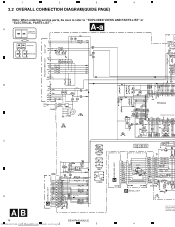
1 2 3 4 3.2 OVERALL CONNECTION DIAGRAM(GUIDE PAGE) Note: When ordering service parts, be sure to refer to " EXPLODED VIEWS AND PARTS LIST" or "ELECTRICAL PARTS LIST". A A-a Large size A-a A-b SCH diagram FM(100%):-19.5dBs AM(30%) :-30dBs A-a A-b Guide page A-a A-b Detailed page FM/AM TUNER UNIT CONTROL UNIT D KEYBOARD UNIT C B DSP-201M C D CD:+4.1dBs AB 14 Downloaded from www1 .Manualslib.com manuals search engin2e DEH-P440/XN/UC 3 P4400,P44 PE5246A SYSTEM CONTROLLER EJECT B PANEL UNIT 4 DETACH SENSE S The > mark fo the importance Therefore, whe identical desig
1 2 3 4 3.2 OVERALL CONNECTION DIAGRAM(GUIDE PAGE) Note: When ordering service parts, be sure to refer to " EXPLODED VIEWS AND PARTS LIST" or "ELECTRICAL PARTS LIST". A A-a Large size A-a A-b SCH diagram FM(100%):-19.5dBs AM(30%) :-30dBs A-a A-b Guide page A-a A-b Detailed page FM/AM TUNER UNIT CONTROL UNIT D KEYBOARD UNIT C B DSP-201M C D CD:+4.1dBs AB 14 Downloaded from www1 .Manualslib.com manuals search engin2e DEH-P440/XN/UC 3 P4400,P44 PE5246A SYSTEM CONTROLLER EJECT B PANEL UNIT 4 DETACH SENSE S The > mark fo the importance Therefore, whe identical desig
Service Manual
Page 15
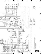
... 5manuals search engine For resistors and capacitors in the circuit diagrams, their resistance values or capacitance values are expressed in codes: Ex. *Resistors Code Practical value 123 12k ohms 103 10k ohms D *Capacitors Code Practical value 103 0.01uF 101/10 100uF/10V A DEH-P440/XN/UC 6 7 15 8 T" or 5 IP-BUS:+2.2dBs 0,P44 PE5246A...
... 5manuals search engine For resistors and capacitors in the circuit diagrams, their resistance values or capacitance values are expressed in codes: Ex. *Resistors Code Practical value 123 12k ohms 103 10k ohms D *Capacitors Code Practical value 103 0.01uF 101/10 100uF/10V A DEH-P440/XN/UC 6 7 15 8 T" or 5 IP-BUS:+2.2dBs 0,P44 PE5246A...
Service Manual
Page 19
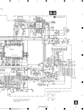
D A-b 19 8 3 7 DEH-P440/XN/UC 6 2 Downloaded from www.Manualslib.com 5manuals search engine STEM CONTROLLER DETACH SENSE SW The > mark found on some component parts indicates the importance ... > FUSE CEK1136 10A FM(100%):+29.6dBs AM(30%):+19.1dBs CD:+36.2dBs IP-BUS:+36.3dBs For resistors and capacitors in the circuit diagrams, their resistance values or capacitance values are expressed in codes: Ex. *Resistors Code Practical value 123 12k ohms 103 10k ohms *Capacitors Code Practical value...
D A-b 19 8 3 7 DEH-P440/XN/UC 6 2 Downloaded from www.Manualslib.com 5manuals search engine STEM CONTROLLER DETACH SENSE SW The > mark found on some component parts indicates the importance ... > FUSE CEK1136 10A FM(100%):+29.6dBs AM(30%):+19.1dBs CD:+36.2dBs IP-BUS:+36.3dBs For resistors and capacitors in the circuit diagrams, their resistance values or capacitance values are expressed in codes: Ex. *Resistors Code Practical value 123 12k ohms 103 10k ohms *Capacitors Code Practical value...

Service Manual
Page 24
...:TE 8 CH2:FE 5V/div. 500mV/div. 500mV/div. 200ms/div. During "Play" 10µs/div. The encircled numbers denote measuring pointes in the circuit diagram. 2. During "Play" Ref. : C VREF Mode : Normal Ref. : VREF Mode : Normal 1µs/div. # CH1:LRCK 2V/div. $ CH2:DOUT 2V/div. During "Play.... 5 CH1:FD 500mV/div. CH4:TD 500mV/div. Ref. : VREF Mode : D Normal Ref. : VREF Mode : Normal Ref. : VREF Mode : Test 24 DEH-P440/XN/UC Downloaded from www1 .Manualslib.com manuals search engin2e 3 4 During "Play" @ CH1:BCK 2V/div. 1ms/div. During "Play" 10µs/div. % CH1:RFO...
...:TE 8 CH2:FE 5V/div. 500mV/div. 500mV/div. 200ms/div. During "Play" 10µs/div. The encircled numbers denote measuring pointes in the circuit diagram. 2. During "Play" Ref. : C VREF Mode : Normal Ref. : VREF Mode : Normal 1µs/div. # CH1:LRCK 2V/div. $ CH2:DOUT 2V/div. During "Play.... 5 CH1:FD 500mV/div. CH4:TD 500mV/div. Ref. : VREF Mode : D Normal Ref. : VREF Mode : Normal Ref. : VREF Mode : Test 24 DEH-P440/XN/UC Downloaded from www1 .Manualslib.com manuals search engin2e 3 4 During "Play" @ CH1:BCK 2V/div. 1ms/div. During "Play" 10µs/div. % CH1:RFO...

Service Manual
Page 26
1 2 3 4 4. gram. 2.Viewpoint of PCB diagrams Connector Capacitor SIDE A CORD ASSY SIDE B P.C.Board Chip Part B C D DETACH SENSE SW A 26 Downloaded from www1 .Manualslib.com manuals search engin2e DEH-P440/XN/UC 3 D CN701 4 PCB CONNECTION DIAGRAM 4.1 TUNER AMP UNIT A NOTE FOR PCB DIAGRAMS 1.The parts mounted on this PCB TUNER AMP UNIT include all necessary parts for respective destinations, be sure to check with the schematic dia- For further information for A several destination.
1 2 3 4 4. gram. 2.Viewpoint of PCB diagrams Connector Capacitor SIDE A CORD ASSY SIDE B P.C.Board Chip Part B C D DETACH SENSE SW A 26 Downloaded from www1 .Manualslib.com manuals search engin2e DEH-P440/XN/UC 3 D CN701 4 PCB CONNECTION DIAGRAM 4.1 TUNER AMP UNIT A NOTE FOR PCB DIAGRAMS 1.The parts mounted on this PCB TUNER AMP UNIT include all necessary parts for respective destinations, be sure to check with the schematic dia- For further information for A several destination.

Service Manual
Page 42
...• Note Because of eccentricity in the disc and a slight misalignment of the clamping center the grating waveform may decrease the "wobble". 42 DEH-P440/XN/UC Downloaded from www1 .Manualslib.com manuals search engin2e 3 4 If the phase difference is determined to be adjusted after trying this a ...number of Mal-adjustment : If the grating is changed . The PU unit in the diagram above indicates the average angle. • Hint D Reloading the disc changes the clamp position and may be checked using the oscilloscope and check...
...• Note Because of eccentricity in the disc and a slight misalignment of the clamping center the grating waveform may decrease the "wobble". 42 DEH-P440/XN/UC Downloaded from www1 .Manualslib.com manuals search engin2e 3 4 If the phase difference is determined to be adjusted after trying this a ...number of Mal-adjustment : If the grating is changed . The PU unit in the diagram above indicates the average angle. • Hint D Reloading the disc changes the clamp position and may be checked using the oscilloscope and check...
Service Manual
Page 67
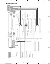
...system control terminal of ignition switch position. Subwoofer Subwoofer 8 D 67 8 A B C Orange/white To lighting switch terminal. CONNECTION DIAGRAM Downloaded from www.Manualslib.com 5manuals search engine 6 6 Multi-CD player (sold separately) This Product Rear output 15 cm Front output... Rear Speaker Rear Speaker White Gray White/black Green Gray/black Violet Green/black Violet/black Front speaker Right Rear Speaker Rear Speaker DEH-P440/XN/UC 7 7 Perform these connections when using a different amp (sold separately) IP-BUS cable Antenna jack IP-BUS input...
...system control terminal of ignition switch position. Subwoofer Subwoofer 8 D 67 8 A B C Orange/white To lighting switch terminal. CONNECTION DIAGRAM Downloaded from www.Manualslib.com 5manuals search engine 6 6 Multi-CD player (sold separately) This Product Rear output 15 cm Front output... Rear Speaker Rear Speaker White Gray White/black Green Gray/black Violet Green/black Violet/black Front speaker Right Rear Speaker Rear Speaker DEH-P440/XN/UC 7 7 Perform these connections when using a different amp (sold separately) IP-BUS cable Antenna jack IP-BUS input...


