Owner's Manual
Page 2
Before You Start About this unit 6 About this manual 6 After-sales service for buying this Pioneer product. Section 00 Contents Thank you for Pioneer products 6 Precautions 7 Use and care of a CD 18 Pausing CD playback 18 Using disc title functions 18 • Entering disc titles 18 • Displaying disc ... Introduction of advanced built-in CD player operation 17 Repeating play 17 Playing tracks in a random order 17 Scanning tracks of the remote control 7 • Installing the battery 7 • Using the remote control 7 About the XM READY mark 8 Protecting your model properly.
Before You Start About this unit 6 About this manual 6 After-sales service for buying this Pioneer product. Section 00 Contents Thank you for Pioneer products 6 Precautions 7 Use and care of a CD 18 Pausing CD playback 18 Using disc title functions 18 • Entering disc titles 18 • Displaying disc ... Introduction of advanced built-in CD player operation 17 Repeating play 17 Playing tracks in a random order 17 Scanning tracks of the remote control 7 • Installing the battery 7 • Using the remote control 7 About the XM READY mark 8 Protecting your model properly.
Owner's Manual
Page 7
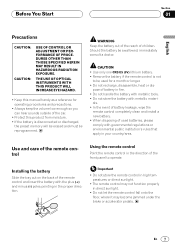
... become jammed under the brake or accelerator pedals. als. • In the event of battery leakage, wipe the remote control completely clean and install a new battery. • When disposing of used for operating procedures and precautions. • Always keep the volume low enough so you can... hear sounds outside of the front panel to be reprogrammed. Installing the battery Slide the tray out on the back of the remote control and insert the battery with governmental regulations or environmental public institution's...
... become jammed under the brake or accelerator pedals. als. • In the event of battery leakage, wipe the remote control completely clean and install a new battery. • When disposing of used for operating procedures and precautions. • Always keep the volume low enough so you can... hear sounds outside of the front panel to be reprogrammed. Installing the battery Slide the tray out on the back of the remote control and insert the battery with governmental regulations or environmental public institution's...

Other Manual
Page 1
... the input side of the same colors correctly. • If this lead separately from the vehicle for details on the cellular telephone. INSTALLATION MANUAL OF OF DEH-P640 This product conforms to an external power amp's system remote control or the car's Auto-antenna relay control terminal (max. 300 mA 12... V DC). Connect the connectors of the IP-BUS connector is blue, and the output side is installed in places that does not...
... the input side of the same colors correctly. • If this lead separately from the vehicle for details on the cellular telephone. INSTALLATION MANUAL OF OF DEH-P640 This product conforms to an external power amp's system remote control or the car's Auto-antenna relay control terminal (max. 300 mA 12... V DC). Connect the connectors of the IP-BUS connector is blue, and the output side is installed in places that does not...
Other Manual
Page 2
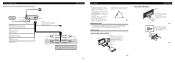
...if it .) Fig. 6 Insert the supplied extraction keys into the hole in the bottom of any connections. For details, refer to ensure proper installation. Red To electric terminal controlled by ignition switch (12 V DC) ON/OFF. Black (ground) To vehicle (metal) body. The subwoofer ... work properly. • Use only the parts included with a groove downwards and attach it overheats, so don't install the unit anywhere hot - Installation Note: • Before finally installing the unit, connect the wiring temporarily, making sure it is a sudden stop, like an emergency stop. •...
...if it .) Fig. 6 Insert the supplied extraction keys into the hole in the bottom of any connections. For details, refer to ensure proper installation. Red To electric terminal controlled by ignition switch (12 V DC) ON/OFF. Black (ground) To vehicle (metal) body. The subwoofer ... work properly. • Use only the parts included with a groove downwards and attach it overheats, so don't install the unit anywhere hot - Installation Note: • Before finally installing the unit, connect the wiring temporarily, making sure it is a sudden stop, like an emergency stop. •...

Other Manual
Page 3
... aligned (are fitted), and tighten the screws at 2 places on the shape of the frame and pull out to the unit. (Fig. 12) Fig. 11 3. Installation DIN Rear-mount Installation using fixing screws. (Fig. 13) Fixing screw Fig. 12 Fig. 13
... aligned (are fitted), and tighten the screws at 2 places on the shape of the frame and pull out to the unit. (Fig. 12) Fig. 11 3. Installation DIN Rear-mount Installation using fixing screws. (Fig. 13) Fixing screw Fig. 12 Fig. 13


