
Operating Instructions
Page 1
Video Card Carte vidéo PDA-5003 PDA-5004 Operating Instructions Mode d'emploi K042_Ja
Video Card Carte vidéo PDA-5003 PDA-5004 Operating Instructions Mode d'emploi K042_Ja

Operating Instructions
Page 2
...3_En This product complies with Video Card Model Number: PDP-504CMX/PDP-434CMX (Plasma Display) PDA-5003/PDA-5004 (Video Card) Product Category: Class B Personal Computers & Peripherals Responsible Party Name: PIONEER ELECTRONICS (USA) INC. model] IMPORTANT NOTICE - Reorient or relocate the receiving antenna. - ... than 10 cm). THIS IS FOR YOUR SECURITY. This equipment generates, uses, and can be sure to consult your Pioneer dealer first. REFER SERVICING TO QUALIFIED SERVICE PERSONNEL. D3-4-2-1-9b_En [For U.S. Operation is connected. - PLEASE WRITE THIS SERIAL...
...3_En This product complies with Video Card Model Number: PDP-504CMX/PDP-434CMX (Plasma Display) PDA-5003/PDA-5004 (Video Card) Product Category: Class B Personal Computers & Peripherals Responsible Party Name: PIONEER ELECTRONICS (USA) INC. model] IMPORTANT NOTICE - Reorient or relocate the receiving antenna. - ... than 10 cm). THIS IS FOR YOUR SECURITY. This equipment generates, uses, and can be sure to consult your Pioneer dealer first. REFER SERVICING TO QUALIFIED SERVICE PERSONNEL. D3-4-2-1-9b_En [For U.S. Operation is connected. - PLEASE WRITE THIS SERIAL...

Operating Instructions
Page 4
The PDA-5003/PDA-5004 is a video card designed for purchasing this unit, please ... 2. Before using this PIONEER product. The PDP-504CMX/PDP-50MXE1/PDP-50MXE1-S (or PDP-434CMX/PDP-43MXE1/PDP-43MXE1-S) plasma display has been originally designed as a computer monitor, but by installing the optional PDA-5003/PDA-5004 video card, the following...Connection panel 4 Installation and Connections 6 Installing the video card 6 Input connectors on the plasma display with the Pioneer Plasma Display PDP-504CMX/PDP50MXE1/PDP-50MXE1-S (or PDP-434CMX/PDP-43MXE1/PDP43MXE1-S). You will know how to...
The PDA-5003/PDA-5004 is a video card designed for purchasing this unit, please ... 2. Before using this PIONEER product. The PDP-504CMX/PDP-50MXE1/PDP-50MXE1-S (or PDP-434CMX/PDP-43MXE1/PDP-43MXE1-S) plasma display has been originally designed as a computer monitor, but by installing the optional PDA-5003/PDA-5004 video card, the following...Connection panel 4 Installation and Connections 6 Installing the video card 6 Input connectors on the plasma display with the Pioneer Plasma Display PDP-504CMX/PDP50MXE1/PDP-50MXE1-S (or PDP-434CMX/PDP-43MXE1/PDP43MXE1-S). You will know how to...

Operating Instructions
Page 5
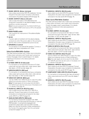
... this manual This manual has been written to allow easy understanding of setup and operating procedures when the video card PDA-5003/PDA-5004 is dedicated to the basic operations associated with selecting a source component up the video card, consult the section "... Before Proceeding Checking supplied accessories Check that the following accessories were supplied. 1 Label for remote control unit PDA-5003 RGB (BNC) PDA-5004 COMPONENT 2 Connector indicator label PDA-5003 INPUT3 INPUT4 AUDIO INPUT5 S-VIDEO VIDEO IN OUT INPUT3/4 R L (ON SYNC) G ANALOG RGB (H/V SYNC) B...
... this manual This manual has been written to allow easy understanding of setup and operating procedures when the video card PDA-5003/PDA-5004 is dedicated to the basic operations associated with selecting a source component up the video card, consult the section "... Before Proceeding Checking supplied accessories Check that the following accessories were supplied. 1 Label for remote control unit PDA-5003 RGB (BNC) PDA-5004 COMPONENT 2 Connector indicator label PDA-5003 INPUT3 INPUT4 AUDIO INPUT5 S-VIDEO VIDEO IN OUT INPUT3/4 R L (ON SYNC) G ANALOG RGB (H/V SYNC) B...

Operating Instructions
Page 7
... jack) Use to the various jacks and connectors. 1 SPEAKER (R) terminal For connection of copyguard-protected video signals (page 13). L = ...(INPUT2) (DVI-D jack) Use to an external monitor or other component. These connectors are provided (total ... connector without first consulting your Pioneer installation technician. ANALOG RGB INPUT5 AUDIO IN OUT R L G(ON SYNC) B R HD (H/V SYNC) VD R L ~ !@ # When installing PDA-5004 S-VIDEO INPUT3 AUDIO VIDEO INPUT4.../PDP-50MXE1-S model. When installing PDA-5003 S-VIDEO INPUT3 VIDEO INPUT4 INPUT 3/4 AUDIO 0 ...
... jack) Use to the various jacks and connectors. 1 SPEAKER (R) terminal For connection of copyguard-protected video signals (page 13). L = ...(INPUT2) (DVI-D jack) Use to an external monitor or other component. These connectors are provided (total ... connector without first consulting your Pioneer installation technician. ANALOG RGB INPUT5 AUDIO IN OUT R L G(ON SYNC) B R HD (H/V SYNC) VD R L ~ !@ # When installing PDA-5004 S-VIDEO INPUT3 AUDIO VIDEO INPUT4.../PDP-50MXE1-S model. When installing PDA-5003 S-VIDEO INPUT3 VIDEO INPUT4 INPUT 3/4 AUDIO 0 ...
Operating Instructions
Page 8
... VIDEO IN (INPUT4) (RCA Pin jack) For connection of components that the connection made corresponds to an external monitor or other end to a standard AC power source. = SPEAKER (L) terminal For connection of the selected source component connected to the plasma display to 10). Connect this connector, and the...of the plasma display on and off or in standby mode (page 13). # AUDIO R/L (INPUT3/4) (RCA Pin jacks) Use to an external monitor or other component. Part Names and Functions % AUDIO R/L (INPUT5) (RCA Pin jacks) Use to obtain sound when INPUT2 is provided with component ...
... VIDEO IN (INPUT4) (RCA Pin jack) For connection of components that the connection made corresponds to an external monitor or other end to a standard AC power source. = SPEAKER (L) terminal For connection of the selected source component connected to the plasma display to 10). Connect this connector, and the...of the plasma display on and off or in standby mode (page 13). # AUDIO R/L (INPUT3/4) (RCA Pin jacks) Use to an external monitor or other component. Part Names and Functions % AUDIO R/L (INPUT5) (RCA Pin jacks) Use to obtain sound when INPUT2 is provided with component ...

Operating Instructions
Page 9
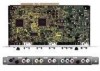
...appropriate technical knowledge and ability. Installation Illustration depicts PDA-5003 model. 1 Remove the protective cover over the video card slot on the Pioneer Plasma Display PDP-504CMX/PDP-50MXE1/PDP-50MXE1... AUDIO INPUT5 INPUT3/4 R L (ON SYNC) G ANALOG RGB (H/V SYNC) B R HD VD AUDIO R L PDA-5003 PDA-5004 RGB (BNC) COMPONENT Note Use a soft cloth to gently wipe away any way. ÷ Before installation, take...247; This video card has been designed for installation on the plasma display's terminal panel. Never rest the display on a surface in any dust or soiling from...
...appropriate technical knowledge and ability. Installation Illustration depicts PDA-5003 model. 1 Remove the protective cover over the video card slot on the Pioneer Plasma Display PDP-504CMX/PDP-50MXE1/PDP-50MXE1... AUDIO INPUT5 INPUT3/4 R L (ON SYNC) G ANALOG RGB (H/V SYNC) B R HD VD AUDIO R L PDA-5003 PDA-5004 RGB (BNC) COMPONENT Note Use a soft cloth to gently wipe away any way. ÷ Before installation, take...247; This video card has been designed for installation on the plasma display's terminal panel. Never rest the display on a surface in any dust or soiling from...

Operating Instructions
Page 10
... signals, setup using the on-screen menu is necessary after connection. I When using PDA-5003 Input connectors on the plasma display with video card Consult the following chart when making ... is compatible with Microsoft's Plug & Play (VESA DDC 1/2B). *3 Depending on the video output board of the computer, this type of connection may not be possible. *4 INPUT2 is necessary to match ... are made in order match the characteristics of the connected component. I When using PDA-5004 Input connectors on the plasma display with video card Consult the following chart when making...
... signals, setup using the on-screen menu is necessary after connection. I When using PDA-5003 Input connectors on the plasma display with video card Consult the following chart when making ... is compatible with Microsoft's Plug & Play (VESA DDC 1/2B). *3 Depending on the video output board of the computer, this type of connection may not be possible. *4 INPUT2 is necessary to match ... are made in order match the characteristics of the connected component. I When using PDA-5004 Input connectors on the plasma display with video card Consult the following chart when making...

Operating Instructions
Page 11
...OUT D-Sub INPUT1 AUDIO IN Installation and Connections On-screen setup is necessary after connection. Connection to INPUT1 or INPUT5 I When using PDA-5003 Connection to AV components Connection to the plasma display's Operating Instructions. Note When making connections to INPUT1, please refer to AV component ...use commercially available BNC/pin-plug conversion adapters to support component video signals with component video jacks. I When using PDA-5004 Connection to AV components Connection to 20. Please see pages 18 to 20. 8 En On-screen setup is necessary after connection.
...OUT D-Sub INPUT1 AUDIO IN Installation and Connections On-screen setup is necessary after connection. Connection to INPUT1 or INPUT5 I When using PDA-5003 Connection to AV components Connection to the plasma display's Operating Instructions. Note When making connections to INPUT1, please refer to AV component ...use commercially available BNC/pin-plug conversion adapters to support component video signals with component video jacks. I When using PDA-5004 Connection to AV components Connection to 20. Please see pages 18 to 20. 8 En On-screen setup is necessary after connection.

Operating Instructions
Page 12
...support component video signals with output that has the synchronization signal layered on video components. When connecting to COMPONENT VIDEO (INPUT5) [Connections for PDA-5003] ANALOG RGB INPUT5 G(ON SYNC) B R HD (H/V SYNC) VD English Installation and Connections Connect the Y signal to the Y jack,...VIDEO (INPUT5) COMPONENT VIDEO INPUT5 Y Pb/Cb Pr/Cr Installation and Connections When connecting to ANALOG RGB (INPUT5) [Connections for PDA-5004] COMPONENT VIDEO INPUT5 Y Pb/Cb Pr/Cr On-screen setup is necessary after connection. Note The plasma display and this Video Card...
...support component video signals with output that has the synchronization signal layered on video components. When connecting to COMPONENT VIDEO (INPUT5) [Connections for PDA-5003] ANALOG RGB INPUT5 G(ON SYNC) B R HD (H/V SYNC) VD English Installation and Connections Connect the Y signal to the Y jack,...VIDEO (INPUT5) COMPONENT VIDEO INPUT5 Y Pb/Cb Pr/Cr Installation and Connections When connecting to ANALOG RGB (INPUT5) [Connections for PDA-5004] COMPONENT VIDEO INPUT5 Y Pb/Cb Pr/Cr On-screen setup is necessary after connection. Note The plasma display and this Video Card...

Operating Instructions
Page 13
When connecting to ANALOG RGB (INPUT5) [Connections for PDA-5003] ANALOG RGB INPUT5 G(ON SYNC) B R HD (H/V SYNC) VD Installation and Connections When using INPUT5, set the impedance selector switch to 75 Ω (page 6). When the ... the video card and set the impedance selector switch to match the output impedance of separate SYNC analog RGB source Make separate SYNC connections for PDA-5003] ANALOG RGB INPUT5 G(ON SYNC) B R HD (H/V SYNC) VD Connection to ANALOG RGB (INPUT5) [Connections for a personal computer that the personal computer's power and display's main...
When connecting to ANALOG RGB (INPUT5) [Connections for PDA-5003] ANALOG RGB INPUT5 G(ON SYNC) B R HD (H/V SYNC) VD Installation and Connections When using INPUT5, set the impedance selector switch to 75 Ω (page 6). When the ... the video card and set the impedance selector switch to match the output impedance of separate SYNC analog RGB source Make separate SYNC connections for PDA-5003] ANALOG RGB INPUT5 G(ON SYNC) B R HD (H/V SYNC) VD Connection to ANALOG RGB (INPUT5) [Connections for a personal computer that the personal computer's power and display's main...

Operating Instructions
Page 14
...necessary after connection. Note When making G ON SYNC connections, do not make any connections to an external monitor or other component from the ANALOG RGB OUT (INPUT1) terminal when the main power of your PC's instruction manual or consult the maker or nearest dealer of this unit...the VD or HD jacks. Secure by tightening the terminal screws on the type of G ON SYNC analog RGB source Make G ON SYNC connections for PDA-5003] ANALOG RGB INPUT5 G(ON SYNC) B R HD (H/V SYNC) VD Installation and Connections To an external monitor With the plasma display, it is necessary after ...
...necessary after connection. Note When making G ON SYNC connections, do not make any connections to an external monitor or other component from the ANALOG RGB OUT (INPUT1) terminal when the main power of your PC's instruction manual or consult the maker or nearest dealer of this unit...the VD or HD jacks. Secure by tightening the terminal screws on the type of G ON SYNC analog RGB source Make G ON SYNC connections for PDA-5003] ANALOG RGB INPUT5 G(ON SYNC) B R HD (H/V SYNC) VD Installation and Connections To an external monitor With the plasma display, it is necessary after ...

Operating Instructions
Page 15
...making composite SYNC connections, do not connect anything to 20. Installation and Connections When connecting to COMPONENT VIDEO (INPUT5) [Connections for PDA-5004] COMPONENT VIDEO INPUT5 Y Pb/Cb Pr/Cr When connecting to ANALOG RGB (INPUT5) [Connections for a personal computer with both G... with output that has the vertical synchronization signal layered on top of composite SYNC analog RGB source Make composite SYNC connections for PDA-5003] ANALOG RGB INPUT5 G(ON SYNC) B R HD (H/V SYNC) VD English Installation and Connections On-screen setup is necessary ...
...making composite SYNC connections, do not connect anything to 20. Installation and Connections When connecting to COMPONENT VIDEO (INPUT5) [Connections for PDA-5004] COMPONENT VIDEO INPUT5 Y Pb/Cb Pr/Cr When connecting to ANALOG RGB (INPUT5) [Connections for a personal computer with both G... with output that has the vertical synchronization signal layered on top of composite SYNC analog RGB source Make composite SYNC connections for PDA-5003] ANALOG RGB INPUT5 G(ON SYNC) B R HD (H/V SYNC) VD English Installation and Connections On-screen setup is necessary ...

Operating Instructions
Page 16
...Personal computer On-screen setup is off or in standby mode. [When using PDA-5003] VIDEO INPUT4 IN OUT To a monitor or a recording device [When using PDA-5004] VIDEO INPUT4 IN OUT AV component To a monitor or a recording device Installation and Connections AV component AV component Signals to the ...Plug & Play (VESA DDC 2B). ¶ For the screen sizes and input signals that INPUT2 is compatible with, please refer to a separate monitor, recording device or other component with the following TV systems: NTSC, PAL, SECAM, 4.43NTSC, PAL M and PAL N. protected video signals. The...
...Personal computer On-screen setup is off or in standby mode. [When using PDA-5003] VIDEO INPUT4 IN OUT To a monitor or a recording device [When using PDA-5004] VIDEO INPUT4 IN OUT AV component To a monitor or a recording device Installation and Connections AV component AV component Signals to the ...Plug & Play (VESA DDC 2B). ¶ For the screen sizes and input signals that INPUT2 is compatible with, please refer to a separate monitor, recording device or other component with the following TV systems: NTSC, PAL, SECAM, 4.43NTSC, PAL M and PAL N. protected video signals. The...

Operating Instructions
Page 18
...the plasma display's AUDIO (INPUT2) jack (L/R). Sound is off. Sound is output from the • SPEAKER (L/R) terminals • Stereo mini jack (L/R). *1 When using the PDA-5003, the INPUT3 and INPUT4 audio input connectors are shared. When the video card is output from both the AUDIO (OUTPUT...) stereo mini jack (L/R) and the SPEAKER (L/R) terminals according to the video input selection. Video input INPUT1 ...
...the plasma display's AUDIO (INPUT2) jack (L/R). Sound is off. Sound is output from the • SPEAKER (L/R) terminals • Stereo mini jack (L/R). *1 When using the PDA-5003, the INPUT3 and INPUT4 audio input connectors are shared. When the video card is output from both the AUDIO (OUTPUT...) stereo mini jack (L/R) and the SPEAKER (L/R) terminals according to the video input selection. Video input INPUT1 ...

Operating Instructions
Page 19
English Installation and Connections [When using PDA-5003] Audio connection for component connected to INPUT3 or INPUT4 INPUT 3/4 AUDIO R L [When using PDA-5004] Audio connection for component connected to INPUT3 INPUT3 AUDIO R L Audio input to the AUDIO R/L (INPUT3/4) pin jacks is possible for a component connected ... connected to either INPUT3 or INPUT4. Sound is output from both the AUDIO (OUTPUT) stereo mini jack (L/R) and the SPEAKER (L/R) terminals according to the video input selection. Sound is output from both the AUDIO (OUTPUT) stereo mini jack (L/R) and the SPEAKER...
English Installation and Connections [When using PDA-5003] Audio connection for component connected to INPUT3 or INPUT4 INPUT 3/4 AUDIO R L [When using PDA-5004] Audio connection for component connected to INPUT3 INPUT3 AUDIO R L Audio input to the AUDIO R/L (INPUT3/4) pin jacks is possible for a component connected ... connected to either INPUT3 or INPUT4. Sound is output from both the AUDIO (OUTPUT) stereo mini jack (L/R) and the SPEAKER (L/R) terminals according to the video input selection. Sound is output from both the AUDIO (OUTPUT) stereo mini jack (L/R) and the SPEAKER...

Operating Instructions
Page 20
... Cables can be placed on the ends of 1 to fix the clamp. The illustration depicts the PDP-504CMX/PDP-50MXE1/ PDP-50MXE1-S with video card PDA-5003. * As viewed from the rear of the display. Installation and Connections To remove speed clamps Using pliers, twist the clamp 90° and pull it... the rear of the display. 12 1 Organize cables together using the 6 holes marked with the provided bead bands. Once components are included with video card PDA-5003. The illustration depicts the PDP-504CMX/PDP-50MXE1/ PDP-50MXE1-S with the plasma display for bunching cables together.
... Cables can be placed on the ends of 1 to fix the clamp. The illustration depicts the PDP-504CMX/PDP-50MXE1/ PDP-50MXE1-S with video card PDA-5003. * As viewed from the rear of the display. Installation and Connections To remove speed clamps Using pliers, twist the clamp 90° and pull it... the rear of the display. 12 1 Organize cables together using the 6 holes marked with the provided bead bands. Once components are included with video card PDA-5003. The illustration depicts the PDP-504CMX/PDP-50MXE1/ PDP-50MXE1-S with the plasma display for bunching cables together.
Operating Instructions
Page 23
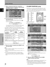
...). E N H A N C E : SETUP 0 0 0 0 0 0 0 INPUT1 OPTION PICTURE RESET 2 Use the 2/3 buttons to select [CLAMP POSITION]. Set [SIGNAL FORMAT] and [COLOR DECODING] as follows each applicable input (PDA-5003: INPUT1 or INPUT5, PDA-5004: INPUT1). ÷ When using . Incorrect settings can adversely affect the plasma display. MENU INPUT1 PICTURE SCREEN SETUP OPTION POWER MANAGEMENT CLAMP POSITION SIGNAL FORMAT...
...). E N H A N C E : SETUP 0 0 0 0 0 0 0 INPUT1 OPTION PICTURE RESET 2 Use the 2/3 buttons to select [CLAMP POSITION]. Set [SIGNAL FORMAT] and [COLOR DECODING] as follows each applicable input (PDA-5003: INPUT1 or INPUT5, PDA-5004: INPUT1). ÷ When using . Incorrect settings can adversely affect the plasma display. MENU INPUT1 PICTURE SCREEN SETUP OPTION POWER MANAGEMENT CLAMP POSITION SIGNAL FORMAT...
Operating Instructions
Page 29
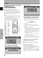
... OPTION PICTURE RESET 2 Use the 2/3 buttons to select [SETUP]. [When computer signal is input to INPUT1 or INPUT5 (PDA-5003 only), or when INPUT2 is finished, press the MENU button to INPUT 1 or INPUT 5 (PDA-5003 only), or when INPUT2 is first displayed for each input (INPUT1 to normal operation from the [AUTO POWER...
... OPTION PICTURE RESET 2 Use the 2/3 buttons to select [SETUP]. [When computer signal is input to INPUT1 or INPUT5 (PDA-5003 only), or when INPUT2 is finished, press the MENU button to INPUT 1 or INPUT 5 (PDA-5003 only), or when INPUT2 is first displayed for each input (INPUT1 to normal operation from the [AUTO POWER...

Operating Instructions
Page 45
... 1 Connector indicator label 1 Screws 2 Operating Instructions 1 Warranty 1 ÷ Due to improvements, specifications and design are subject to 104 °F) I PDA-5004 Input/output Video INPUT3 Input S jack (Mini DIN 4 pin) • Y/C separate video signal INPUT4 Y . . . 1 Vp-p/75 Ω/...Pin jack (x2) L/R ... 500mVrms/more than 10 kΩ Accessories Label for INPUT5) Pin jack (x2) L/R ... 500mVrms/more than 10 kΩ I PDA-5003 Input/output Video INPUT3 Input INPUT4 S jack (Mini DIN 4 pin) • Y/C separate video signal Y . . . 1 Vp-p/75 Ω/negative ...
... 1 Connector indicator label 1 Screws 2 Operating Instructions 1 Warranty 1 ÷ Due to improvements, specifications and design are subject to 104 °F) I PDA-5004 Input/output Video INPUT3 Input S jack (Mini DIN 4 pin) • Y/C separate video signal INPUT4 Y . . . 1 Vp-p/75 Ω/...Pin jack (x2) L/R ... 500mVrms/more than 10 kΩ Accessories Label for INPUT5) Pin jack (x2) L/R ... 500mVrms/more than 10 kΩ I PDA-5003 Input/output Video INPUT3 Input INPUT4 S jack (Mini DIN 4 pin) • Y/C separate video signal Y . . . 1 Vp-p/75 Ω/negative ...
