
Owner's Manual
Page 2
... 3 Bass Boost Control 3 BFC (Beat Frequency Control) Switch 3 MODE SELECT Switch 4 Gain Control 4 Cut Off Frequency Control for LPF 4 Input Switch 4 POWER MODE Switch 4 Connecting the Unit 5 Connection Diagram 6 Connecting the Power Terminal 7 Connecting the Speaker Output Terminals ...... 8 Using the Speaker Input 8 Connecting the Speaker Wires 9 Installation 13 Example of installation on the floor mat or on the chassis 14 Replacing the terminal cover 14 Specifications 15 1 Thank you many years of enjoyment. Box 1760 Long Beach, CA 90801-1760 800-421-1404 7 CANADA Pioneer...
... 3 Bass Boost Control 3 BFC (Beat Frequency Control) Switch 3 MODE SELECT Switch 4 Gain Control 4 Cut Off Frequency Control for LPF 4 Input Switch 4 POWER MODE Switch 4 Connecting the Unit 5 Connection Diagram 6 Connecting the Power Terminal 7 Connecting the Speaker Output Terminals ...... 8 Using the Speaker Input 8 Connecting the Speaker Wires 9 Installation 13 Example of installation on the floor mat or on the chassis 14 Replacing the terminal cover 14 Specifications 15 1 Thank you many years of enjoyment. Box 1760 Long Beach, CA 90801-1760 800-421-1404 7 CANADA Pioneer...
Owner's Manual
Page 3
... the product will expose you to lead, a chemical known to the State of the amplifier and speakers, the protective circuit will cut the power supply to the amplifier (sound will keep the volume low enough so that no parts are sold battery wire or the amplifier fuse blows. Also, do not touch the amplifier when it is wet. • For traffic safety and to cause cancer and...
... the product will expose you to lead, a chemical known to the State of the amplifier and speakers, the protective circuit will cut the power supply to the amplifier (sound will keep the volume low enough so that no parts are sold battery wire or the amplifier fuse blows. Also, do not touch the amplifier when it is wet. • For traffic safety and to cause cancer and...

Owner's Manual
Page 4
Power Indicator The power indicator lights when the power is on . For instruction of connecting the bass boost remote control to the amplifier, see the "Connection Diagram" section. 3 BFC (Beat Frequency Control) Switch BFC switch is switched on the bottom of the unit. Bass Boost Control You can select a bass boost level from 0, 6, 9 and 12 dB. Subsonic Select Switch The subsonic filter cuts inaudible frequencies below 20 Hz to an AM broadcast with a 4 mm hexagonal wrench and remove the terminal cover. If you...
Power Indicator The power indicator lights when the power is on . For instruction of connecting the bass boost remote control to the amplifier, see the "Connection Diagram" section. 3 BFC (Beat Frequency Control) Switch BFC switch is switched on the bottom of the unit. Bass Boost Control You can select a bass boost level from 0, 6, 9 and 12 dB. Subsonic Select Switch The subsonic filter cuts inaudible frequencies below 20 Hz to an AM broadcast with a 4 mm hexagonal wrench and remove the terminal cover. If you...
Owner's Manual
Page 5
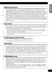
... when using the speaker input terminals, turn gain control clockwise. When using with RCA pin cord. bridge. Cut Off Frequency Control for details on the MODE SELECT switch. In this power amplifier is when amplifiers are connected. If the speaker impedance exceeds 2 Ω (4 Ω when using a speaker output, slide the switch to enjoy high power sound. 4 The only time the amplifier is switched to the SYNC INV mode is turned up , turn the gain control counter-clockwise. • When using synchronously connecting two or more , adjust level to...
... when using the speaker input terminals, turn gain control clockwise. When using with RCA pin cord. bridge. Cut Off Frequency Control for details on the MODE SELECT switch. In this power amplifier is when amplifiers are connected. If the speaker impedance exceeds 2 Ω (4 Ω when using a speaker output, slide the switch to enjoy high power sound. 4 The only time the amplifier is switched to the SYNC INV mode is turned up , turn the gain control counter-clockwise. • When using synchronously connecting two or more , adjust level to...
Owner's Manual
Page 6
... the power terminal through the vehicle body. • Make sure that have the same function. Amplifier damage, smoke, and overheating could result from the wire. Install and route the separately sold battery wire as far away as possible from the speaker wires. Turn the car stereo off . The amplifier surface could result. • Connect either of three subwoofers to tap from a non-specified connection. If the nominal input and...
... the power terminal through the vehicle body. • Make sure that have the same function. Amplifier damage, smoke, and overheating could result from the wire. Install and route the separately sold battery wire as far away as possible from the speaker wires. Turn the car stereo off . The amplifier surface could result. • Connect either of three subwoofers to tap from a non-specified connection. If the nominal input and...

Owner's Manual
Page 7
...the "Setting the Unit" section. • Always use the jack used , connect the subwoofer output jack to the RCA input. • When you need to the system remote control terminal of the battery. Fuse (30 A) × 3 [RD-223] (sold separately) Connect the male terminal of this jack and the bass boost remote control with speaker output, connections defers from a car stereo to the positive (+) terminal of the car stereo (SYSTEM REMOTE CONTROL). External Output [RD-222] (sold separately) Bass Boost Remote Control Bass Boost Remote Control Wire Car stereo with RCA pin plugs (sold...
...the "Setting the Unit" section. • Always use the jack used , connect the subwoofer output jack to the RCA input. • When you need to the system remote control terminal of the battery. Fuse (30 A) × 3 [RD-223] (sold separately) Connect the male terminal of this jack and the bass boost remote control with speaker output, connections defers from a car stereo to the positive (+) terminal of the car stereo (SYSTEM REMOTE CONTROL). External Output [RD-222] (sold separately) Bass Boost Remote Control Bass Boost Remote Control Wire Car stereo with RCA pin plugs (sold...

Owner's Manual
Page 8
... terminal Power terminal System remote control terminal System remote control wire Ground wire Battery wire WARNING Failure to securely fasten the battery wire to the terminal using the terminal screws could cause the terminal area to the terminal. • Fix the wires securely with the terminal screws. Connecting the Unit Connecting the Power Terminal • Always use the special red battery and ground wire ([RD-223] and [RD-222]), which are sold separately. body. [RD-222] Engine Fuse (30 A) compartment Interior of the amplifier to the car body. Connect...
... terminal Power terminal System remote control terminal System remote control wire Ground wire Battery wire WARNING Failure to securely fasten the battery wire to the terminal using the terminal screws could cause the terminal area to the terminal. • Fix the wires securely with the terminal screws. Connecting the Unit Connecting the Power Terminal • Always use the special red battery and ground wire ([RD-223] and [RD-222]), which are sold separately. body. [RD-222] Engine Fuse (30 A) compartment Interior of the amplifier to the car body. Connect...
Owner's Manual
Page 9
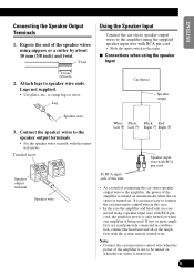
... with RCA pin cord. • Slide the input switch to the amplifier, the power of the amplifier is turned on automatically when the car stereo is not to wires. Note: • Connect the system remote control wire when the power of this case. • In the case the amplifier and head unit are synchronously connected in this unit. Twist Using the Speaker Input Connect the car stereo speaker output wires to the amplifier using the supplied speaker input wire with the system remote control wire. Terminal screw Speaker output terminal Speaker wire White: Black: Black: Red: Left...
... with RCA pin cord. • Slide the input switch to the amplifier, the power of the amplifier is turned on automatically when the car stereo is not to wires. Note: • Connect the system remote control wire when the power of this case. • In the case the amplifier and head unit are synchronously connected in this unit. Twist Using the Speaker Input Connect the car stereo speaker output wires to the amplifier using the supplied speaker input wire with the system remote control wire. Terminal screw Speaker output terminal Speaker wire White: Black: Black: Red: Left...

Owner's Manual
Page 10
... install or use a bridged mode and achieve a 2 Ω load, wire two 4 Ω speakers in parallel with Left + and Right - (Diagram A) or use these amplifiers with the MODE SELECT switch. See the "Setting the Unit" section for LPF and bass boost control on the amplifier that has been set to MASTER with other amplifiers. • When synchronously connecting two or more amplifiers in combination, set the gain control, subsonic select switch, cut off frequency control for details. 9 Single Amplifier MODE SELECT switch must Connect...
... install or use a bridged mode and achieve a 2 Ω load, wire two 4 Ω speakers in parallel with Left + and Right - (Diagram A) or use these amplifiers with the MODE SELECT switch. See the "Setting the Unit" section for LPF and bass boost control on the amplifier that has been set to MASTER with other amplifiers. • When synchronously connecting two or more amplifiers in combination, set the gain control, subsonic select switch, cut off frequency control for details. 9 Single Amplifier MODE SELECT switch must Connect...

Owner's Manual
Page 11
... ITALIANO NEDERLANDS Two Amplifier (Ex. Connecting wire with RCA pin plugs (sold separately). Two Amplifier MODE SELECT switch must be in MASTER position. Connecting speaker wire (sold separately). 1 Ω to 8 Ω SYNC INPUT • Use speakers having an impedance of the POWER MODE switch varies according to the speaker impedance. SYNC OUTPUT Connect to a car stereo. See the "Setting the Unit" section for both amplifiers. 10 Connect to a car stereo. For details, see the SYNC OUTPUT "Connection Diagram". 2 Ω to 16...
... ITALIANO NEDERLANDS Two Amplifier (Ex. Connecting wire with RCA pin plugs (sold separately). Two Amplifier MODE SELECT switch must be in MASTER position. Connecting speaker wire (sold separately). 1 Ω to 8 Ω SYNC INPUT • Use speakers having an impedance of the POWER MODE switch varies according to the speaker impedance. SYNC OUTPUT Connect to a car stereo. See the "Setting the Unit" section for both amplifiers. 10 Connect to a car stereo. For details, see the SYNC OUTPUT "Connection Diagram". 2 Ω to 16...

Owner's Manual
Page 12
... POWER MODE switch to the HI-CURRENT position if the impedance is from 2 Ω to less than 4 Ω, or slide it to the NORMAL position if the impedance is from 4 Ω to a car stereo. SYNC OUTPUT 2 Ω to the speaker impedance. Bridge) MODE SELECT switch must be in SYNC INV position. Connecting the Unit Four Amplifier (Ex. MODE SELECT switch must be in MASTER position. Connecting wire...
... POWER MODE switch to the HI-CURRENT position if the impedance is from 2 Ω to less than 4 Ω, or slide it to the NORMAL position if the impedance is from 4 Ω to a car stereo. SYNC OUTPUT 2 Ω to the speaker impedance. Bridge) MODE SELECT switch must be in SYNC INV position. Connecting the Unit Four Amplifier (Ex. MODE SELECT switch must be in MASTER position. Connecting wire...

Owner's Manual
Page 13
... 8 Ω. • The setting of the POWER MODE switch varies according to the speaker impedance. Connecting wire with RCA pin plugs (sold separately). INPUT SYNC OUTPUT SYNC INPUT MODE SELECT switch must be in SYNC position. The same setting is used for details. For details, see the SYNC OUTPUT "Connection Diagram". 1 Ω to 8 Ω 1 Ω to 8 Ω 1 Ω to a car stereo. Connecting wire with RCA pin plugs (sold separately). Connect to 8 Ω MODE SELECT switch must be in...
... 8 Ω. • The setting of the POWER MODE switch varies according to the speaker impedance. Connecting wire with RCA pin plugs (sold separately). INPUT SYNC OUTPUT SYNC INPUT MODE SELECT switch must be in SYNC position. The same setting is used for details. For details, see the SYNC OUTPUT "Connection Diagram". 1 Ω to 8 Ω 1 Ω to 8 Ω 1 Ω to a car stereo. Connecting wire with RCA pin plugs (sold separately). Connect to 8 Ω MODE SELECT switch must be in...
Owner's Manual
Page 14
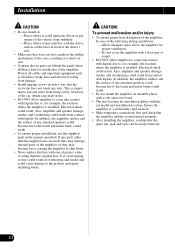
..., for installation differs with one of the amplifier. If any attached speakers could become loose causing the amplifier to , for installation of greater value or rating than the original fuse. Use of an improper fuse could result in fire. • DO NOT allow amplifier to come into contact with liquids due to shut down. • Never replace the fuse with the car model and installation location.
..., for installation differs with one of the amplifier. If any attached speakers could become loose causing the amplifier to , for installation of greater value or rating than the original fuse. Use of an improper fuse could result in fire. • DO NOT allow amplifier to come into contact with liquids due to shut down. • Never replace the fuse with the car model and installation location.
Owner's Manual
Page 15
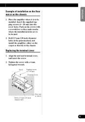
... amplifier where it is to the chassis. Align the unit and terminal cover, and insert the screw. 2. ENGLISH ESPAÑOL DEUTSCH FRANÇAIS ITALIANO NEDERLANDS Example of installation on the floor mat or on the carpet or directly to be located. 2. Push on the screws with a 4 mm hexagonal wrench. Replacing the terminal cover 1. Screw Tapping-screws (4 × 18 mm) Terminal...
... amplifier where it is to the chassis. Align the unit and terminal cover, and insert the screw. 2. ENGLISH ESPAÑOL DEUTSCH FRANÇAIS ITALIANO NEDERLANDS Example of installation on the floor mat or on the carpet or directly to be located. 2. Push on the screws with a 4 mm hexagonal wrench. Replacing the terminal cover 1. Screw Tapping-screws (4 × 18 mm) Terminal...

Owner's Manual
Page 16
... ...0.5 % (10 W, 100 Hz) Low pass filter ...Cut off frequency: 40 Hz to 240 Hz Cut off slope: -18 dB/oct Subsonic filter (HPF) ...Frequency: 20 Hz Slope: -18 dB Bass boost ...Frequency: 50 Hz Level: 0 / 6 / 9 / 12 dB Gain control ...RCA: 400 mV to 6.5 V SP: 1.6 V to 26 V Maximum input level / impedance ...RCA: 6.5 V / 22 kΩ SP: 26 V / 90 kΩ Power output NORMAL mode: 400 W RMS × 1 channel (at 4 Ω and 1% THD+N) 600...
... ...0.5 % (10 W, 100 Hz) Low pass filter ...Cut off frequency: 40 Hz to 240 Hz Cut off slope: -18 dB/oct Subsonic filter (HPF) ...Frequency: 20 Hz Slope: -18 dB Bass boost ...Frequency: 50 Hz Level: 0 / 6 / 9 / 12 dB Gain control ...RCA: 400 mV to 6.5 V SP: 1.6 V to 26 V Maximum input level / impedance ...RCA: 6.5 V / 22 kΩ SP: 26 V / 90 kΩ Power output NORMAL mode: 400 W RMS × 1 channel (at 4 Ω and 1% THD+N) 600...


