
Owner's Manual
Page 2
...Terminals ...... 8 Connecting the Power Terminal 9 Setting the Gain for synced amplifier 10 Connecting the Speaker Wires 10 Installation 15 Attaching the Bass boost remote control ........ 15 Example of installation on the floor mat or on the chassis 16 Replacing the terminal cover... 800-421-1404 7 CANADA Pioneer Electronics of this manual before attempting operation. Pioneer Electronics (USA) Inc. PIONEER SUGGESTS USING A PROFESSIONAL INSTALLER DUE TO THE COMPLEXITY OF THIS PRODUCT. Please read all instructions and WARNINGS in this amplifier is designed to User Alteration ...
...Terminals ...... 8 Connecting the Power Terminal 9 Setting the Gain for synced amplifier 10 Connecting the Speaker Wires 10 Installation 15 Attaching the Bass boost remote control ........ 15 Example of installation on the floor mat or on the chassis 16 Replacing the terminal cover... 800-421-1404 7 CANADA Pioneer Electronics of this manual before attempting operation. Pioneer Electronics (USA) Inc. PIONEER SUGGESTS USING A PROFESSIONAL INSTALLER DUE TO THE COMPLEXITY OF THIS PRODUCT. Please read all instructions and WARNINGS in this amplifier is designed to User Alteration ...

Owner's Manual
Page 3
...L (left) and R (right) channels are behind the panel when drilling a hole for installation of greater value or rating than the original fuse. CAUTION • Never replace the fuse with another one of the amplifier. Wash hands after handling. • Always use of a long, commercially available hexagonal wrench ... use the recommended battery wire and ground wire, which is installed. Connect the battery wire directly to the car battery positive terminal (+) and the ground wire to the car body. • Do not touch the amplifier with the product may expose you may get an electric shock...
...L (left) and R (right) channels are behind the panel when drilling a hole for installation of greater value or rating than the original fuse. CAUTION • Never replace the fuse with another one of the amplifier. Wash hands after handling. • Always use of a long, commercially available hexagonal wrench ... use the recommended battery wire and ground wire, which is installed. Connect the battery wire directly to the car battery positive terminal (+) and the ground wire to the car body. • Do not touch the amplifier with the product may expose you may get an electric shock...

Owner's Manual
Page 7
... at rest or idling, the battery may catch fire, emit smoke or become hot to the touch and minor burns could cause damage to the amplifier; 1: a subwoofer with a 500 W or larger nominal input and an impedance 4 Ω, 2: a subwoofer with a 1 000 W or larger nominal input and an ...8486; or 3: a subwoofer with a 12-volt battery and negative grounding. The amplifier surface could also become damaged. • Install and route the separately sold battery wire, ground wire, speaker wires and the amplifier as far away as possible from the wire. If the nominal input and impedance...
... at rest or idling, the battery may catch fire, emit smoke or become hot to the touch and minor burns could cause damage to the amplifier; 1: a subwoofer with a 500 W or larger nominal input and an impedance 4 Ω, 2: a subwoofer with a 1 000 W or larger nominal input and an ...8486; or 3: a subwoofer with a 12-volt battery and negative grounding. The amplifier surface could also become damaged. • Install and route the separately sold battery wire, ground wire, speaker wires and the amplifier as far away as possible from the wire. If the nominal input and impedance...
Owner's Manual
Page 12
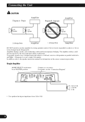
... stereo. For details, see the "Connection Diagram". • Use speakers having an impedance from improper bridging. Amplifier damage, smoke, and overheating could result. Connect to 8 Ω 1 200 W (1 Ω) 11 Connecting the Unit CAUTION Diagram A - To properly install or use a bridged mode and achieve a 2 Ω load, wire two 4 Ω speakers in MASTER position...
... stereo. For details, see the "Connection Diagram". • Use speakers having an impedance from improper bridging. Amplifier damage, smoke, and overheating could result. Connect to 8 Ω 1 200 W (1 Ω) 11 Connecting the Unit CAUTION Diagram A - To properly install or use a bridged mode and achieve a 2 Ω load, wire two 4 Ω speakers in MASTER position...

Owner's Manual
Page 16
..., such as on unstable places such as the spare tire board. • The best location for example, the location where the amplifier is installed. Electrical shock could result. Use of any attached speakers could become hot to the touch and minor burns could result. • Do ...screws (3 mm × 10 mm) at a sufficiently rigid location. • Make temporary connections first and check that the amplifier and the system operate properly. • After installing the amplifier, confirm that the spare tire, jack and tools can result in such a way that no parts are not caught in ...
..., such as on unstable places such as the spare tire board. • The best location for example, the location where the amplifier is installed. Electrical shock could result. Use of any attached speakers could become hot to the touch and minor burns could result. • Do ...screws (3 mm × 10 mm) at a sufficiently rigid location. • Make temporary connections first and check that the amplifier and the system operate properly. • After installing the amplifier, confirm that the spare tire, jack and tools can result in such a way that no parts are not caught in ...
Owner's Manual
Page 17
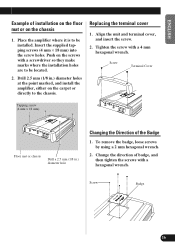
...mm (1/8 in .) diameter holes at the point marked, and install the amplifier, either on the carpet or directly to the chassis. To remove the badge, loose screws by using a 2 mm hexagonal wrench. 2. Change the direction of installation on the floor mat or on the screws with a screwdriver so...hexagonal wrench. Screw Badge 16 Insert the supplied tapping screws (4 mm × 18 mm) into the screw holes. Place the amplifier where it is to be installed. Align the unit and terminal cover, and insert the screw. 2. ENGLISH ESPAÑOL DEUTSCH FRANÇAIS ITALIANO NEDERLANDS ...
...mm (1/8 in .) diameter holes at the point marked, and install the amplifier, either on the carpet or directly to the chassis. To remove the badge, loose screws by using a 2 mm hexagonal wrench. 2. Change the direction of installation on the floor mat or on the screws with a screwdriver so...hexagonal wrench. Screw Badge 16 Insert the supplied tapping screws (4 mm × 18 mm) into the screw holes. Place the amplifier where it is to be installed. Align the unit and terminal cover, and insert the screw. 2. ENGLISH ESPAÑOL DEUTSCH FRANÇAIS ITALIANO NEDERLANDS ...

Owner's Manual
Page 18
... check the wiring (see the "WARNING" section on page 2). When this happens, immediately discontinue use of the amplifier and check the location where the amplifier is installed (see the "WARNING" section on . Contact your dealer if the problem is not a malfunction. This is still not corrected. HEAT Indicator • This indicator lights ...
... check the wiring (see the "WARNING" section on page 2). When this happens, immediately discontinue use of the amplifier and check the location where the amplifier is installed (see the "WARNING" section on . Contact your dealer if the problem is not a malfunction. This is still not corrected. HEAT Indicator • This indicator lights ...

